2007 TOYOTA SIENNA low idle
[x] Cancel search: low idlePage 58 of 3000

INTRODUCTION – TERMSIN–51
IN
IFI Indirect Fuel Injection Indirect Injection (IDL)
IFS Inertia Fuel-Shutoff -
ISC Idle Speed Control -
KS Knock Sensor Knock Sensor
MAF Mass Airflow Air Flow Meter
MAP Manifold Absolute Pressure Manifold Pressure Intake Vacuum
MC Mixture ControlElectric Bleed Air Control Valve (EBCV)
Mixture Control Valve (MCV)
Electric Air Control Valve (EACV)
MDP Manifold Differential Pressure -
MFI Multiport Fuel Injection Electronic Fuel Injection (EFI)
MIL Malfunction Indicator Light Check Engine Light
MST Manifold Surface Temperature -
MVZ Manifold Vacuum Zone -
NVRAM Non-Volatile Random Access Memory -
O2S Oxygen SensorOxygen Sensor, O
2 Sensor (O2S)
OBD On-Board Diagnostic On-Board Diagnostic System (OBD)
OC Oxidation Catalytic Converter Oxidation Catalytic Convert (OC), CCo
OL Open Loop Open Loop
PAIR Pulsed Secondary Air Injection Air Suction (AS)
PCM Powertrain Control Module -
PNP Park/Neutral Position -
PROM Programmable Read Only Memory -
PSP Power Steering Pressure -
PTOX Periodic Trap OxidizerDiesel Particulate Filter (DPF)
Diesel Particulate Trap (DPT)
RAM Random Access Memory Random Access Memory (RAM)
RM Relay Module -
ROM Read Only Memory Read Only Memory (ROM)
RPM Engine Speed Engine Speed
SC Supercharger Supercharger
SCB Supercharger Bypass E-ABV
SFI Sequential Multiport Fuel Injection Electronic Fuel Injection (EFI), Sequential Injection
SPL Smoke Puff Limiter -
SRI Service Reminder Indicator -
SRT System Readiness Test -
ST Scan Tool -
TB Throttle Body Throttle Body
TBI Throttle Body Fuel InjectionSingle Point Injection
Central Fuel Injection (Ci)
TC Turbocharger Turbocharger
TCC Torque Converter Clutch Torque Converter
TCM Transmission Control Module Transmission ECU, ECT ECU
TP Throttle Position Throttle Position
TR Transmission Range -
TVV Thermal Vacuum ValveBimetallic Vacuum Switching Valve (BVSV)
Thermostatic Vacuum Switching Valve (TVSV)
TWC Three-Way Catalytic ConverterThree-Way Catalytic (TWC)
Manifold Converter
CC
RO
SAE
ABBREVIATIONSSAE TERMSTOYOTA TERMS
( )-ABBREVIATIONS
Page 318 of 3000

2GR-FE ENGINE CONTROL SYSTEM – SFI SYSTEMES–1
ES
SFI SYSTEM
PRECAUTION
1. INITIALIZATION
NOTICE:
• Perform RESET MEMORY (AT initialization) when
replacing the automatic transaxle assembly, engine
assembly or ECM (See page AX-16).
• Perform REGISTRATION (VIN registration) when
replacing the ECM (See page ES-15).
HINT:
Initialization cannot be completed by only removing the
battery.
2. FOR USING INTELLIGENT TESTER
CAUTION:
Observe the following items for safety reasons:
• Before using the tester, read the instruction
manual.
• Prevent the tester cable from being caught on the
pedals, shift lever and steering wheel when
driving with the tester connected to the vehicle.
• When driving the vehicle for testing purposes
using the tester, two persons are required. One is
for driving the vehicle, and the other operates the
tester.
3. FOR USING BATTERY DURING INSPECTION
(a) While using the battery during inspection, do not
bring the positive and negative tester probes too
close to each other as a short circuit may occur.
4. COOLING FAN SYSTEM
NOTICE:
• When the ignition switch is turned off and the engine
temperature is high, the cooling fans may operate for
approximately 3 minutes.
• After turning the ignition switch off, keep hands and
objects away from the fans when they are operating.
HINT:
If all of the following are met for a certain period of time during
a few minute period immediately before the engine is
stopped, the electric fans will continue to operate for 3
minutes after the engine is stopped. This is performed to
ensure restartability and stabilize idle speed.
– The intelligent tester indicates a very high coolant
temperature.
– The intelligent tester indicates a high outside air
temperature.
– The vehicle has been driven under high load (driving on an
uphill or equivalent).
The following sensors are used for this control:
– Coolant temperature sensor
– Outside air temperature sensor
–MAF sensor
– Vehicle speed sensors
Page 327 of 3000

2GR-FE ENGINE CONTROL SYSTEM – SFI SYSTEMES–259
ES
TYPICAL ENABLING CONDITIONS
TYPICAL MALFUNCTION THRESHOLDS
MONITOR RESULT
Refer to CHECKING MONITOR STATUS (See page ES-19).
CONDITIONING FOR SENSOR TESTING
HINT:
Perform the operation with the engine speeds and durations described below prior to checking the
waveforms of the A/F and HO2 sensors. This is in order to activate the sensors sufficiently to obtain the
appropriate inspection results.
The monitor will run whenever these DTCs are not
presentP0011, P0012 (VVT System 1-Advance, Retard), P0021, P0022 (VVT System 2-
Adavance, Retard), P0031, P0032, P0051, P0052 (A/F Sensor Heater Sensor 1),
P0037, P0038, P0057, P0058 (O2 Sensor heater Sensor 2), P0100, P0101, P0102,
P0103 (MAF Sensor), P0115, P0116, P0117, P0118 (ECT Sensor), P0120, P0121,
P0122, P0123, P0220, P0222, P0223 , P2135 (TP Sensor), P0125 (Insufficient ECT
for Closed Loop), P0136, P0156 (O2 Sensor 2), P0171,P0172 (Fuel System),
P0300, P0301, P0302, P0303, P0304, P0305, P0306 (Misfire), P0335 (CKP
Sensor), P0340 (CMP Sensor), P0351, P0352, P0353, P0354, P0355, P0356
(Ignitor), P0500 (VSS), P2196, P2198 (A/F Sensor (Rationality)), P2A00, P2A03 (A/
F Sensor (Slow Response))
Battery voltage 11 V or more
IAT -10
C (14F) or more
ECT 75
C (167F) or more
Atmospheric pressure 0.75 or more
Idle OFF
Engine RPM Less than 3200 rpm
A/F sensor Activated
Fuel system status Closed loop
Engine load 10 to 70%
All of the following conditions are met Conditions 1, 2 and 3
1. Mass air flow rate 5 to 60 g/sec.
2. Front catalyst temperature (estimated) 600 to 750
C (1112 to 1382F)
3. Rear catalyst temperature (estimated) 100 to 900
C (212 to 1652F)
Rear HO2S monitor Completed
Shift position 4th or more
Oxygen Storage Capacity (OSC) of catalyst Less than 0.046 g (0.000101 lb)
Page 356 of 3000

ES–302GR-FE ENGINE CONTROL SYSTEM – SFI SYSTEM
ES
(3) Clear the DTCs.
(4) Start the engine.
(5) Allow the engine to idle for 10 minutes or more.
(6) Drive the vehicle at 25 mph (40 km/h) or more
for at least 2 minutes.
(c) Monitor Status
(1) Check the Readiness Monitor status displayed
on the tester or scan tool.
If the status does not switch to COMPL
(complete), make sure that the preconditions
have been met, and repeat the Drive Pattern.
Page 357 of 3000

2GR-FE ENGINE CONTROL SYSTEM – SFI SYSTEMES–31
ES
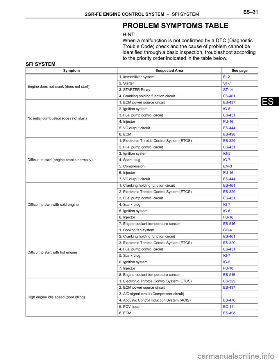
PROBLEM SYMPTOMS TABLE
HINT:
When a malfunction is not confirmed by a DTC (Diagnostic
Trouble Code) check and the cause of problem cannot be
identified through a basic inspection, troubleshoot according
to the priority order indicated in the table below.
SFI SYSTEM
Symptom Suspected Area See page
Engine does not crank (does not start)1. Immobilizer systemEI-2
2. StarterST-7
3. STARTER RelayST-14
4. Cranking holding function circuitES-461
No initial combustion (does not start)1. ECM power source circuitES-437
2. Ignition systemIG-5
3. Fuel pump control circuitES-451
4. InjectorFU-16
5. VC output circuitES-444
6. ECMES-498
Difficult to start (engine cranks normally)1. Electronic Throttle Control System (ETCS)ES-329
2. Fuel pump control circuitES-451
3. Ignition systemIG-5
4. Spark plugIG-7
5. CompressionEM-3
6. InjectorFU-16
7. VC output circuitES-444
Difficult to start with cold engine1. Cranking holding function circuitES-461
2. Electronic Throttle Control System (ETCS)ES-329
3. Fuel pump control circuitES-451
4. Spark plugIG-7
5. Ignition systemIG-6
6. InjectorFU-16
7. Engine coolant temperature sensorES-516
Difficult to start with hot engine1. Cooling fan systemCO-4
2. Cranking holding function circuitES-461
3. Electronic Throttle Control System (ETCS)ES-329
4. Fuel pump control circuitES-451
5. Spark plugIG-7
6. Ignition systemIG-5
7. InjectorFU-16
8. Engine coolant temperature sensorES-516
High engine idle speed (poor idling)1. Electronic Throttle Control System (ETCS)ES-329
2. ECM power source circuitES-437
3. A/C signal circuit (Compressor circuit) -
4. Acoustic Control Induction System (ACIS)ES-470
5. PCV hoseEC-15
6. ECMES-498
Page 358 of 3000

ES–322GR-FE ENGINE CONTROL SYSTEM – SFI SYSTEM
ES
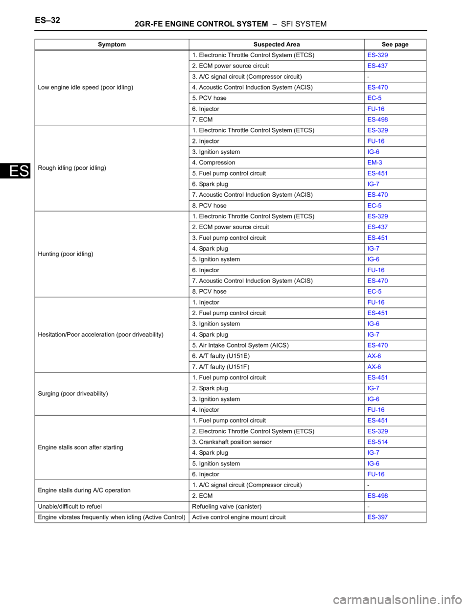
Low engine idle speed (poor idling)1. Electronic Throttle Control System (ETCS)ES-329
2. ECM power source circuitES-437
3. A/C signal circuit (Compressor circuit) -
4. Acoustic Control Induction System (ACIS)ES-470
5. PCV hoseEC-5
6. InjectorFU-16
7. ECMES-498
Rough idling (poor idling)1. Electronic Throttle Control System (ETCS)ES-329
2. InjectorFU-16
3. Ignition systemIG-6
4. CompressionEM-3
5. Fuel pump control circuitES-451
6. Spark plugIG-7
7. Acoustic Control Induction System (ACIS)ES-470
8. PCV hoseEC-5
Hunting (poor idling)1. Electronic Throttle Control System (ETCS)ES-329
2. ECM power source circuitES-437
3. Fuel pump control circuitES-451
4. Spark plugIG-7
5. Ignition systemIG-6
6. InjectorFU-16
7. Acoustic Control Induction System (ACIS)ES-470
8. PCV hoseEC-5
Hesitation/Poor acceleration (poor driveability)1. InjectorFU-16
2. Fuel pump control circuitES-451
3. Ignition systemIG-6
4. Spark plugIG-7
5. Air Intake Control System (AICS)ES-470
6. A/T faulty (U151E)AX-6
7. A/T faulty (U151F)AX-6
Surging (poor driveability)1. Fuel pump control circuitES-451
2. Spark plugIG-7
3. Ignition systemIG-6
4. InjectorFU-16
Engine stalls soon after starting1. Fuel pump control circuitES-451
2. Electronic Throttle Control System (ETCS)ES-329
3. Crankshaft position sensorES-514
4. Spark plugIG-7
5. Ignition systemIG-6
6. InjectorFU-16
Engine stalls during A/C operation1. A/C signal circuit (Compressor circuit) -
2. ECMES-498
Unable/difficult to refuel Refueling valve (canister) -
Engine vibrates frequently when idling (Active Control) Active control engine mount circuitES-397 Symptom Suspected Area See page
Page 369 of 3000

2GR-FE ENGINE CONTROL SYSTEM – SFI SYSTEMES–51
ES
FAIL-SAFE CHART
If any of the following DTCs are set, the ECM enters fail-safe
mode to allow the vehicle to be driven temporarily.
HINT:
• *1: The vehicle can be driven slowly when the accelerator
pedal is depressed firmly and slowly. If the accelerator
pedal is depressed quickly, the vehicle may speed up and
slow down erratically.
• *2: Misfire related fail-safe operations occur when catalyst
overheat malfunctions occur.
DTCs Components Fail-Safe OperationsFail-Safe Deactivation
Conditions
P0031, P0032, P0051 and P0052Air-Fuel Ratio (A/F) Sensor
HeaterECM turns off A/F sensor heater Ignition switch off
P0037, P0038, P0057 and P0058Heated Oxygen (HO2) Sensor
HeaterECM turns off HO2 sensor heater Ignition switch off
P0100, P0102 and P0103 Mass Air Flow (MAF) MeterECM calculates ignition timing
according to engine speed and
throttle valve positionPass condition detected
P0110, P0112 and P0113Intake Air Temperature (IAT)
SensorECM estimates IAT to be 20
C
(68
F)Pass condition detected
P0115, P0117 and P0118Engine Coolant Temperature
(ECT) SensorECM estimates ECT to be 80
C
(176
F)Pass condition detected
P0120, P0121, P0122, P0123,
P0220, P0222, P0223, P0604,
P0606, P0607, P0657, P2102,
P2103, P2111, P2112, P2118,
P2119 and P2135Electronic Throttle Control
System (ETCS)ECM cuts off throttle actuator
current and throttle valve returned
to 6.5
throttle position by return
spring
ECM then adjusts engine output
by controlling fuel injection
(intermittent fuel-cut) and ignition
timing in accordance with
accelerator pedal opening angle,
to allow vehicle to continue at
minimal speed*1Pass condition detected and then
ignition switch turned off
P0300, P0301, P0302, P0303,
P0304, P0305 and P0306*2• Fuel injector
• Electronic Throttle Control
System (ETCS)When misfire occurs, fuel cut is
performed for catalyst overheat
malfunction prevention
• During normal load and
normal engine speed (MIL is
blinking)
- Fuel cut is performed on
malfunctioning cylinder
• During high load and high
engine speed (MIL is
blinking)
- Throttle valve opening angle
control is performed
- All cylinder fuel cut or
malfunction cylinder fuel cutPass condition detected and then
ignition switch turned OFF
P0327, P0328, P0332 and P0333 Knock SensorECM sets ignition timing to
maximum retardIgnition switch off
P0351 to P0356 Igniter ECM cuts fuel Pass condition detected
P2120, P2121, P2122, P2123,
P2125, P2127, P2128 and P2138Accelerator Pedal Position (APP)
SensorAPP sensor has 2 sensor circuits:
Main and Sub
If either of circuits malfunctions,
ECM controls engine using the
other circuit
If both of circuits malfunction,
ECM regards accelerator pedal
as being released. As a result,
throttle valve is closed and engine
idlesPass condition detected and then
ignition switch turned off
Page 383 of 3000

2GR-FE ENGINE CONTROL SYSTEM – SFI SYSTEMES–77
ES
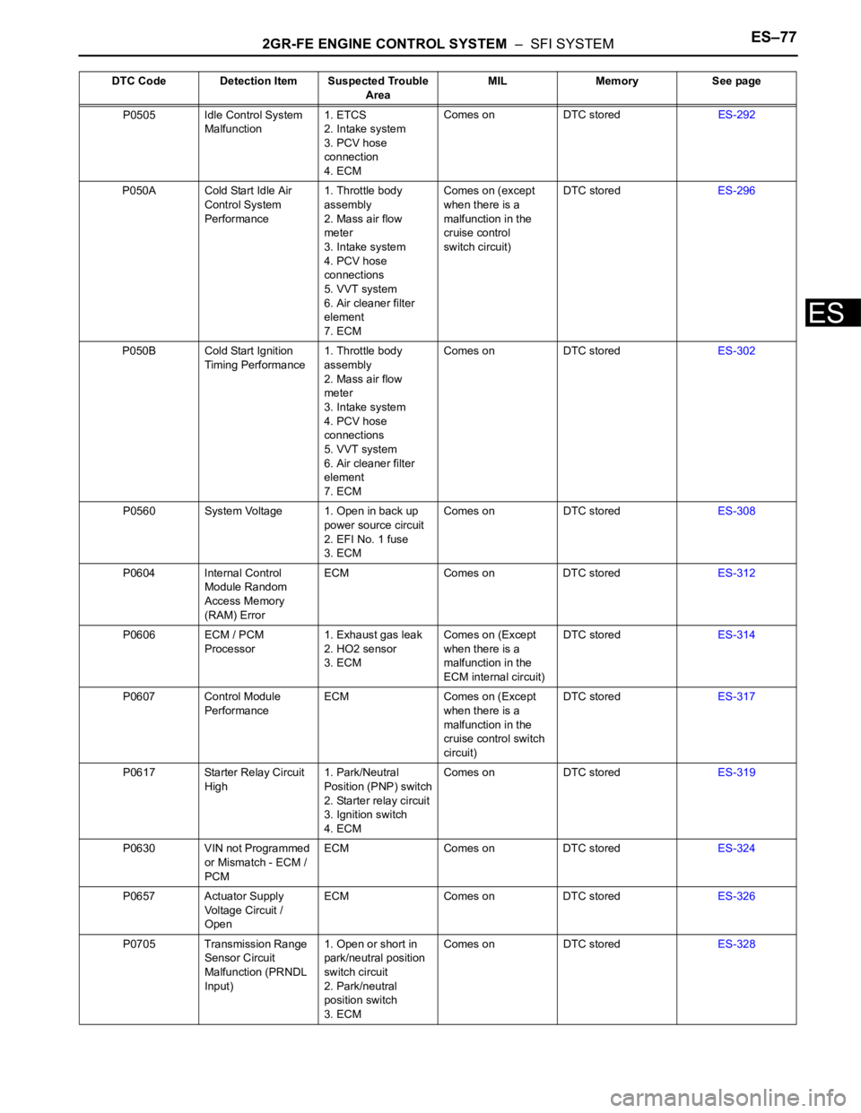
P0505 Idle Control System
Malfunction1. ETCS
2. Intake system
3. PCV hose
connection
4. ECMComes on DTC storedES-292
P050A Cold Start Idle Air
Control System
Performance1. Throttle body
assembly
2. Mass air flow
meter
3. Intake system
4. PCV hose
connections
5. VVT system
6. Air cleaner filter
element
7. ECMComes on (except
when there is a
malfunction in the
cruise control
switch circuit)DTC storedES-296
P050B Cold Start Ignition
Timing Performance1. Throttle body
assembly
2. Mass air flow
meter
3. Intake system
4. PCV hose
connections
5. VVT system
6. Air cleaner filter
element
7. ECMComes on DTC storedES-302
P0560 System Voltage 1. Open in back up
power source circuit
2. EFI No. 1 fuse
3. ECMComes on DTC storedES-308
P0604 Internal Control
Module Random
Access Memory
(RAM) ErrorECM Comes on DTC storedES-312
P0606 ECM / PCM
Processor1. Exhaust gas leak
2. HO2 sensor
3. ECMComes on (Except
when there is a
malfunction in the
ECM internal circuit)DTC storedES-314
P0607 Control Module
PerformanceECM Comes on (Except
when there is a
malfunction in the
cruise control switch
circuit)DTC storedES-317
P0617 Starter Relay Circuit
High1. Park/Neutral
Position (PNP) switch
2. Starter relay circuit
3. Ignition switch
4. ECMComes on DTC storedES-319
P0630 VIN not Programmed
or Mismatch - ECM /
PCMECM Comes on DTC storedES-324
P0657 Actuator Supply
Voltage Circuit /
OpenECM Comes on DTC storedES-326
P0705 Transmission Range
Sensor Circuit
Malfunction (PRNDL
Input)1. Open or short in
park/neutral position
switch circuit
2. Park/neutral
position switch
3. ECMComes on DTC storedES-328 DTC Code Detection Item Suspected Trouble
AreaMIL Memory See page