2007 TOYOTA SIENNA low idle
[x] Cancel search: low idlePage 2544 of 3000

BC–178BRAKE CONTROL – BRAKE ACTUATOR (w/ VSC)
BC
ON-VEHICLE INSPECTION
1. CONNECT INTELLIGENT TESTER
(a) Connect the intelligent tester to the DLC3.
(b) Start the engine and run at idle.
(c) Select the ACTIVE TEST mode on the intelligent
tester.
HINT:
Please refer to the intelligent tester operator's
manual for further details.
2. INSPECT ACTUATOR MOTOR OPERATION
(a) With the motor relay on, check the actuator motor
operation noise.
(b) Turn the motor relay off.
(c) Depress the brake pedal and hold it for
approximately 15 seconds. Check that the brake
pedal cannot be depressed.
(d) With the motor relay on, check that the pedal does
not pulsate.
NOTICE:
Do not keep the motor relay turned on for more
than 5 seconds continuously. When operating it
continuously, set an interval of more than 20
seconds.
(e) Turn the motor relay off and release the brake
pedal.
3. INSPECT RIGHT FRONT WHEEL OPERATION
NOTICE:
Never turn on the solenoids in a manner different to
those described below.
(a) With the brake pedal depressed, perform the
following operations.
(b) Turn the SFRH and SFRR solenoids on
simultaneously, and check that the pedal cannot be
depressed.
NOTICE:
Do not keep the solenoid turned on for more
than 10 seconds continuously. When operating
it continuously, set an interval of more than 20
seconds.
(c) Turn the SFRH and SFRR solenoids off
simultaneously, and check that the pedal can be
depressed.
(d) Turn the motor relay on, and check that the pedal
returns.
NOTICE:
Do not keep the motor relay turned on for more
than 5 seconds continuously. When operating it
continuously, set an interval of more than 20
seconds.
(e) Turn the motor relay off and release the brake
pedal.
A080036E03
Page 2555 of 3000

BRAKE CONTROL – BRAKE ACTUATOR (w/o VSC)BC–183
BC
ON-VEHICLE INSPECTION
1. CONNECT INTELLIGENT TESTER
(a) Connect the intelligent tester to the DLC3.
(b) Start the engine and run at idle.
(c) Select the ACTIVE TEST mode on the intelligent
tester.
HINT:
Please refer to the intelligent tester operator's
manual for further details.
2. INSPECT ACTUATOR MOTOR OPERATION
(a) With the motor relay on, check the actuator motor
operation noise.
(b) Turn the motor relay off.
(c) Depress the brake pedal and hold it for
approximately 15 seconds. Check that the brake
pedal cannot be depressed.
(d) With the motor relay on, check that the pedal does
not pulsate.
NOTICE:
Do not keep the motor relay turned on for more
than 5 seconds continuously. When operating it
continuously, set an interval of more than 20
seconds.
(e) Turn the motor relay off and release the brake
pedal.
3. INSPECT RIGHT FRONT WHEEL OPERATION
NOTICE:
Never turn on the solenoids in a manner different to
those described below.
(a) With the brake pedal depressed, perform the
following operations.
(b) Turn the SFRH and SFRR solenoids on
simultaneously, and check that the pedal cannot be
depressed.
NOTICE:
Do not keep the solenoid turned on for more
than 10 seconds continuously. When operating
it continuously, set an interval of more than 20
seconds.
(c) Turn the SFRH and SFRR solenoids off
simultaneously, and check that the pedal can be
depressed.
(d) Turn the motor relay on, and check that the pedal
returns.
NOTICE:
Do not keep the motor relay turned on for more
than 5 seconds continuously. When operating it
continuously, set an interval of more than 20
seconds.
(e) Turn the motor relay off and release the brake
pedal.
A080036E03
Page 2714 of 3000

PS–4POWER STEERING – POWER STEERING SYSTEM
PS
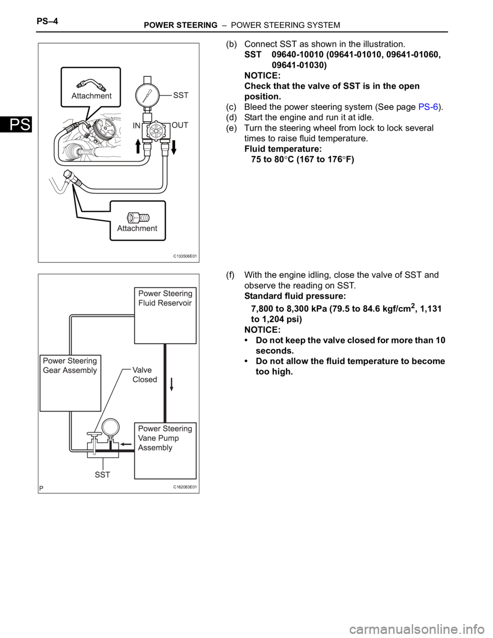
(b) Connect SST as shown in the illustration.
SST 09640-10010 (09641-01010, 09641-01060,
09641-01030)
NOTICE:
Check that the valve of SST is in the open
position.
(c) Bleed the power steering system (See page PS-6).
(d) Start the engine and run it at idle.
(e) Turn the steering wheel from lock to lock several
times to raise fluid temperature.
Fluid temperature:
75 to 80
C (167 to 176F)
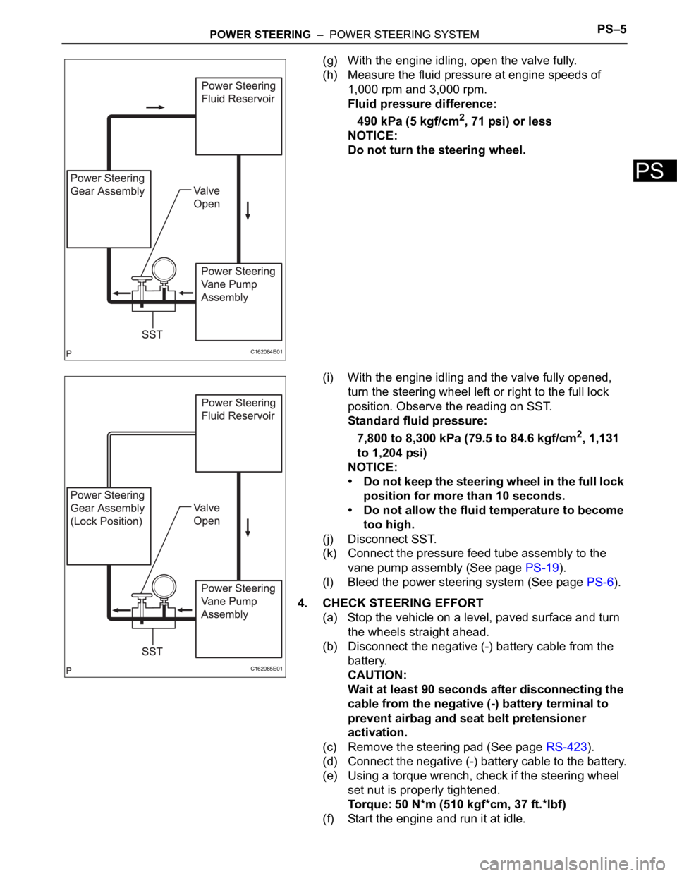
(f) With the engine idling, close the valve of SST and
observe the reading on SST.
Standard fluid pressure:
7,800 to 8,300 kPa (79.5 to 84.6 kgf/cm
2, 1,131
to 1,204 psi)
NOTICE:
• Do not keep the valve closed for more than 10
seconds.
• Do not allow the fluid temperature to become
too high.
C133506E01
C162083E01
Page 2715 of 3000

POWER STEERING – POWER STEERING SYSTEMPS–5
PS
(g) With the engine idling, open the valve fully.
(h) Measure the fluid pressure at engine speeds of
1,000 rpm and 3,000 rpm.
Fluid pressure difference:
490 kPa (5 kgf/cm
2, 71 psi) or less
NOTICE:
Do not turn the steering wheel.
(i) With the engine idling and the valve fully opened,
turn the steering wheel left or right to the full lock
position. Observe the reading on SST.
Standard fluid pressure:
7,800 to 8,300 kPa (79.5 to 84.6 kgf/cm
2, 1,131
to 1,204 psi)
NOTICE:
• Do not keep the steering wheel in the full lock
position for more than 10 seconds.
• Do not allow the fluid temperature to become
too high.
(j) Disconnect SST.
(k) Connect the pressure feed tube assembly to the
vane pump assembly (See page PS-19).
(l) Bleed the power steering system (See page PS-6).
4. CHECK STEERING EFFORT
(a) Stop the vehicle on a level, paved surface and turn
the wheels straight ahead.
(b) Disconnect the negative (-) battery cable from the
battery.
CAUTION:
Wait at least 90 seconds after disconnecting the
cable from the negative (-) battery terminal to
prevent airbag and seat belt pretensioner
activation.
(c) Remove the steering pad (See page RS-423).
(d) Connect the negative (-) battery cable to the battery.
(e) Using a torque wrench, check if the steering wheel
set nut is properly tightened.
Torque: 50 N*m (510 kgf*cm, 37 ft.*lbf)
(f) Start the engine and run it at idle.
C162084E01
C162085E01
Page 2717 of 3000

PS–6POWER STEERING – POWER STEERING FLUID
PS
POWER STEERING FLUID
BLEEDING
1. BLEED POWER STEERING SYSTEM
(a) Check the fluid level (See page PS-2).
(b) Jack up the front of the vehicle and support it with
stands.
(c) Turn the steering wheel.
(1) With the engine stopped, turn the steering
wheel slowly from lock to lock several times.
(d) Lower the vehicle.
(e) Start the engine.
(1) Run the engine at idle for a few minutes.
(f) Turn the steering wheel.
(1) With the engine idling, turn the steering wheel
left or right to the full lock position and keep it in
that position for 2 to 3 seconds, then turn the
steering wheel to the opposite full lock position
and keep it there for 2 to 3 seconds.
(2) Repeat this procedure several times.
(g) Stop the engine.
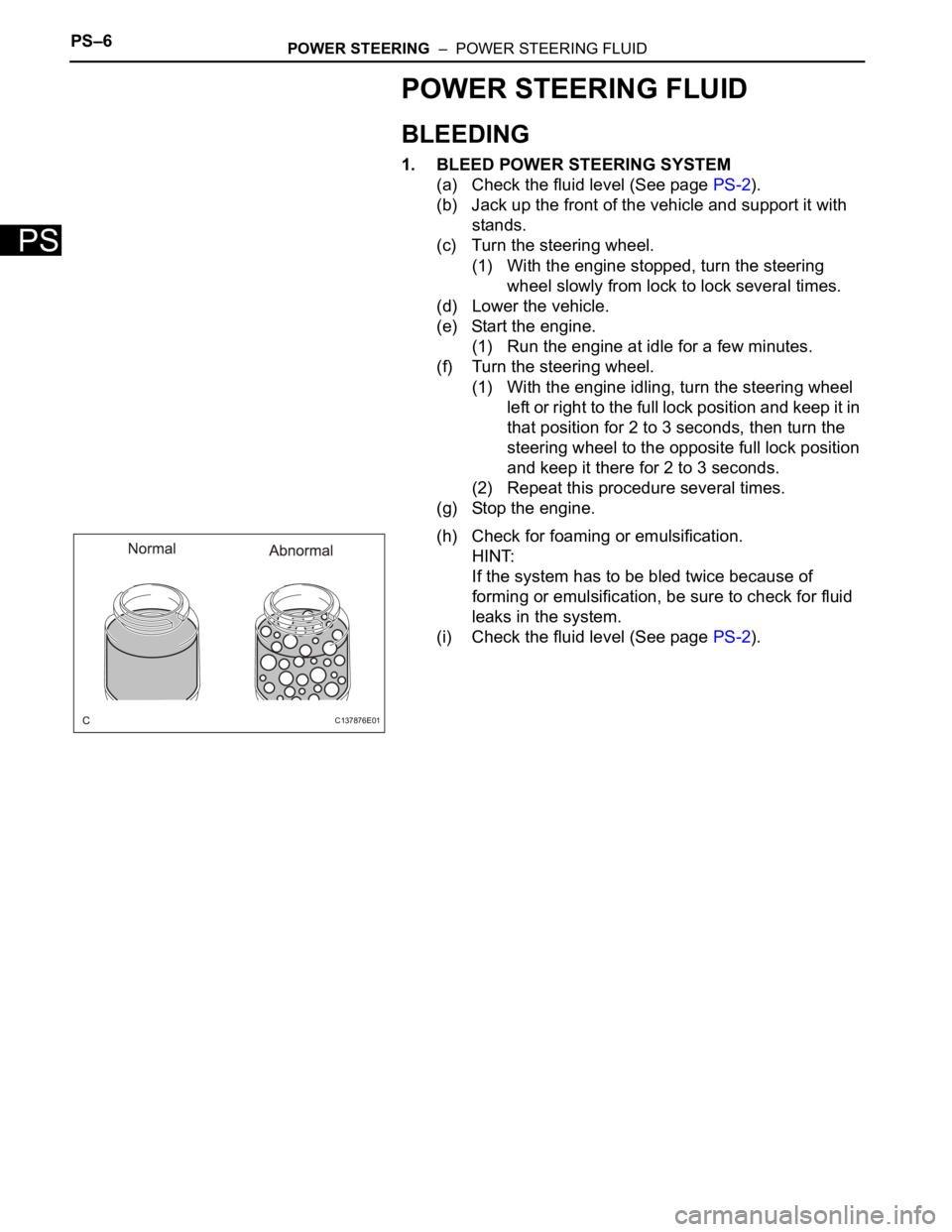
(h) Check for foaming or emulsification.
HINT:
If the system has to be bled twice because of
forming or emulsification, be sure to check for fluid
leaks in the system.
(i) Check the fluid level (See page PS-2).
C137876E01
Page 2757 of 3000

AIR CONDITIONING – AIR CONDITIONING SYSTEM (for Automatic Air Conditioning Sys-
tem)AC–9
AC
Rear A/C:
No air inlet controlAir inlet damper control servo motor circuitAC-98
Air inlet damper position sensor circuitAC-73
A/C amplifierAC-253
No air outlet controlAir outlet damper position sensor circuitAC-77
Air outlet control servo motor circuitAC-103
A/C amplifierAC-253
Engine idle up does not occur, or is continuousCompressor circuitAC-134
A/C amplifierAC-253
Displayed set temperature value does not match up
with operation of temperature control switchA/C amplifierAC-253
Brightness does not change when rheostat volume or
light control switch is turnedA/C amplifierAC-253
Unable to access the diagnosis mode A/C amplifierAC-253
DTC is not recorded. Set mode is cleared when IG
switch is turned offBack-up power source circuitAC-154
A/C amplifierAC-253
Symptom Suspected Area See page
Whole functions of the A/C system do not operateA/C amplifierAC-253
Rear air conditioning relay circuitAC-142
Rear air conditioning control panel circuitAC-139
Air Flow Control: No blower operationRear blower motor circuitAC-144
A/C amplifierAC-253
Air Flow Control: No blower controlRear blower motor circuitAC-144
A/C amplifierAC-253
Air Flow Control: Insufficient air outRear blower motor circuitAC-144
A/C amplifierAC-253
Temperature Control: Cool air does not come outVolume of refrigerantAC-168
Drive belt tension -
Refrigerant pressureAC-168
Compressor circuitAC-134
Pressure sensor circuitAC-51
Ambient temperature sensor circuitAC-28
Rear evaporator temperature sensor circuitAC-35
A/C amplifierAC-253
Temperature Control: Warm air does not come outRear air mix control servo motor circuitAC-113
Rear air mix damper position sensor circuitAC-85
Ambient temperature sensor circuitAC-28
Rear room temperature sensor circuitAC-39
Rear evaporator temperature sensor circuitAC-35
A/C amplifierAC-253
Heater radiatorAC-187
Temperature Control: Output air is warmer or cooler
than the set temperature or response is slowRear room temperature sensor circuitAC-39
Ambient temperature sensor circuitAC-28
Rear air mix damper position sensor circuitAC-85
Rear air mix control servo motor circuitAC-113
A/C amplifierAC-253
Temperature Control: No temperature control (only
Max. cool or Max. hot)Rear air mix control servo motor circuitAC-113
Rear air mix damper position sensor circuitAC-85
A/C amplifierAC-253 Symptom Suspected Area See page
Page 2763 of 3000

AIR CONDITIONING – AIR CONDITIONING SYSTEM (for Automatic Air Conditioning Sys-
tem)AC–9
AC
Rear A/C:
No air inlet controlAir inlet damper control servo motor circuitAC-98
Air inlet damper position sensor circuitAC-73
A/C amplifierAC-253
No air outlet controlAir outlet damper position sensor circuitAC-77
Air outlet control servo motor circuitAC-103
A/C amplifierAC-253
Engine idle up does not occur, or is continuousCompressor circuitAC-134
A/C amplifierAC-253
Displayed set temperature value does not match up
with operation of temperature control switchA/C amplifierAC-253
Brightness does not change when rheostat volume or
light control switch is turnedA/C amplifierAC-253
Unable to access the diagnosis mode A/C amplifierAC-253
DTC is not recorded. Set mode is cleared when IG
switch is turned offBack-up power source circuitAC-154
A/C amplifierAC-253
Symptom Suspected Area See page
Whole functions of the A/C system do not operateA/C amplifierAC-253
Rear air conditioning relay circuitAC-142
Rear air conditioning control panel circuitAC-139
Air Flow Control: No blower operationRear blower motor circuitAC-144
A/C amplifierAC-253
Air Flow Control: No blower controlRear blower motor circuitAC-144
A/C amplifierAC-253
Air Flow Control: Insufficient air outRear blower motor circuitAC-144
A/C amplifierAC-253
Temperature Control: Cool air does not come outVolume of refrigerantAC-168
Drive belt tension -
Refrigerant pressureAC-168
Compressor circuitAC-134
Pressure sensor circuitAC-51
Ambient temperature sensor circuitAC-28
Rear evaporator temperature sensor circuitAC-35
A/C amplifierAC-253
Temperature Control: Warm air does not come outRear air mix control servo motor circuitAC-113
Rear air mix damper position sensor circuitAC-85
Ambient temperature sensor circuitAC-28
Rear room temperature sensor circuitAC-39
Rear evaporator temperature sensor circuitAC-35
A/C amplifierAC-253
Heater radiatorAC-187
Temperature Control: Output air is warmer or cooler
than the set temperature or response is slowRear room temperature sensor circuitAC-39
Ambient temperature sensor circuitAC-28
Rear air mix damper position sensor circuitAC-85
Rear air mix control servo motor circuitAC-113
A/C amplifierAC-253
Temperature Control: No temperature control (only
Max. cool or Max. hot)Rear air mix control servo motor circuitAC-113
Rear air mix damper position sensor circuitAC-85
A/C amplifierAC-253 Symptom Suspected Area See page