2007 TOYOTA SIENNA low idle
[x] Cancel search: low idlePage 425 of 3000

2GR-FE ENGINE CONTROL SYSTEM – SFI SYSTEMES–119
ES
TYPICAL ENABLING CONDITIONS
All:
P0037 and P0057:
P0038 and P0058 Case 1:
P0038 and P0058 Case 2:
P0141 and P0161:
TYPICAL MALFUNCTION THRESHOLDS
P0037 and P0057:
P0038 and P0058:
P0141 and P0161 (Heater performance monitor check):
COMPONENT OPERATING RANGE
MONITOR RESULT
Refer to CHECKING MONITOR STATUS (See page ES-19).
WIRING DIAGRAM
Refer to DTC P0136 (See page ES-167).
INSPECTION PROCEDURE
HINT:
• If other DTCs relating to different systems that have terminal E2 as the ground terminal are output
simultaneously, terminal E2 may have an open circuit.
Monitor runs whenever following DTCs are not present None
Battery voltage 10.5 to 20 V
Battery voltage 10.5 V or more
Engine Running
Sta r t e r OF F
Battery voltage 10.5 to 20 V
One of the following conditions is met: Condition A or B
A. All of the following conditions are met: Conditions 1, 2, 3, 4 and 5
1. Battery voltage 10.5 V or more
2. Fuel cut OFF
3. Time after fuel cut ON to OFF 30 seconds or more
4. Accumulated heater ON time 100 seconds or more
5. Learned heater OFF current operation Completed
B. Duration that rear heated oxygen sensor impedance is less than 15
k
2 seconds or more
Heater Current - Learned heater OFF current Less than 0.3 A
Learned heater OFF current More than 2 A
Heater Current - Learned heater OFF current 2 A or more
Accumulated heater resistance Varies with sensor element temperature (Example: More than 23
)
Heated Oxygen (HO2) sensor heater current0.4 to 1 A (when engine idles, HO2 sensor warmed up and battery voltage 11 to 14
V)
Page 429 of 3000
2GR-FE ENGINE CONTROL SYSTEM – SFI SYSTEMES–123
ES
OK
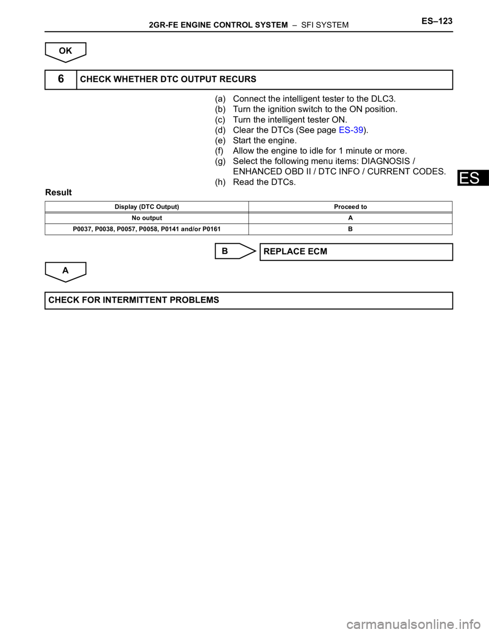
(a) Connect the intelligent tester to the DLC3.
(b) Turn the ignition switch to the ON position.
(c) Turn the intelligent tester ON.
(d) Clear the DTCs (See page ES-39).
(e) Start the engine.
(f) Allow the engine to idle for 1 minute or more.
(g) Select the following menu items: DIAGNOSIS /
ENHANCED OBD II / DTC INFO / CURRENT CODES.
(h) Read the DTCs.
Result
B
A
6CHECK WHETHER DTC OUTPUT RECURS
Display (DTC Output) Proceed to
No output A
P0037, P0038, P0057, P0058, P0141 and/or P0161 B
REPLACE ECM
CHECK FOR INTERMITTENT PROBLEMS
Page 465 of 3000
2GR-FE ENGINE CONTROL SYSTEM – SFI SYSTEMES–159
ES
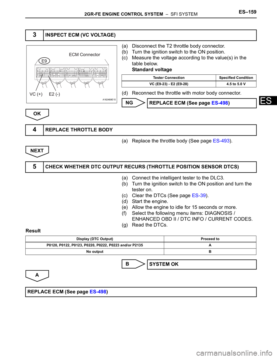
(a) Disconnect the T2 throttle body connector.
(b) Turn the ignition switch to the ON position.
(c) Measure the voltage according to the value(s) in the
table below.
Standard voltage
(d) Reconnect the throttle with motor body connector.
NG
OK
(a) Replace the throttle body (See page ES-493).
NEXT
(a) Connect the intelligent tester to the DLC3.
(b) Turn the ignition switch to the ON position and turn the
tester on.
(c) Clear the DTCs (See page ES-39).
(d) Start the engine.
(e) Allow the engine to idle for 15 seconds or more.
(f) Select the following menu items: DIAGNOSIS /
ENHANCED OBD II / DTC INFO / CURRENT CODES.
(g) Read the DTCs.
Result
B
A
3INSPECT ECM (VC VOLTAGE)
A162489E15
Tester Connection Specified Condition
VC (E9-23) - E2 (E9-28) 4.5 to 5.0 V
REPLACE ECM (See page ES-498)
4REPLACE THROTTLE BODY
5CHECK WHETHER DTC OUTPUT RECURS (THROTTLE POSITION SENSOR DTCS)
Display (DTC Output) Proceed to
P0120, P0122, P0123, P0220, P0222, P0223 and/or P2135 A
No output B
SYSTEM OK
REPLACE ECM (See page ES-498)
Page 479 of 3000

2GR-FE ENGINE CONTROL SYSTEM – SFI SYSTEMES–173
ES
TYPICAL ENABLING CONDITIONS
All:
Heated Oxygen Sensor Output Voltage (Output Voltage, High Voltage and Low Voltage):
Heated Oxygen Sensor Impedance (Low):
Heated Oxygen Sensor Impedance (High):
Heated Oxygen Sensor Output Voltage (Extremely High):
TYPICAL MALFUNCTION THRESHOLDS
Heated Oxygen Sensor Output Voltage (Output voltage):
Heated Oxygen Sensor Output Voltage (Low output voltage):
The monitor will run whenever these DTCs are not
presentP0031, P0032, P0051, P0052 (A/F Sensor Heater Sensor 1), P0100, P0101, P0102,
P0103 (MAF Sensor), P0110, P0112, P0113 (IAT Sensor), P0115, P0116, P0117,
P0118 (ECT Sensor), P0120, P0121, P0122, P0123, P0220, P0222, P0223, P2135
(TP Sensor), P0125 (Insufficient ECT for Closed Loop), P0171, P0172 (Fuel
System), P0300, P0301, P0302, P0303, P0304, P0305, P0306 (Misfire), P0335
(CKP Sensor), P0340 (CMP Sensor), P0500 (VSS), P2196, P2198 (A/F Sensor
(Rationality)), P2A00, P2A03 (A/F Sensor (Slow Response))
Active air-fuel ratio control Performing
Active air-fuel ratio control is performed when the
following conditions are met:-
Battery voltage 11 V or more
Engine coolant temperature 75
C (167F) or more
Idle OFF
Engine RPM Less than 3200 rpm
A/F sensor status Activated
Fuel system status Closed loop
Fuel-cut OFF
Engine load 10 to 70%
Shift position 4th or more
Battery voltage 11 V or more
Estimated HO2S temperature Less than 700
C (1292F)
ECM monitor Completed
DTC P0606 Not set
Battery voltage 11 V or more
Estimated HO2S temperature 450
C (842F) or more
DTC P0606 Not set
Battery voltage 11 V or more
Time after engine start 2 seconds or more
Either of the following conditions is met: 1 or 2
1. All of the following conditions (a), (b) and (c) are met -
(a) Commanded air-fuel ratio 14.3 or less
(b) Rear HO2 sensor voltage 0.21 to 0.59 V
(c) OSC (Oxygen Storage Capacity of Catalyst) 2.0 g (0.0044 lb) or more
2. All of the following conditions (d), (f) and (g) are met. -
(d) Commanded air-fuel ratio 14.9 or more
(f) Rear HO2 sensor voltage 0.21 to 0.59 V
(g) OSC 2.0 g (0.0044 lb) or more
All of the following conditions (a), (b) and (c) are met. -
(a) Commanded air-fuel ratio 14.3 or less
Page 485 of 3000
2GR-FE ENGINE CONTROL SYSTEM – SFI SYSTEMES–179
ES
(b) Turn the ignition switch to the ON position and turn the
tester on.
(c) Select the following menu items: DIAGNOSIS /
ENHANCED OBD II / DTC INFO / CURRENT CODES.
(d) Read the DTCs.
Result
B
C
A
(a) Connect the intelligent tester to the DLC3.
(b) Turn the ignition switch to the ON position and turn the
tester on.
(c) Select the following menu items: DIAGNOSIS /
ENHANCED OBD II / DATA LIST / PRIMARY / O2S
B1S2 or O2S B2S2.
(d) Allow the engine to idle.
(e) Read the Heated Oxygen (HO2) sensor output voltage
while idling.
Result
B
A
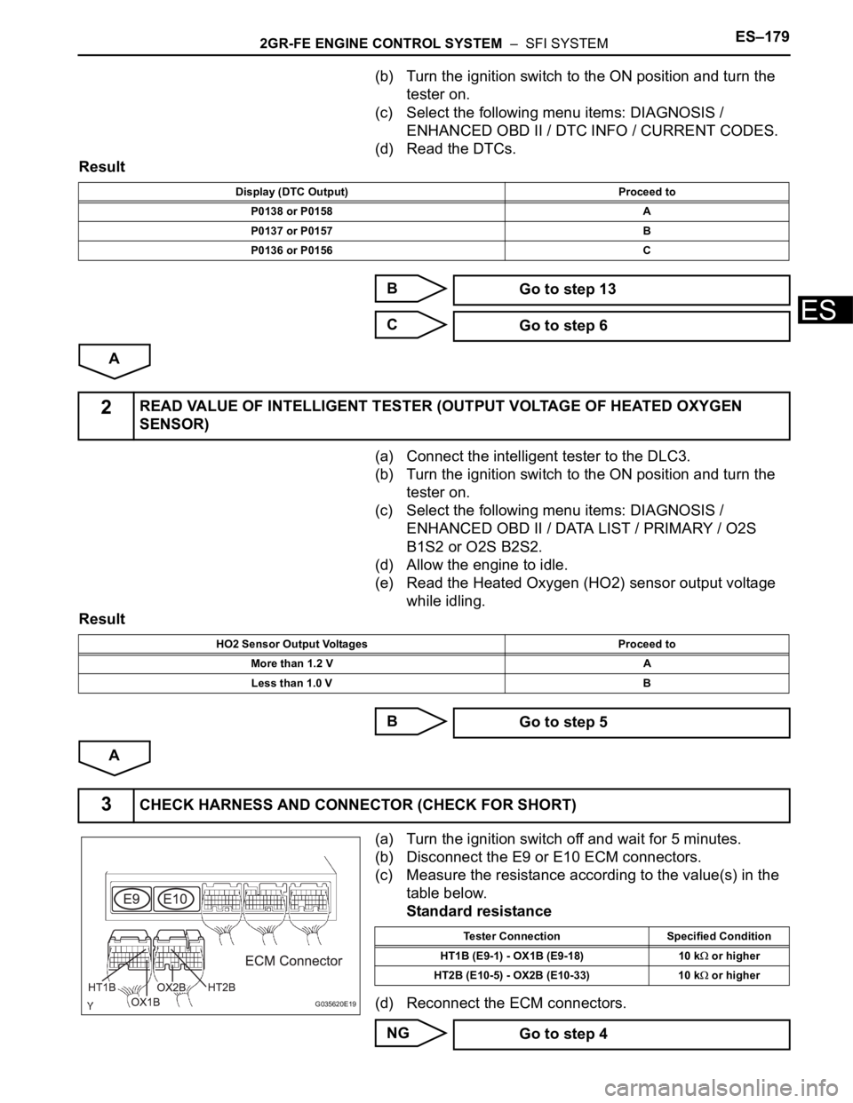
(a) Turn the ignition switch off and wait for 5 minutes.
(b) Disconnect the E9 or E10 ECM connectors.
(c) Measure the resistance according to the value(s) in the
table below.
Standard resistance
(d) Reconnect the ECM connectors.
NG
Display (DTC Output) Proceed to
P0138 or P0158 A
P0137 or P0157 B
P0136 or P0156 C
Go to step 13
Go to step 6
2READ VALUE OF INTELLIGENT TESTER (OUTPUT VOLTAGE OF HEATED OXYGEN
SENSOR)
HO2 Sensor Output Voltages Proceed to
More than 1.2 V A
Less than 1.0 V B
Go to step 5
3CHECK HARNESS AND CONNECTOR (CHECK FOR SHORT)
G035620E19
Tester Connection Specified Condition
HT1B (E9-1) - OX1B (E9-18) 10 k
or higher
HT2B (E10-5) - OX2B (E10-33) 10 k
or higher
Go to step 4
Page 500 of 3000
ES–1942GR-FE ENGINE CONTROL SYSTEM – SFI SYSTEM
ES
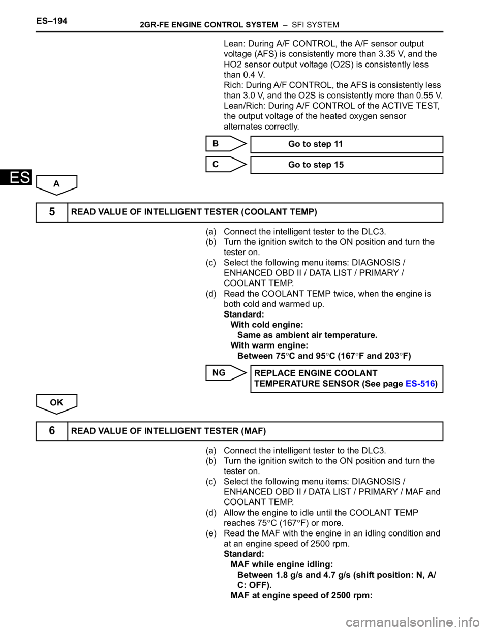
Lean: During A/F CONTROL, the A/F sensor output
voltage (AFS) is consistently more than 3.35 V, and the
HO2 sensor output voltage (O2S) is consistently less
than 0.4 V.
Rich: During A/F CONTROL, the AFS is consistently less
than 3.0 V, and the O2S is consistently more than 0.55 V.
Lean/Rich: During A/F CONTROL of the ACTIVE TEST,
the output voltage of the heated oxygen sensor
alternates correctly.
B
C
A
(a) Connect the intelligent tester to the DLC3.
(b) Turn the ignition switch to the ON position and turn the
tester on.
(c) Select the following menu items: DIAGNOSIS /
ENHANCED OBD II / DATA LIST / PRIMARY /
COOLANT TEMP.
(d) Read the COOLANT TEMP twice, when the engine is
both cold and warmed up.
Standard:
With cold engine:
Same as ambient air temperature.
With warm engine:
Between 75
C and 95C (167F and 203F)
NG
OK
(a) Connect the intelligent tester to the DLC3.
(b) Turn the ignition switch to the ON position and turn the
tester on.
(c) Select the following menu items: DIAGNOSIS /
ENHANCED OBD II / DATA LIST / PRIMARY / MAF and
COOLANT TEMP.
(d) Allow the engine to idle until the COOLANT TEMP
reaches 75
C (167F) or more.
(e) Read the MAF with the engine in an idling condition and
at an engine speed of 2500 rpm.
Standard:
MAF while engine idling:
Between 1.8 g/s and 4.7 g/s (shift position: N, A/
C: OFF).
MAF at engine speed of 2500 rpm: Go to step 11
Go to step 15
5READ VALUE OF INTELLIGENT TESTER (COOLANT TEMP)
REPLACE ENGINE COOLANT
TEMPERATURE SENSOR (See page ES-516)
6READ VALUE OF INTELLIGENT TESTER (MAF)
Page 516 of 3000
ES–2102GR-FE ENGINE CONTROL SYSTEM – SFI SYSTEM
ES
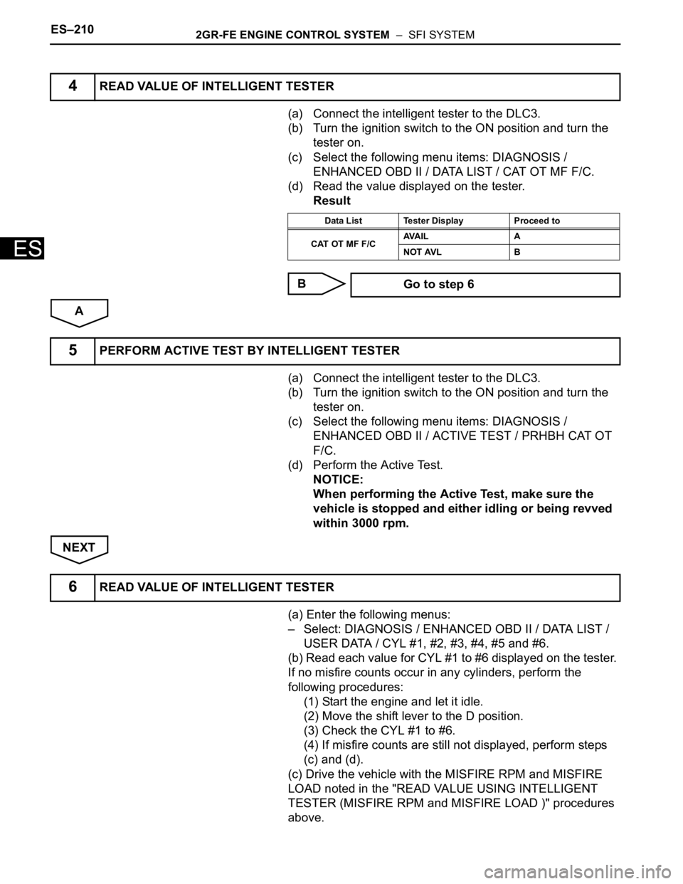
(a) Connect the intelligent tester to the DLC3.
(b) Turn the ignition switch to the ON position and turn the
tester on.
(c) Select the following menu items: DIAGNOSIS /
ENHANCED OBD II / DATA LIST / CAT OT MF F/C.
(d) Read the value displayed on the tester.
Result
B
A
(a) Connect the intelligent tester to the DLC3.
(b) Turn the ignition switch to the ON position and turn the
tester on.
(c) Select the following menu items: DIAGNOSIS /
ENHANCED OBD II / ACTIVE TEST / PRHBH CAT OT
F/C.
(d) Perform the Active Test.
NOTICE:
When performing the Active Test, make sure the
vehicle is stopped and either idling or being revved
within 3000 rpm.
NEXT
(a) Enter the following menus:
– Select: DIAGNOSIS / ENHANCED OBD II / DATA LIST /
USER DATA / CYL #1, #2, #3, #4, #5 and #6.
(b) Read each value for CYL #1 to #6 displayed on the tester.
If no misfire counts occur in any cylinders, perform the
following procedures:
(1) Start the engine and let it idle.
(2) Move the shift lever to the D position.
(3) Check the CYL #1 to #6.
(4) If misfire counts are still not displayed, perform steps
(c) and (d).
(c) Drive the vehicle with the MISFIRE RPM and MISFIRE
LOAD noted in the "READ VALUE USING INTELLIGENT
TESTER (MISFIRE RPM and MISFIRE LOAD )" procedures
above.
4READ VALUE OF INTELLIGENT TESTER
Data List Tester Display Proceed to
CAT OT MF F/CAVA I L A
NOT AVL B
Go to step 6
5PERFORM ACTIVE TEST BY INTELLIGENT TESTER
6READ VALUE OF INTELLIGENT TESTER
Page 521 of 3000
2GR-FE ENGINE CONTROL SYSTEM – SFI SYSTEMES–215
ES
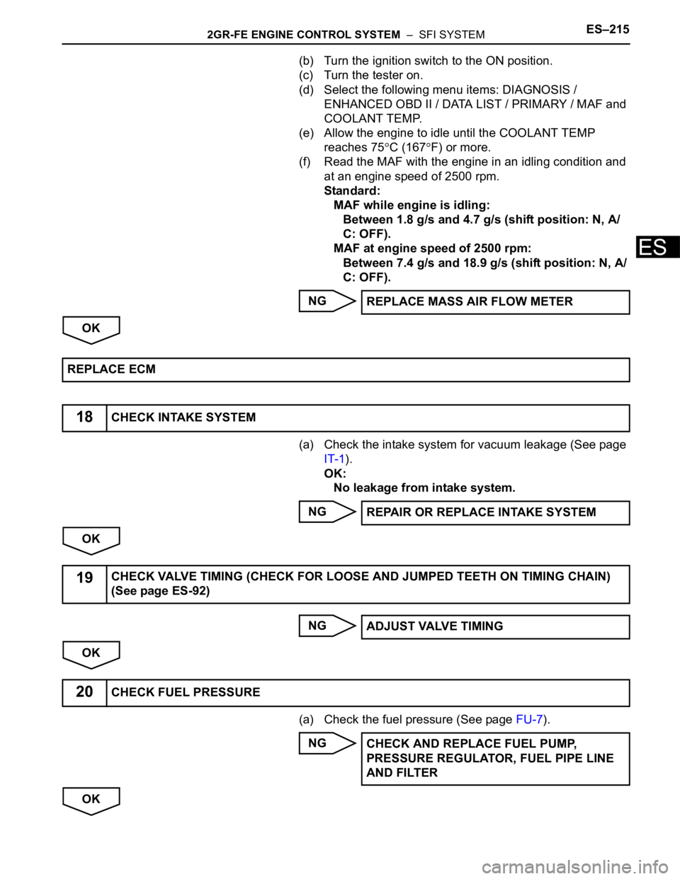
(b) Turn the ignition switch to the ON position.
(c) Turn the tester on.
(d) Select the following menu items: DIAGNOSIS /
ENHANCED OBD II / DATA LIST / PRIMARY / MAF and
COOLANT TEMP.
(e) Allow the engine to idle until the COOLANT TEMP
reaches 75
C (167F) or more.
(f) Read the MAF with the engine in an idling condition and
at an engine speed of 2500 rpm.
Standard:
MAF while engine is idling:
Between 1.8 g/s and 4.7 g/s (shift position: N, A/
C: OFF).
MAF at engine speed of 2500 rpm:
Between 7.4 g/s and 18.9 g/s (shift position: N, A/
C: OFF).
NG
OK
(a) Check the intake system for vacuum leakage (See page
IT-1).
OK:
No leakage from intake system.
NG
OK
NG
OK
(a) Check the fuel pressure (See page FU-7).
NG
OKREPLACE MASS AIR FLOW METER
REPLACE ECM
18CHECK INTAKE SYSTEM
REPAIR OR REPLACE INTAKE SYSTEM
19CHECK VALVE TIMING (CHECK FOR LOOSE AND JUMPED TEETH ON TIMING CHAIN)
(See page ES-92)
ADJUST VALVE TIMING
20CHECK FUEL PRESSURE
CHECK AND REPLACE FUEL PUMP,
PRESSURE REGULATOR, FUEL PIPE LINE
AND FILTER