2007 TOYOTA SIENNA low idle
[x] Cancel search: low idlePage 661 of 3000
ES–3682GR-FE ENGINE CONTROL SYSTEM – SFI SYSTEM
ES
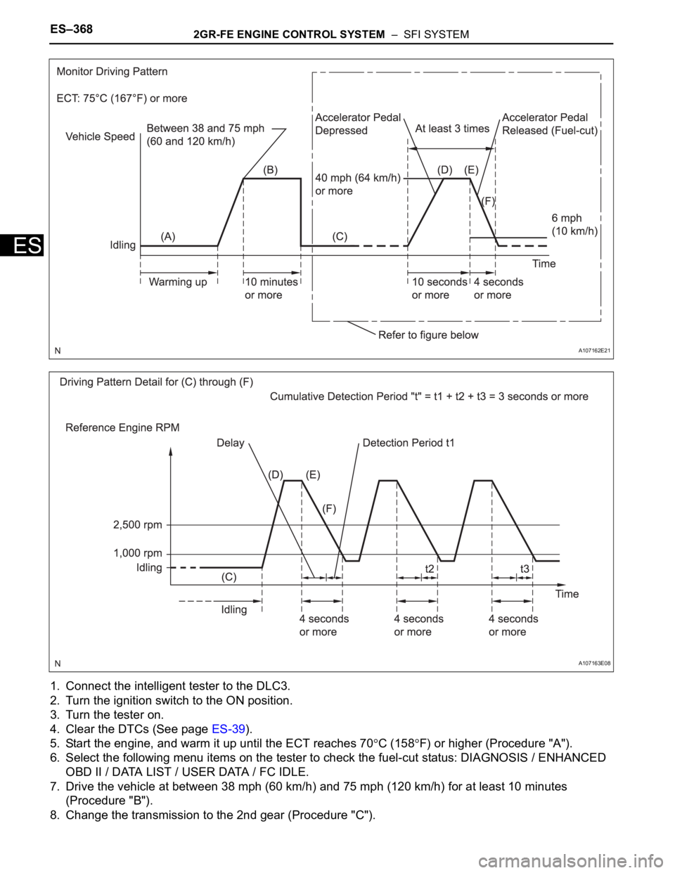
1. Connect the intelligent tester to the DLC3.
2. Turn the ignition switch to the ON position.
3. Turn the tester on.
4. Clear the DTCs (See page ES-39).
5. Start the engine, and warm it up until the ECT reaches 70
C (158F) or higher (Procedure "A").
6. Select the following menu items on the tester to check the fuel-cut status: DIAGNOSIS / ENHANCED
OBD II / DATA LIST / USER DATA / FC IDLE.
7. Drive the vehicle at between 38 mph (60 km/h) and 75 mph (120 km/h) for at least 10 minutes
(Procedure "B").
8. Change the transmission to the 2nd gear (Procedure "C").
A107162E21
A107163E08
Page 690 of 3000
2GR-FE ENGINE CONTROL SYSTEM – SFI SYSTEMES–397
ES
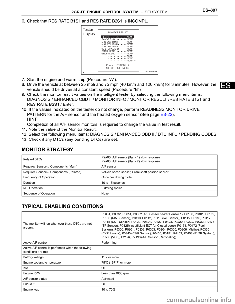
6. Check that RES RATE B1S1 and RES RATE B2S1 is INCOMPL.
7. Start the engine and warm it up (Procedure "A").
8. Drive the vehicle at between 25 mph and 75 mph (40 km/h and 120 km/h) for 3 minutes. However, the
vehicle should be driven at a constant speed (Procedure "B").
9. Check the monitor result values on the intelligent tester by selecting the following menu items:
DIAGNOSIS / ENHANCED OBD II / MONITOR INFO / MONITOR RESULT /RES RATE B1S1 and
RES RATE B2S1 / Enter.
10. If the values indicated on the tester do not change, perform READINESS MONITOR DRIVE
PATTERN for the A/F sensor and the heated oxygen sensor (See page ES-22).
HINT:
Completion of all A/F sensor monitors is required to change the value in test result.
11. Note the value of the Monitor Result.
12. Select the following menu items: DIAGNOSIS / ENHANCED OBD II / DTC INFO / PENDING CODES.
13. Check if any DTCs (any pending DTCs) are set.
MONITOR STRATEGY
TYPICAL ENABLING CONDITIONS
Related DTCsP2A00: A/F sensor (Bank 1) slow response
P2A03: A/F sensor (Bank 2) slow response
Required Sensors / Components (Main) A/F sensor
Required Sensors / Components (Related) Vehicle speed sensor, Crankshaft position sensor
Frequency of Operation Once per driving cycle
Duration 10 to 15 seconds
MIL Operation 2 driving cycles
Sequence of Operation None
The monitor will run whenever these DTCs are not
presentP0031, P0032, P0051, P0052 (A/F Sensor heater Sensor 1), P0100, P0101, P0102,
P0103 (MAF Sensor), P0110, P0112, P0113 (IAT Sensor), P0115, P0116, P0117,
P0118 (ECT Sensor), P0120, P0121, P0122, P0123, P0220, P0222, P0223, P2135
(TP Sensor), P0125 (Insufficient ECT for Closed Loop), P0171, P0172 (Fuel
System), P0300, P0301, P0302, P0303, P0304, P0305, P0306 (Misfire), P0335
(CKP Sensor), P0340 (CMP Sensor), P0450, P0451, P0452, P0453 (EVAP System),
P0500 (VSS), P2196, P2198 (A/F Sensor (Rationality))
Active A/F control Performing
Active A/F control is performed when the following
conditions are met-
Battery voltage 11 V or more
Engine coolant temperature 75
C (167F) or more
Idle OFF
Engine RPM Less than 4000 rpm
A/F sensor status Activated
Fuel-cut OFF
Engine load 10 to 70%
G034992E04
Page 699 of 3000
2GR-FE ENGINE CONTROL SYSTEM – SFI SYSTEMES–413
ES
NOTICE:
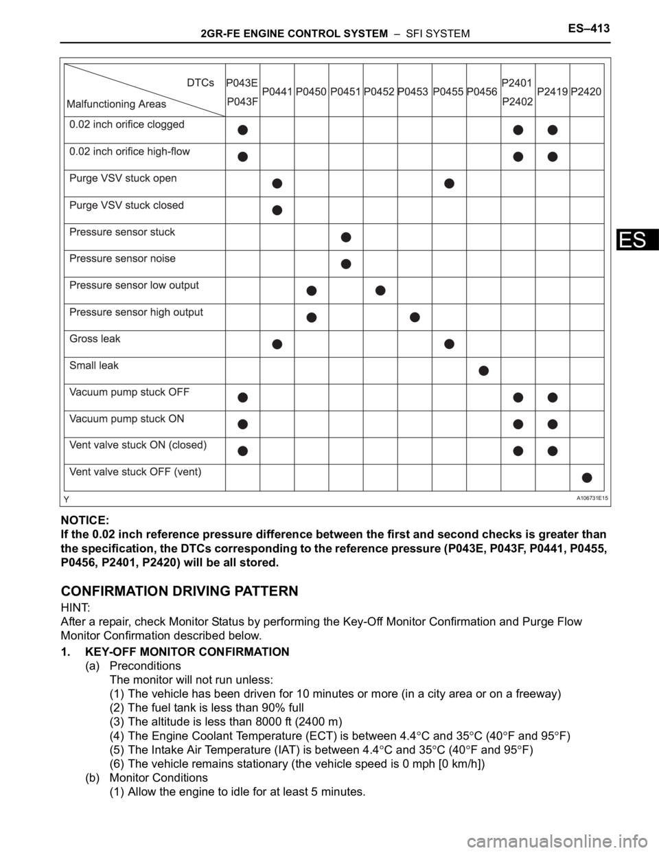
If the 0.02 inch reference pressure difference between the first and second checks is greater than
the specification, the DTCs corresponding to the reference pressure (P043E, P043F, P0441, P0455,
P0456, P2401, P2420) will be all stored.
CONFIRMATION DRIVING PATTERN
HINT:
After a repair, check Monitor Status by performing the Key-Off Monitor Confirmation and Purge Flow
Monitor Confirmation described below.
1. KEY-OFF MONITOR CONFIRMATION
(a) Preconditions
The monitor will not run unless:
(1) The vehicle has been driven for 10 minutes or more (in a city area or on a freeway)
(2) The fuel tank is less than 90% full
(3) The altitude is less than 8000 ft (2400 m)
(4) The Engine Coolant Temperature (ECT) is between 4.4
C and 35C (40F and 95F)
(5) The Intake Air Temperature (IAT) is between 4.4
C and 35C (40F and 95F)
(6) The vehicle remains stationary (the vehicle speed is 0 mph [0 km/h])
(b) Monitor Conditions
(1) Allow the engine to idle for at least 5 minutes.
A106731E15
Page 700 of 3000

ES–4142GR-FE ENGINE CONTROL SYSTEM – SFI SYSTEM
ES
(2) Turn the ignition switch off and wait for 6 hours (8 or 10.5 hours).
HINT:
Do not start the engine until checking MONITOR STATUS. If the engine is started, the steps
described above must be repeated.
(c) Monitor Status
(1) Connect the intelligent tester to the DLC3.
(2) Turn the ignition switch to the ON position and turn the tester on.
(3) Select the following menu items: DIAGNOSIS / ENHANCED OBD II / MONITOR STATUS.
(4) Check the "Monitor Status" displayed on the tester.
HINT:
If INCMP is displayed, the monitor is not completed. Make sure that the preconditions have
been met, and perform "Monitor Conditions" again.
2. PURGE FLOW MONITOR CONFIRMATION (P0441)
HINT:
Perform this monitor confirmation after the Key-Off Monitor Confirmation shows COMPL (complete).
(a) Preconditions
The monitor will not run unless:
• The vehicle has been driven for 10 minutes or more (in a city area or on a freeway)
• The ECT is between 4.4
C and 35C (40F and 95F)
• The IAT is between 4.4
C and 35C (40F and 95F)
(b) Monitor Conditions
(1) Release the pressure from the fuel tank by removing and reinstalling the fuel tank cap.
(2) Warm the engine up until the ECT reaches more than 75
C (167F).
(3) Increase the engine speed to 3000 rpm once.
(4) Allow the engine to idle and turn the A/C ON for 1 minute.
(c) Monitor Status
(1) Turn the ignition switch off.
(2) Connect the intelligent tester to the DLC3.
(3) Turn the ignition switch to the ON position and turn the tester on.
(4) Select the following menu items: DIAGNOSIS / ENHANCED OBD II / MONITOR STATUS.
(5) Check the "Monitor Status" displayed on the tester.
HINT:
If INCMP is displayed, the monitor is not completed. Make sure that the preconditions have
been met, and perform "Monitor Conditions" again.
MONITOR RESULT
Refer to Checking Monitor Status for detailed information (See page ES-19).
The test value and test limit information are described as shown in the following table. This information is
included in MONITOR RESULT of the emissions-related DTC sections:
– MID (Monitor Identification Data) is assigned to each emissions-related component.
– TID (Test Identification Data) is assigned to each test value.
– Scaling is used to calculate the test value indicated on generic OBD II scan tools.
Thermostat
MID TID Scaling Description of Test Value Minimum Test Limit Maximum Test Limit
$3D $C9 Multiply by 0.01 [kPa]Test value for small leak (P0456)
Refer to pressure D*Minimum test limit for
small leakMaximum test limit for
small leak
$3D $CA Multiply by 0.01 [kPa]Test value for gross leak (P0455)
Refer to pressure E*Minimum test limit for
gross leakMaximum test limit for
gross leak
$3D $CB Multiply by 0.01 [kPa]Test value for vacuum pump stuck OFF
(P2401)
Refer to pressure A*Minimum test limit for
vacuum pump stuck
OFFMaximum test limit for
vacuum pump stuck
OFF
$3D $CD Multiply by 0.01 [kPa]Test value for vacuum pump stuck ON
(P2402)
Refer to pressure A*Minimum test limit for
vacuum pump stuck
ONMaximum test limit for
vacuum pump stuck
ON
Page 806 of 3000

ES–302GR-FE ENGINE CONTROL SYSTEM – SFI SYSTEM
ES
(3) Clear the DTCs.
(4) Start the engine.
(5) Allow the engine to idle for 10 minutes or more.
(6) Drive the vehicle at 25 mph (40 km/h) or more
for at least 2 minutes.
(c) Monitor Status
(1) Check the Readiness Monitor status displayed
on the tester or scan tool.
If the status does not switch to COMPL
(complete), make sure that the preconditions
have been met, and repeat the Drive Pattern.
Page 809 of 3000
2GR-FE ENGINE CONTROL SYSTEM – SFI SYSTEMES–31
ES
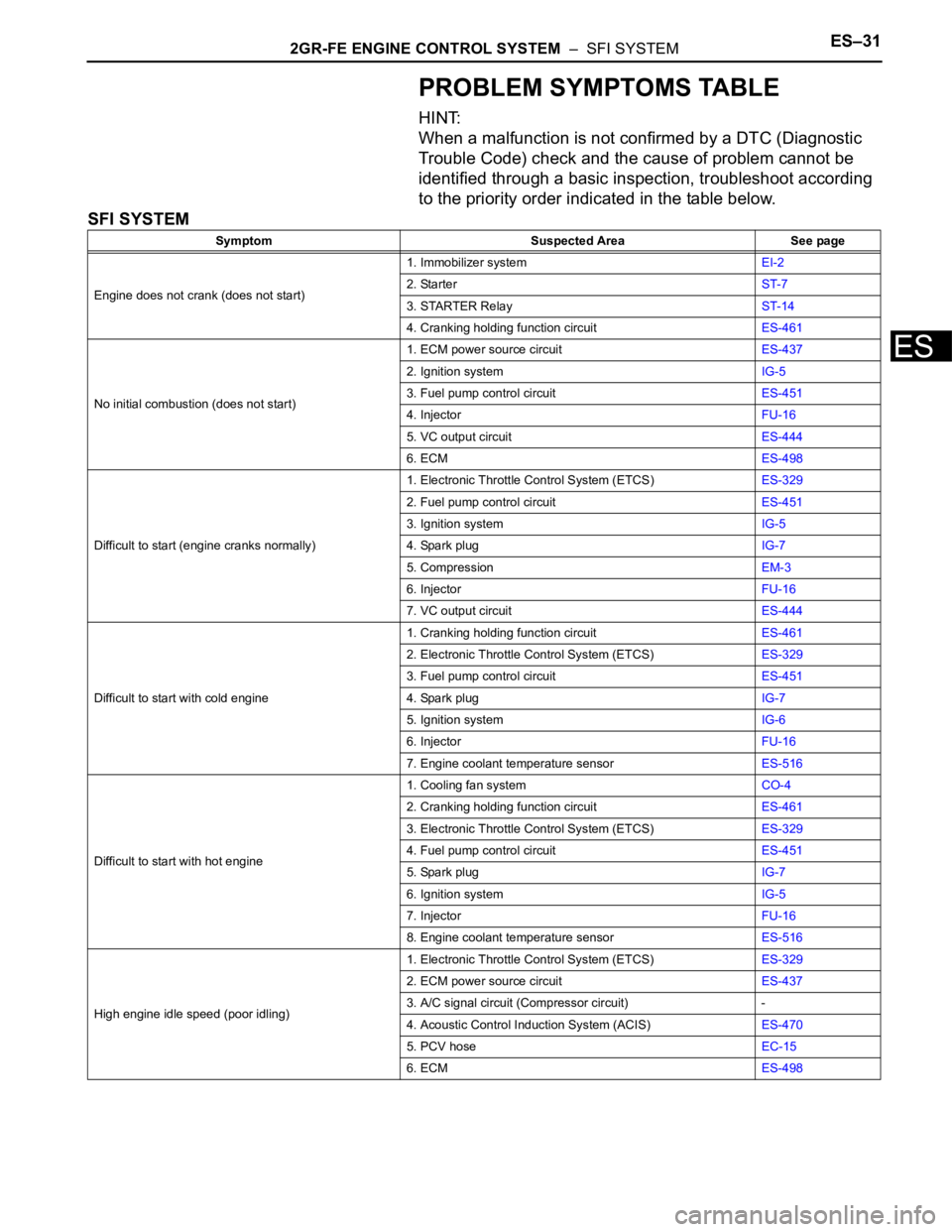
PROBLEM SYMPTOMS TABLE
HINT:
When a malfunction is not confirmed by a DTC (Diagnostic
Trouble Code) check and the cause of problem cannot be
identified through a basic inspection, troubleshoot according
to the priority order indicated in the table below.
SFI SYSTEM
Symptom Suspected Area See page
Engine does not crank (does not start)1. Immobilizer systemEI-2
2. StarterST-7
3. STARTER RelayST-14
4. Cranking holding function circuitES-461
No initial combustion (does not start)1. ECM power source circuitES-437
2. Ignition systemIG-5
3. Fuel pump control circuitES-451
4. InjectorFU-16
5. VC output circuitES-444
6. ECMES-498
Difficult to start (engine cranks normally)1. Electronic Throttle Control System (ETCS)ES-329
2. Fuel pump control circuitES-451
3. Ignition systemIG-5
4. Spark plugIG-7
5. CompressionEM-3
6. InjectorFU-16
7. VC output circuitES-444
Difficult to start with cold engine1. Cranking holding function circuitES-461
2. Electronic Throttle Control System (ETCS)ES-329
3. Fuel pump control circuitES-451
4. Spark plugIG-7
5. Ignition systemIG-6
6. InjectorFU-16
7. Engine coolant temperature sensorES-516
Difficult to start with hot engine1. Cooling fan systemCO-4
2. Cranking holding function circuitES-461
3. Electronic Throttle Control System (ETCS)ES-329
4. Fuel pump control circuitES-451
5. Spark plugIG-7
6. Ignition systemIG-5
7. InjectorFU-16
8. Engine coolant temperature sensorES-516
High engine idle speed (poor idling)1. Electronic Throttle Control System (ETCS)ES-329
2. ECM power source circuitES-437
3. A/C signal circuit (Compressor circuit) -
4. Acoustic Control Induction System (ACIS)ES-470
5. PCV hoseEC-15
6. ECMES-498
Page 810 of 3000
ES–322GR-FE ENGINE CONTROL SYSTEM – SFI SYSTEM
ES
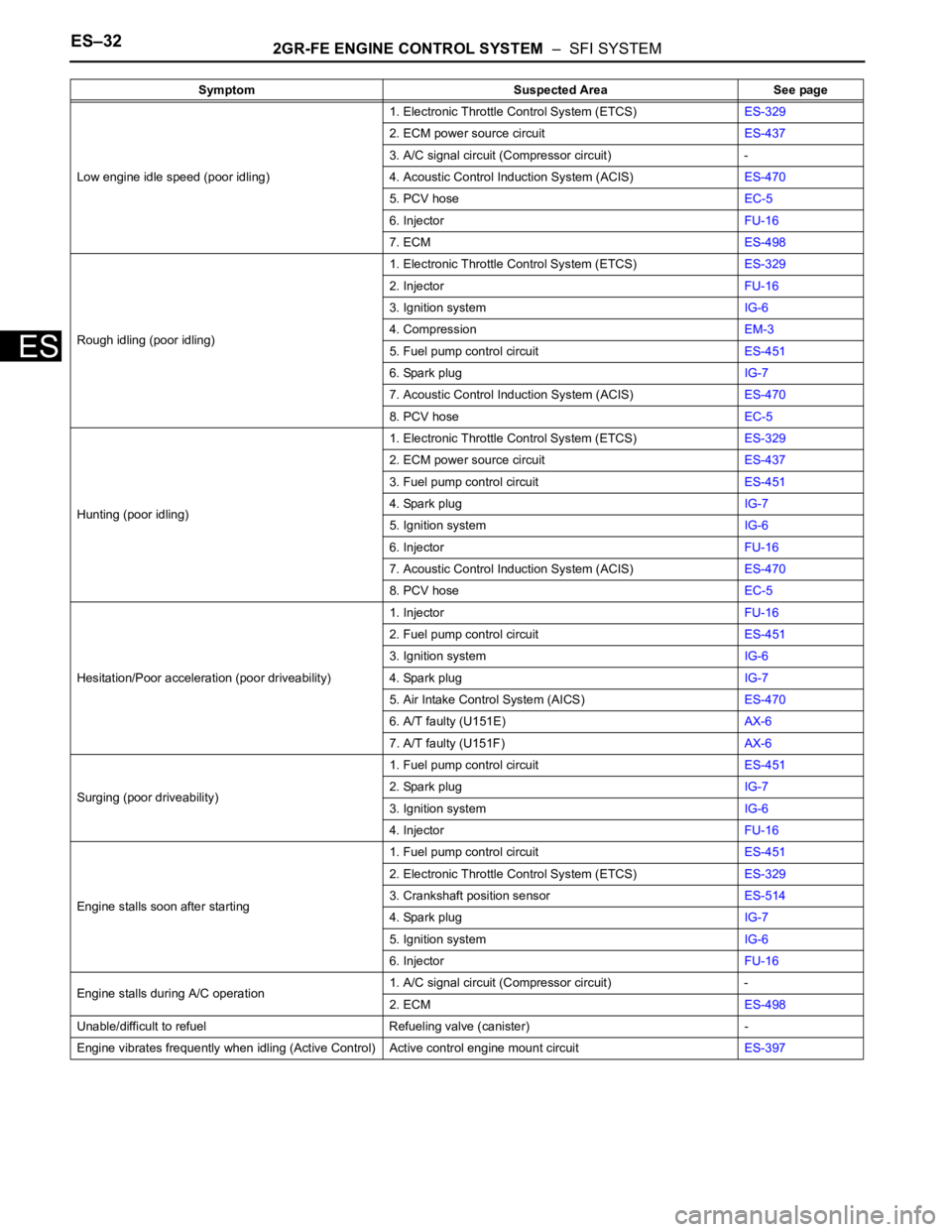
Low engine idle speed (poor idling)1. Electronic Throttle Control System (ETCS)ES-329
2. ECM power source circuitES-437
3. A/C signal circuit (Compressor circuit) -
4. Acoustic Control Induction System (ACIS)ES-470
5. PCV hoseEC-5
6. InjectorFU-16
7. ECMES-498
Rough idling (poor idling)1. Electronic Throttle Control System (ETCS)ES-329
2. InjectorFU-16
3. Ignition systemIG-6
4. CompressionEM-3
5. Fuel pump control circuitES-451
6. Spark plugIG-7
7. Acoustic Control Induction System (ACIS)ES-470
8. PCV hoseEC-5
Hunting (poor idling)1. Electronic Throttle Control System (ETCS)ES-329
2. ECM power source circuitES-437
3. Fuel pump control circuitES-451
4. Spark plugIG-7
5. Ignition systemIG-6
6. InjectorFU-16
7. Acoustic Control Induction System (ACIS)ES-470
8. PCV hoseEC-5
Hesitation/Poor acceleration (poor driveability)1. InjectorFU-16
2. Fuel pump control circuitES-451
3. Ignition systemIG-6
4. Spark plugIG-7
5. Air Intake Control System (AICS)ES-470
6. A/T faulty (U151E)AX-6
7. A/T faulty (U151F)AX-6
Surging (poor driveability)1. Fuel pump control circuitES-451
2. Spark plugIG-7
3. Ignition systemIG-6
4. InjectorFU-16
Engine stalls soon after starting1. Fuel pump control circuitES-451
2. Electronic Throttle Control System (ETCS)ES-329
3. Crankshaft position sensorES-514
4. Spark plugIG-7
5. Ignition systemIG-6
6. InjectorFU-16
Engine stalls during A/C operation1. A/C signal circuit (Compressor circuit) -
2. ECMES-498
Unable/difficult to refuel Refueling valve (canister) -
Engine vibrates frequently when idling (Active Control) Active control engine mount circuitES-397 Symptom Suspected Area See page
Page 863 of 3000
EM–462GR-FE ENGINE MECHANICAL – ENGINE ASSEMBLY
EM
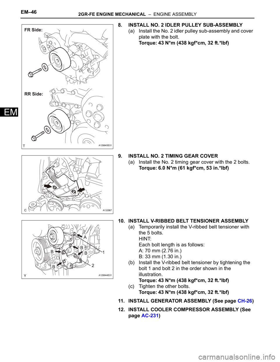
8. INSTALL NO. 2 IDLER PULLEY SUB-ASSEMBLY
(a) Install the No. 2 idler pulley sub-assembly and cover
plate with the bolt.
Torque: 43 N*m (438 kgf*cm, 32 ft.*lbf)
9. INSTALL NO. 2 TIMING GEAR COVER
(a) Install the No. 2 timing gear cover with the 2 bolts.
Torque: 6.0 N*m (61 kgf*cm, 53 in.*lbf)
10. INSTALL V-RIBBED BELT TENSIONER ASSEMBLY
(a) Temporarily install the V-ribbed belt tensioner with
the 5 bolts.
HINT:
Each bolt length is as follows:
A: 70 mm (2.76 in.)
B: 33 mm (1.30 in.)
(b) Install the V-ribbed belt tensioner by tightening the
bolt 1 and bolt 2 in the order shown in the
illustration.
Torque: 43 N*m (438 kgf*cm, 32 ft.*lbf)
(c) Tighten the other bolts.
Torque: 43 N*m (438 kgf*cm, 32 ft.*lbf)
11. INSTALL GENERATOR ASSEMBLY (See page CH-26)
12. INSTALL COOLER COMPRESSOR ASSEMBLY (See
page AC-231)
A129645E01
A132987
A129644E01