2007 TOYOTA SIENNA low idle
[x] Cancel search: low idlePage 1299 of 3000

2GR-FE LUBRICATION – LUBRICATION SYSTEMLU–1
LU
LUBRICATION SYSTEM
ON-VEHICLE INSPECTION
1. CHECK ENGINE OIL LEVEL
(a) Warm up the engine, stop it and wait 5 minutes. The
oil level should be between the dipstick's low level
mark and full level mark.
If the engine oil level is low, check for leakage and
add oil up to the full level mark.
NOTICE:
Do not add engine oil above the full level mark.
2. CHECK ENGINE OIL
(a) Check the engine oil for deterioration, water
contamination, discoloring or thinning.
If the oil is bad, replace the engine oil and engine oil
filter.
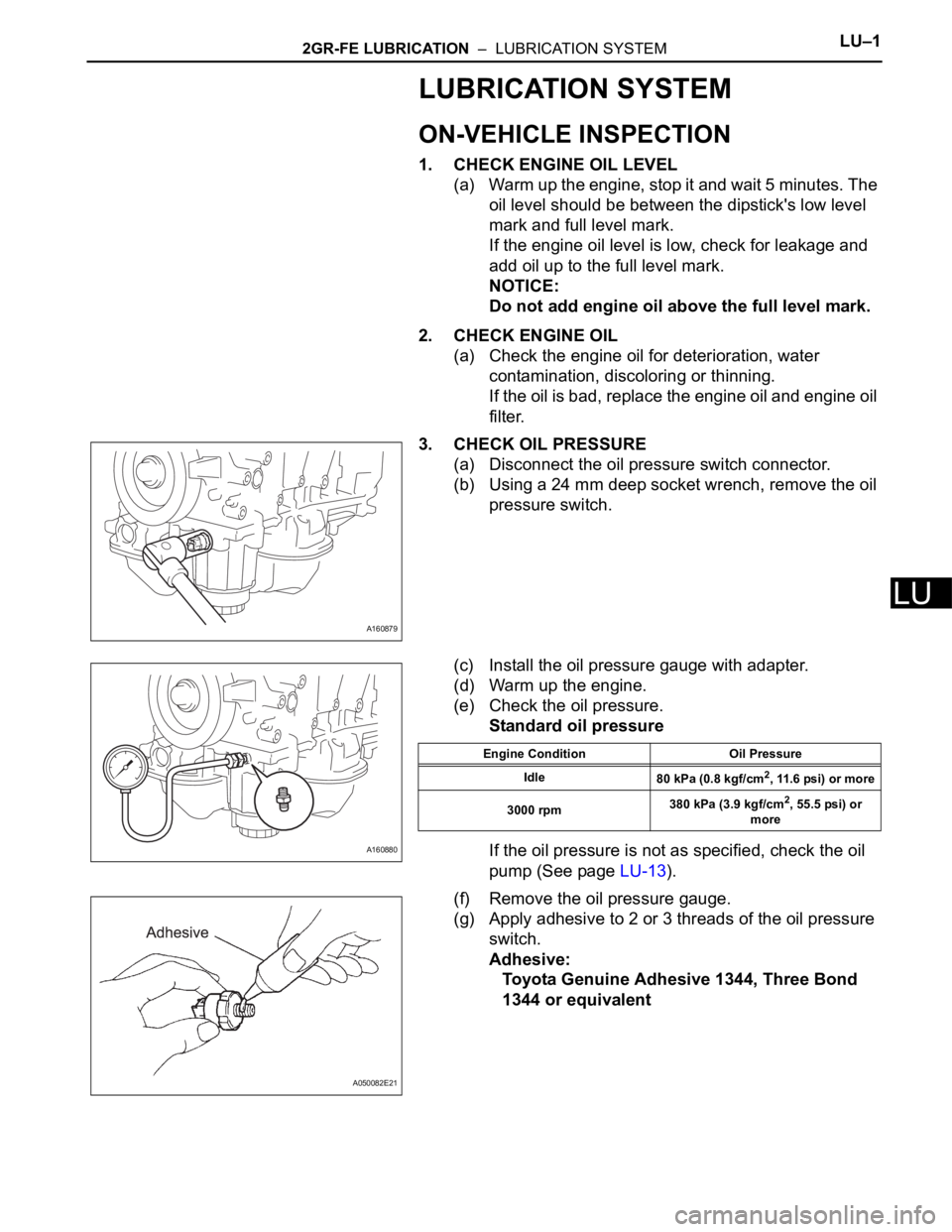
3. CHECK OIL PRESSURE
(a) Disconnect the oil pressure switch connector.
(b) Using a 24 mm deep socket wrench, remove the oil
pressure switch.
(c) Install the oil pressure gauge with adapter.
(d) Warm up the engine.
(e) Check the oil pressure.
Standard oil pressure
If the oil pressure is not as specified, check the oil
pump (See page LU-13).
(f) Remove the oil pressure gauge.
(g) Apply adhesive to 2 or 3 threads of the oil pressure
switch.
Adhesive:
Toyota Genuine Adhesive 1344, Three Bond
1344 or equivalent
A160879
A160880
Engine Condition Oil Pressure
Idle
80 kPa (0.8 kgf/cm
2, 11.6 psi) or more
3000 rpm380 kPa (3.9 kgf/cm
2, 55.5 psi) or
more
A050082E21
Page 1391 of 3000

AX–14U151E AUTOMATIC TRANSAXLE – AUTOMATIC TRANSAXLE SYSTEM
AX
(b) Measure the time lag.
(1) When the shift lever is shifted while the engine is
idling, there will be a certain time lapse or lag
before the shock can be felt. This is used for
checking the condition of the clutch and brake.
NOTICE:
• Perform the test at the normal operating
ATF (Automatic Transmission Fluid)
temperature: 50 to 80
C (122 to 176F).
• Be sure to allow 1 minute interval between
tests.
• Perform the test three times, and measure
the time lags. Calculate the average value
of the three time lags.
• When conducting stall test, do not
continue more than 10 seconds.
(2) Connect the intelligent tester together with the
CAN VIM (controller area network vehicle
interface module) to the DLC3.
(3) Fully apply the parking brake.
(4) Start and warm up the engine and check idle
speed.
Idle speed:
approx. 700 rpm (In N position and A/C
OFF)
(5) Shift the lever from N to D position. Using a stop
watch, measure the time from when the lever is
shifted until the shock is felt.
Time lag:
N
D less than 1.2 seconds
(6) In the same way, measure the time lag for N
R.
Time lag:
N
R less than 1.5 seconds
Evaluation (If N
D or N R time lag is longer than the specified):
Problem Possible cause
N
D time lag is longer• Line pressure is too low
• Forward clutch worn
• No.1 one-way clutch is not operating properly
• U/D (Underdrive) one-way clutch is not operating
• U/D (Underdrive) brake worn
N
R time lag is longer• Line pressure is too low
• Reverse clutch worn
• 1st and reverse brake worn
• U/D (Underdrive) brake worn
Page 1501 of 3000

AX–14U151E AUTOMATIC TRANSAXLE – AUTOMATIC TRANSAXLE SYSTEM
AX
(b) Measure the time lag.
(1) When the shift lever is shifted while the engine is
idling, there will be a certain time lapse or lag
before the shock can be felt. This is used for
checking the condition of the clutch and brake.
NOTICE:
• Perform the test at the normal operating
ATF (Automatic Transmission Fluid)
temperature: 50 to 80
C (122 to 176F).
• Be sure to allow 1 minute interval between
tests.
• Perform the test three times, and measure
the time lags. Calculate the average value
of the three time lags.
• When conducting stall test, do not
continue more than 10 seconds.
(2) Connect the intelligent tester together with the
CAN VIM (controller area network vehicle
interface module) to the DLC3.
(3) Fully apply the parking brake.
(4) Start and warm up the engine and check idle
speed.
Idle speed:
approx. 700 rpm (In N position and A/C
OFF)
(5) Shift the lever from N to D position. Using a stop
watch, measure the time from when the lever is
shifted until the shock is felt.
Time lag:
N
D less than 1.2 seconds
(6) In the same way, measure the time lag for N
R.
Time lag:
N
R less than 1.5 seconds
Evaluation (If N
D or N R time lag is longer than the specified):
Problem Possible cause
N
D time lag is longer• Line pressure is too low
• Forward clutch worn
• No.1 one-way clutch is not operating properly
• U/D (Underdrive) one-way clutch is not operating
• U/D (Underdrive) brake worn
N
R time lag is longer• Line pressure is too low
• Reverse clutch worn
• 1st and reverse brake worn
• U/D (Underdrive) brake worn
Page 1531 of 3000

AX–26U151E AUTOMATIC TRANSAXLE – AUTOMATIC TRANSAXLE SYSTEM
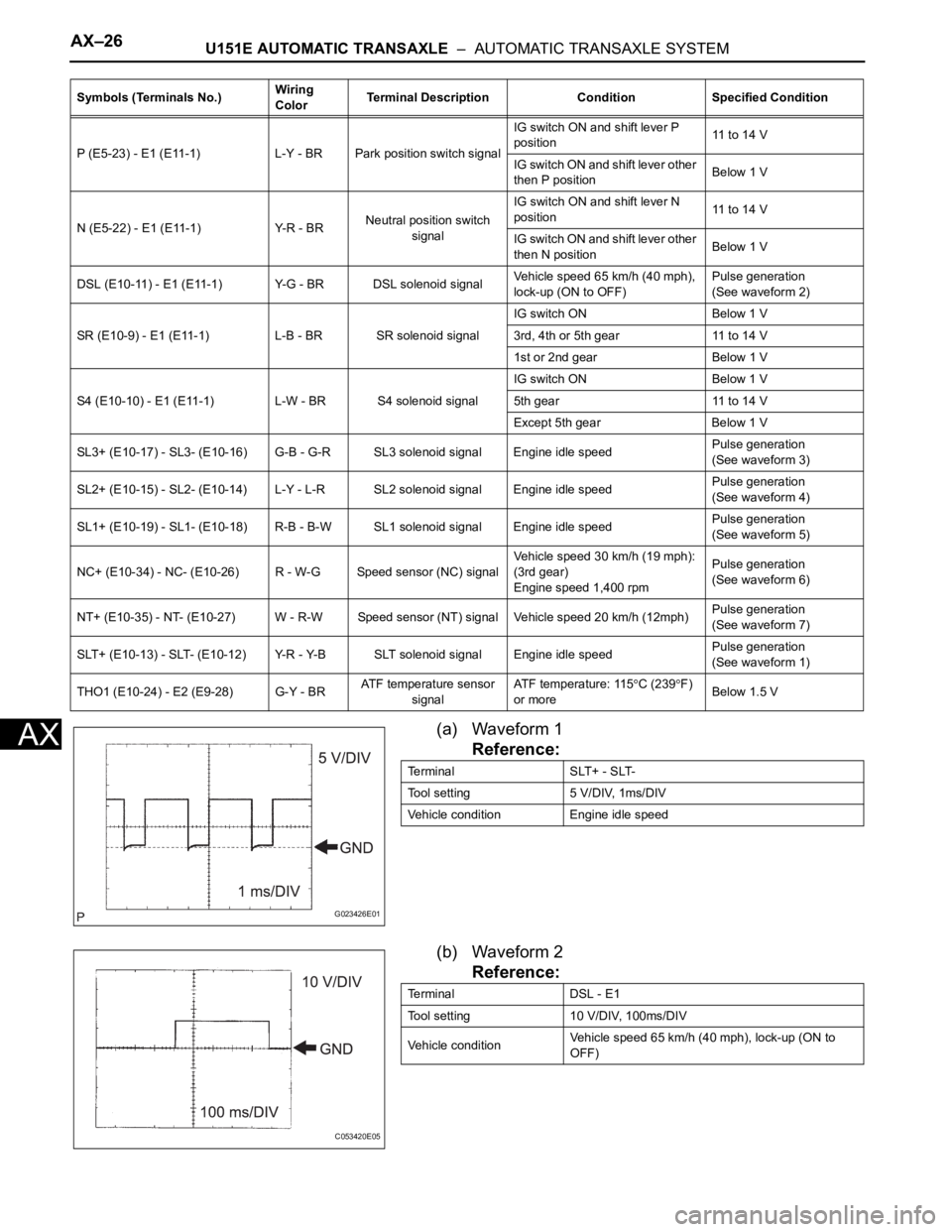
AX(a) Waveform 1
Reference:
(b) Waveform 2
Reference:
P (E5-23) - E1 (E11-1) L-Y - BR Park position switch signalIG switch ON and shift lever P
position11 to 14 V
IG switch ON and shift lever other
then P positionBelow 1 V
N (E5-22) - E1 (E11-1) Y-R - BRNeutral position switch
signalIG switch ON and shift lever N
position11 to 14 V
IG switch ON and shift lever other
then N positionBelow 1 V
DSL (E10-11) - E1 (E11-1) Y-G - BR DSL solenoid signalVehicle speed 65 km/h (40 mph),
lock-up (ON to OFF)Pulse generation
(See waveform 2)
SR (E10-9) - E1 (E11-1) L-B - BR SR solenoid signalIG switch ON Below 1 V
3rd, 4th or 5th gear 11 to 14 V
1st or 2nd gear Below 1 V
S4 (E10-10) - E1 (E11-1) L-W - BR S4 solenoid signalIG switch ON Below 1 V
5th gear 11 to 14 V
Except 5th gear Below 1 V
SL3+ (E10-17) - SL3- (E10-16) G-B - G-R SL3 solenoid signal Engine idle speedPulse generation
(See waveform 3)
SL2+ (E10-15) - SL2- (E10-14) L-Y - L-R SL2 solenoid signal Engine idle speedPulse generation
(See waveform 4)
SL1+ (E10-19) - SL1- (E10-18) R-B - B-W SL1 solenoid signal Engine idle speedPulse generation
(See waveform 5)
NC+ (E10-34) - NC- (E10-26) R - W-G Speed sensor (NC) signalVehicle speed 30 km/h (19 mph):
(3rd gear)
Engine speed 1,400 rpmPulse generation
(See waveform 6)
NT+ (E10-35) - NT- (E10-27) W - R-W Speed sensor (NT) signal Vehicle speed 20 km/h (12mph)Pulse generation
(See waveform 7)
SLT+ (E10-13) - SLT- (E10-12) Y-R - Y-B SLT solenoid signal Engine idle speedPulse generation
(See waveform 1)
THO1 (E10-24) - E2 (E9-28) G-Y - BRATF temperature sensor
signalATF temperature: 115
C (239F)
or moreBelow 1.5 V Symbols (Terminals No.)Wiring
ColorTerminal Description Condition Specified Condition
G023426E01
Terminal SLT+ - SLT-
Tool setting 5 V/DIV, 1ms/DIV
Vehicle condition Engine idle speed
C053420E05
Terminal DSL - E1
Tool setting 10 V/DIV, 100ms/DIV
Vehicle conditionVehicle speed 65 km/h (40 mph), lock-up (ON to
OFF)
Page 1697 of 3000

AX–14U151F AUTOMATIC TRANSAXLE – AUTOMATIC TRANSAXLE SYSTEM
AX
(b) Measure the time lag.
(1) When the shift lever is shifted while the engine is
idling, there will be a certain time lapse or lag
before the shock can be felt. This is used for
checking the condition of the clutch and brake.
NOTICE:
• Perform the test at the normal operating
ATF (Automatic Transmission Fluid)
temperature: 50 to 80
C (122 to 176F).
• Be sure to allow 1 minute interval between
tests.
• Perform the test three times, and measure
the time lags. Calculate the average value
of the three time lags.
• When conducting stall test, do not
continue more than 10 seconds.
(2) Connect the intelligent tester together with the
CAN VIM (controller area network vehicle
interface module) to the DLC3.
(3) Fully apply the parking brake.
(4) Start and warm up the engine and check idle
speed.
Idle speed:
approx. 700 rpm (In N position and A/C
OFF)
(5) Shift the lever from N to D position. Using a stop
watch, measure the time from when the lever is
shifted until the shock is felt.
Time lag:
N
D less than 1.2 seconds
(6) In the same way, measure the time lag for N
R.
Time lag:
N
R less than 1.5 seconds
Evaluation (If N
D or N R time lag is longer than the specified):
Problem Possible cause
N
D time lag is longer• Line pressure is too low
• Forward clutch worn
• No.1 one-way clutch is not operating properly
• U/D (Underdrive) one-way clutch is not operating
• U/D (Underdrive) brake worn
N
R time lag is longer• Line pressure is too low
• Reverse clutch worn
• 1st and reverse brake worn
• U/D (Underdrive) brake worn
Page 1807 of 3000

AX–14U151F AUTOMATIC TRANSAXLE – AUTOMATIC TRANSAXLE SYSTEM
AX
(b) Measure the time lag.
(1) When the shift lever is shifted while the engine is
idling, there will be a certain time lapse or lag
before the shock can be felt. This is used for
checking the condition of the clutch and brake.
NOTICE:
• Perform the test at the normal operating
ATF (Automatic Transmission Fluid)
temperature: 50 to 80
C (122 to 176F).
• Be sure to allow 1 minute interval between
tests.
• Perform the test three times, and measure
the time lags. Calculate the average value
of the three time lags.
• When conducting stall test, do not
continue more than 10 seconds.
(2) Connect the intelligent tester together with the
CAN VIM (controller area network vehicle
interface module) to the DLC3.
(3) Fully apply the parking brake.
(4) Start and warm up the engine and check idle
speed.
Idle speed:
approx. 700 rpm (In N position and A/C
OFF)
(5) Shift the lever from N to D position. Using a stop
watch, measure the time from when the lever is
shifted until the shock is felt.
Time lag:
N
D less than 1.2 seconds
(6) In the same way, measure the time lag for N
R.
Time lag:
N
R less than 1.5 seconds
Evaluation (If N
D or N R time lag is longer than the specified):
Problem Possible cause
N
D time lag is longer• Line pressure is too low
• Forward clutch worn
• No.1 one-way clutch is not operating properly
• U/D (Underdrive) one-way clutch is not operating
• U/D (Underdrive) brake worn
N
R time lag is longer• Line pressure is too low
• Reverse clutch worn
• 1st and reverse brake worn
• U/D (Underdrive) brake worn
Page 1834 of 3000

AX–26U151F AUTOMATIC TRANSAXLE – AUTOMATIC TRANSAXLE SYSTEM
AX
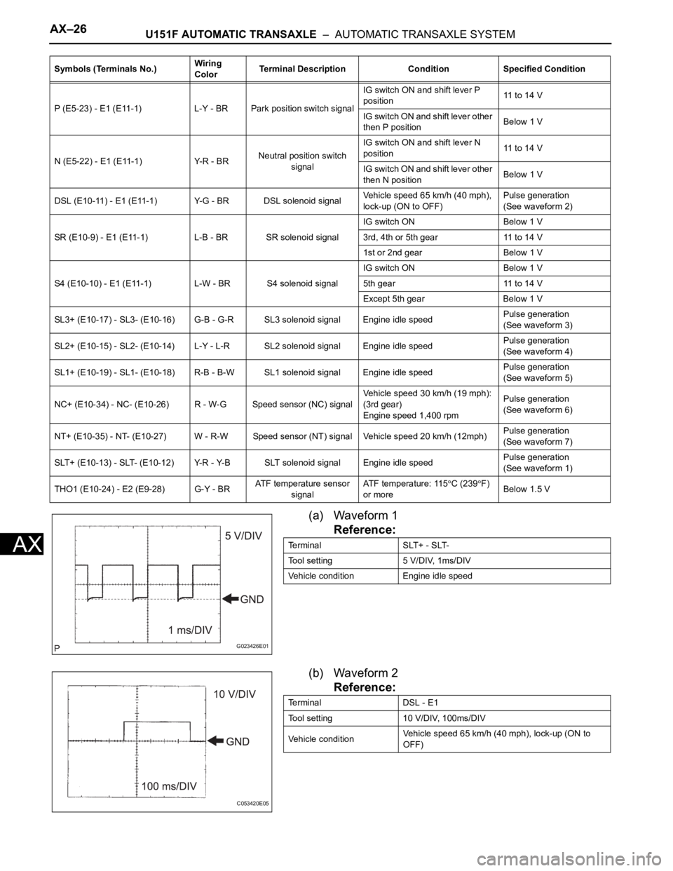
(a) Waveform 1
Reference:
(b) Waveform 2
Reference:
P (E5-23) - E1 (E11-1) L-Y - BR Park position switch signalIG switch ON and shift lever P
position11 to 14 V
IG switch ON and shift lever other
then P positionBelow 1 V
N (E5-22) - E1 (E11-1) Y-R - BRNeutral position switch
signalIG switch ON and shift lever N
position11 to 14 V
IG switch ON and shift lever other
then N positionBelow 1 V
DSL (E10-11) - E1 (E11-1) Y-G - BR DSL solenoid signalVehicle speed 65 km/h (40 mph),
lock-up (ON to OFF)Pulse generation
(See waveform 2)
SR (E10-9) - E1 (E11-1) L-B - BR SR solenoid signalIG switch ON Below 1 V
3rd, 4th or 5th gear 11 to 14 V
1st or 2nd gear Below 1 V
S4 (E10-10) - E1 (E11-1) L-W - BR S4 solenoid signalIG switch ON Below 1 V
5th gear 11 to 14 V
Except 5th gear Below 1 V
SL3+ (E10-17) - SL3- (E10-16) G-B - G-R SL3 solenoid signal Engine idle speedPulse generation
(See waveform 3)
SL2+ (E10-15) - SL2- (E10-14) L-Y - L-R SL2 solenoid signal Engine idle speedPulse generation
(See waveform 4)
SL1+ (E10-19) - SL1- (E10-18) R-B - B-W SL1 solenoid signal Engine idle speedPulse generation
(See waveform 5)
NC+ (E10-34) - NC- (E10-26) R - W-G Speed sensor (NC) signalVehicle speed 30 km/h (19 mph):
(3rd gear)
Engine speed 1,400 rpmPulse generation
(See waveform 6)
NT+ (E10-35) - NT- (E10-27) W - R-W Speed sensor (NT) signal Vehicle speed 20 km/h (12mph)Pulse generation
(See waveform 7)
SLT+ (E10-13) - SLT- (E10-12) Y-R - Y-B SLT solenoid signal Engine idle speedPulse generation
(See waveform 1)
THO1 (E10-24) - E2 (E9-28) G-Y - BRATF temperature sensor
signalATF temperature: 115
C (239F)
or moreBelow 1.5 V Symbols (Terminals No.)Wiring
ColorTerminal Description Condition Specified Condition
G023426E01
Terminal SLT+ - SLT-
Tool setting 5 V/DIV, 1ms/DIV
Vehicle condition Engine idle speed
C053420E05
Terminal DSL - E1
Tool setting 10 V/DIV, 100ms/DIV
Vehicle conditionVehicle speed 65 km/h (40 mph), lock-up (ON to
OFF)
Page 2449 of 3000

BRAKE CONTROL – VEHICLE STABILITY CONTROL SYSTEMBC–87
BC
DATA LIST / ACTIVE TEST
1. DATA LIST
HINT:
With the intelligent tester connected to the DLC3 and the
ignition switch to the ON position, the ABS, TRAC and
VSC data list can be displayed. Follow the prompts on
the tester screen to access the DATA LIST.
Tester Display Measurement Item/Range Normal Condition Diagnostic Note
ABS MOT RELAY ABS motor relay / ON or OFF ON : Motor relay ON -
SOL RELAY Solenoid relay / ON or OFF ON : Solenoid relay ON -
VSC / TRC OFF SW* Traction OFF switch / ON or OFF ON : Traction OFF switch OFF -
IDLE SW Main idle switch / ON or OFFON : Accelerator pedal released
OFF : Accelerator pedal
depressed-
STOP LIGHT SW Stop light switch / ON or OFFON : Brake pedal depressed
OFF : Brake pedal released-
PKB SW Parking brake switch / ON or OFFON : Parking brake applied
OFF : Parking brake released-
ABS OPERT FRABS operation (FR) / BEFORE or
OPERATEBEFORE : No ABS operation
(FR)
OPERATE : During ABS
operation (FR)-
ABS OPERT FLABS operation (FL) / BEFORE or
OPERATEBEFORE : No ABS operation (FL)
OPERATE : During ABS
operation (FL)-
ABS OPERT RRABS operation (RR) / BEFORE or
OPERATEBEFORE : No ABS operation
(RR)
OPERATE : During ABS
operation (RR)-
ABS OPERT RLABS operation (RL) / BEFORE or
OPERATEBEFORE : No ABS operation
(RL)
OPERATE : During ABS
operation (RL)-
WHEEL SPD FR Wheel speed sensor (FR)
reading / min.: 0 km/h (0 MPH,
max.: 326 km/h (202 MPH)Actual wheel speed Similar speed as indicated on
speed meter
WHEEL SPD FL Wheel speed sensor (FL)
reading / min.: 0 km/h (0 MPH,
max.: 326 km/h (202 MPH)Actual wheel speedSimilar speed as indicated on
speed meter
WHEEL SPD RR Wheel speed sensor (RR)
reading / min.: 0 km/h (0 MPH,
max.: 326 km/h (202 MPH) Actual wheel speedSimilar speed as indicated on
speed meter
WHEEL SPD RL Wheel speed sensor (RL)
reading / min.: 0 km/h (0 MPH,
max.: 326 km/h (202 MPH) Actual wheel speedSimilar speed as indicated on
speed meter
DECELERAT SENSDeceleration sensor 1 reading /
min.: -1.869 G, max.: 1.869 GApproximately 0 +- 0.13G at still
conditionReading changes when vehicle is
bounced
DECELERAT SENS2Deceleration sensor 2 reading /
min.: -1.869 G, max.: 1.869 GApproximately 0 +- 0.13G at still
conditionReading changes when vehicle is
bounced
IG VOLTAGEECU power supply voltage /
UNDER / NORMALNORMAL: 9.5 V or over UNDER:
Below 9.5 V-
SFRRABS solenoid (SFRR) / ON or
OFFON : Operate -
SFRHABS solenoid (SFRH) / ON or
OFF
ON : Operate -
SFLRABS solenoid (SFLR) / ON or
OFFON : Operate -
SFLHABS solenoid (SFLH) / ON or
OFFON : Operate -