2007 TOYOTA SIENNA fuel type
[x] Cancel search: fuel typePage 353 of 3000
2GR-FE ENGINE CONTROL SYSTEM – SFI SYSTEMES–27
ES
Contents:
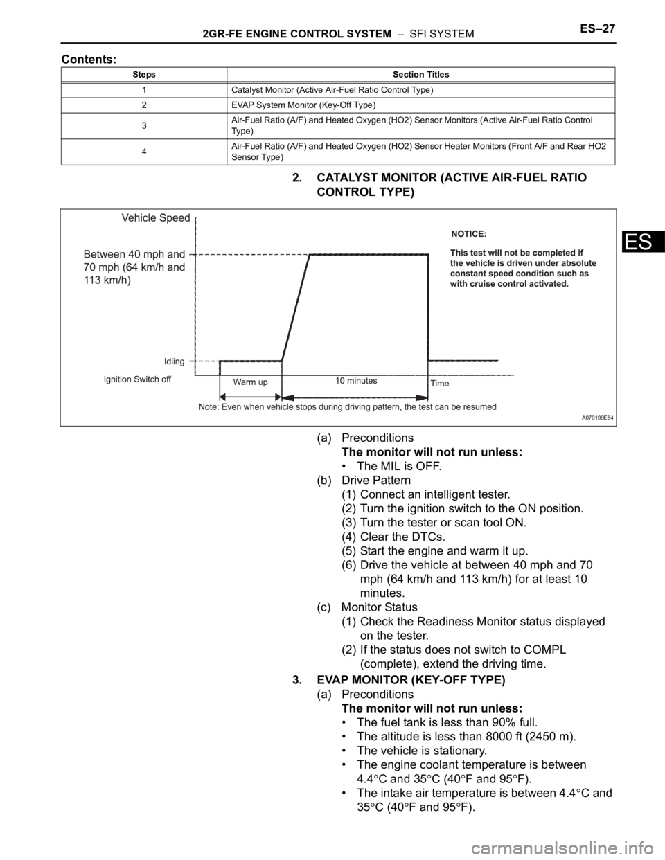
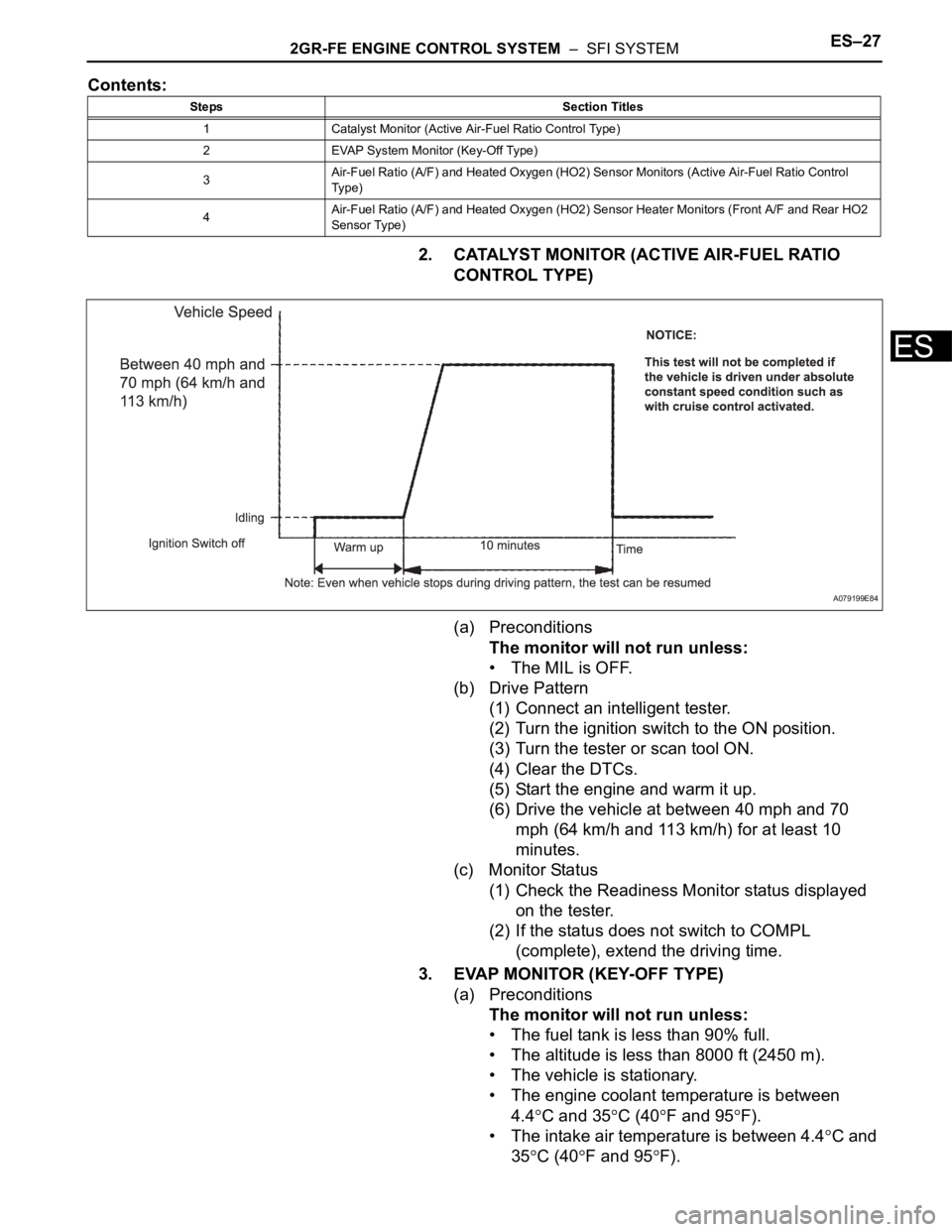
2. CATALYST MONITOR (ACTIVE AIR-FUEL RATIO
CONTROL TYPE)
(a) Preconditions
The monitor will not run unless:
• The MIL is OFF.
(b) Drive Pattern
(1) Connect an intelligent tester.
(2) Turn the ignition switch to the ON position.
(3) Turn the tester or scan tool ON.
(4) Clear the DTCs.
(5) Start the engine and warm it up.
(6) Drive the vehicle at between 40 mph and 70
mph (64 km/h and 113 km/h) for at least 10
minutes.
(c) Monitor Status
(1) Check the Readiness Monitor status displayed
on the tester.
(2) If the status does not switch to COMPL
(complete), extend the driving time.
3. EVAP MONITOR (KEY-OFF TYPE)
(a) Preconditions
The monitor will not run unless:
• The fuel tank is less than 90% full.
• The altitude is less than 8000 ft (2450 m).
• The vehicle is stationary.
• The engine coolant temperature is between
4.4
C and 35C (40F and 95F).
• The intake air temperature is between 4.4
C and
35
C (40F and 95F).
Steps Section Titles
1 Catalyst Monitor (Active Air-Fuel Ratio Control Type)
2 EVAP System Monitor (Key-Off Type)
3Air-Fuel Ratio (A/F) and Heated Oxygen (HO2) Sensor Monitors (Active Air-Fuel Ratio Control
Ty p e )
4Air-Fuel Ratio (A/F) and Heated Oxygen (HO2) Sensor Heater Monitors (Front A/F and Rear HO2
Sensor Type)
A079199E84
Page 355 of 3000
2GR-FE ENGINE CONTROL SYSTEM – SFI SYSTEMES–29
ES
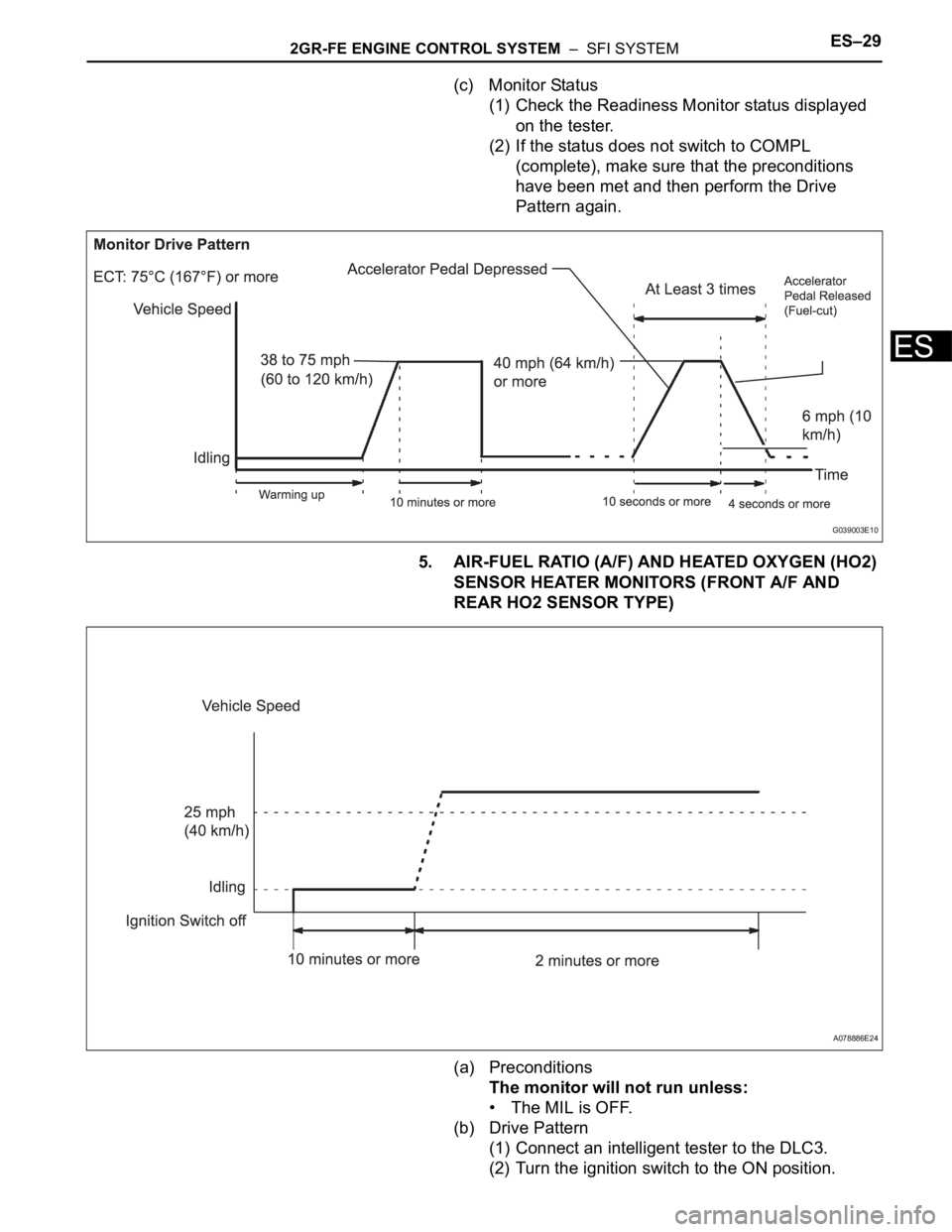
(c) Monitor Status
(1) Check the Readiness Monitor status displayed
on the tester.
(2) If the status does not switch to COMPL
(complete), make sure that the preconditions
have been met and then perform the Drive
Pattern again.
5. AIR-FUEL RATIO (A/F) AND HEATED OXYGEN (HO2)
SENSOR HEATER MONITORS (FRONT A/F AND
REAR HO2 SENSOR TYPE)
(a) Preconditions
The monitor will not run unless:
• The MIL is OFF.
(b) Drive Pattern
(1) Connect an intelligent tester to the DLC3.
(2) Turn the ignition switch to the ON position.
G039003E10
A078886E24
Page 459 of 3000

2GR-FE ENGINE CONTROL SYSTEM – SFI SYSTEMES–153
ES
HINT:
These DTCs relate to the Throttle Position (TP) sensor.
DESCRIPTION
HINT:
This ETC (Electrical Throttle Control System) does not use a throttle cable.
The Throttle Position (TP) sensor is mounted on the throttle body, and detects the opening angle of the
throttle valve. This sensor is a non-contact type, and uses Hall-effect elements, in order to yield accurate
signals, even in extreme driving conditions, such as at high speeds as well as very low speeds.
The TP sensor has two sensor circuits which each transmits a signal, VTA1 and VTA2. VTA1 is used to
detect the throttle valve angle and VTA2 is used to detect malfunctions in VTA1. The sensor signal
voltages vary between 0 V and 5 V in proportion to the throttle valve opening angle, and are transmitted to
the VTA terminals of the ECM.
As the valve closes, the sensor output voltage decreases and as the valve opens, the sensor output
voltage increases. The ECM calculates the throttle valve opening angle according to these signals and
controls the throttle actuator in response to driver inputs. These signals are also used in calculations such
as air-fuel ratio correction, power increase correction and fuel-cut control.
DTC P0120Throttle / Pedal Position Sensor / Switch "A"
Circuit
DTC P0122Throttle / Pedal Position Sensor / Switch "A"
Circuit Low Input
DTC P0123Throttle / Pedal Position Sensor / Switch "A"
Circuit High Input
DTC P0220Throttle / Pedal Position Sensor / Switch "B"
Circuit
DTC P0222Throttle / Pedal Position Sensor / Switch "B"
Circuit Low Input
DTC P0223Throttle / Pedal Position Sensor / Switch "B"
Circuit High Input
DTC P2135Throttle / Pedal Position Sensor / Switch "A" /
"B" Voltage Correlation
Page 656 of 3000
2GR-FE ENGINE CONTROL SYSTEM – SFI SYSTEMES–363
ES
HINT:
• Although the DTC titles say oxygen sensor, these DTCs relate to the Air-Fuel Ratio (A/F) sensor.
• Sensor 1 refers to the sensor mounted in front of the Three-Way Catalytic Converter (TWC) and
located near the engine assembly.
DESCRIPTION
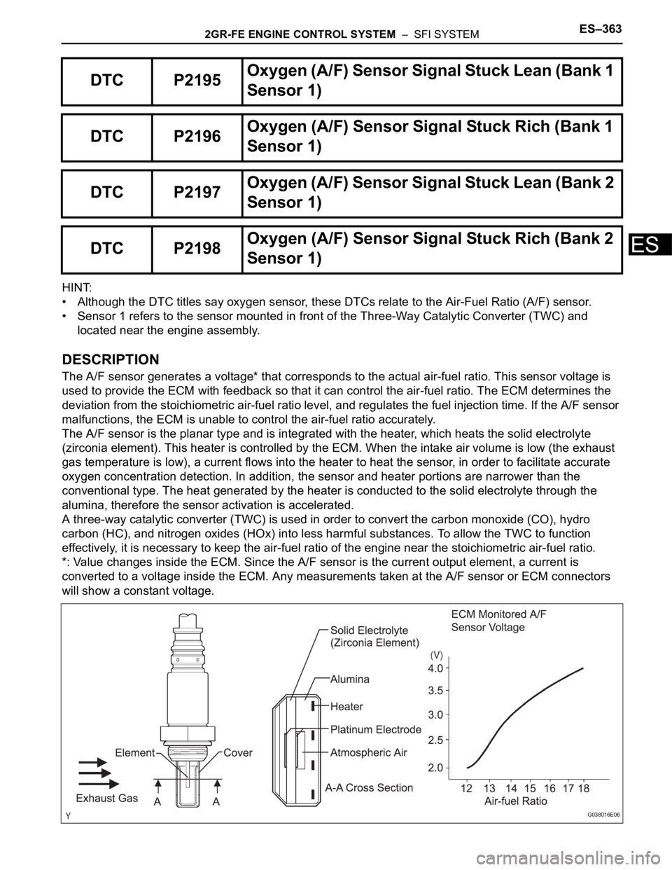
The A/F sensor generates a voltage* that corresponds to the actual air-fuel ratio. This sensor voltage is
used to provide the ECM with feedback so that it can control the air-fuel ratio. The ECM determines the
deviation from the stoichiometric air-fuel ratio level, and regulates the fuel injection time. If the A/F sensor
malfunctions, the ECM is unable to control the air-fuel ratio accurately.
The A/F sensor is the planar type and is integrated with the heater, which heats the solid electrolyte
(zirconia element). This heater is controlled by the ECM. When the intake air volume is low (the exhaust
gas temperature is low), a current flows into the heater to heat the sensor, in order to facilitate accurate
oxygen concentration detection. In addition, the sensor and heater portions are narrower than the
conventional type. The heat generated by the heater is conducted to the solid electrolyte through the
alumina, therefore the sensor activation is accelerated.
A three-way catalytic converter (TWC) is used in order to convert the carbon monoxide (CO), hydro
carbon (HC), and nitrogen oxides (HOx) into less harmful substances. To allow the TWC to function
effectively, it is necessary to keep the air-fuel ratio of the engine near the stoichiometric air-fuel ratio.
*: Value changes inside the ECM. Since the A/F sensor is the current output element, a current is
converted to a voltage inside the ECM. Any measurements taken at the A/F sensor or ECM connectors
will show a constant voltage.
DTC P2195Oxyg en ( A/ F) S en so r S ig n al Stu ck Lea n (Ban k 1
Sensor 1)
DTC P2196Oxygen (A/F) Sensor Signal Stuck Rich (Bank 1
Sensor 1)
DTC P2197Oxyg en ( A/ F) S en so r S ig n al Stu ck Lea n (Ban k 2
Sensor 1)
DTC P2198Oxygen (A/F) Sensor Signal Stuck Rich (Bank 2
Sensor 1)
G038016E06
Page 803 of 3000
2GR-FE ENGINE CONTROL SYSTEM – SFI SYSTEMES–27
ES
Contents:
2. CATALYST MONITOR (ACTIVE AIR-FUEL RATIO
CONTROL TYPE)
(a) Preconditions
The monitor will not run unless:
• The MIL is OFF.
(b) Drive Pattern
(1) Connect an intelligent tester.
(2) Turn the ignition switch to the ON position.
(3) Turn the tester or scan tool ON.
(4) Clear the DTCs.
(5) Start the engine and warm it up.
(6) Drive the vehicle at between 40 mph and 70
mph (64 km/h and 113 km/h) for at least 10
minutes.
(c) Monitor Status
(1) Check the Readiness Monitor status displayed
on the tester.
(2) If the status does not switch to COMPL
(complete), extend the driving time.
3. EVAP MONITOR (KEY-OFF TYPE)
(a) Preconditions
The monitor will not run unless:
• The fuel tank is less than 90% full.
• The altitude is less than 8000 ft (2450 m).
• The vehicle is stationary.
• The engine coolant temperature is between
4.4
C and 35C (40F and 95F).
• The intake air temperature is between 4.4
C and
35
C (40F and 95F).
Steps Section Titles
1 Catalyst Monitor (Active Air-Fuel Ratio Control Type)
2 EVAP System Monitor (Key-Off Type)
3Air-Fuel Ratio (A/F) and Heated Oxygen (HO2) Sensor Monitors (Active Air-Fuel Ratio Control
Ty p e )
4Air-Fuel Ratio (A/F) and Heated Oxygen (HO2) Sensor Heater Monitors (Front A/F and Rear HO2
Sensor Type)
A079199E84
Page 805 of 3000
2GR-FE ENGINE CONTROL SYSTEM – SFI SYSTEMES–29
ES
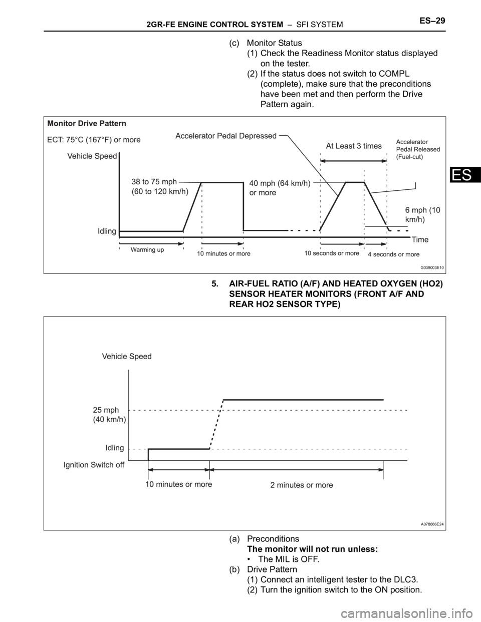
(c) Monitor Status
(1) Check the Readiness Monitor status displayed
on the tester.
(2) If the status does not switch to COMPL
(complete), make sure that the preconditions
have been met and then perform the Drive
Pattern again.
5. AIR-FUEL RATIO (A/F) AND HEATED OXYGEN (HO2)
SENSOR HEATER MONITORS (FRONT A/F AND
REAR HO2 SENSOR TYPE)
(a) Preconditions
The monitor will not run unless:
• The MIL is OFF.
(b) Drive Pattern
(1) Connect an intelligent tester to the DLC3.
(2) Turn the ignition switch to the ON position.
G039003E10
A078886E24
Page 1123 of 3000
FU–22GR-FE FUEL – FUEL SYSTEM
FU
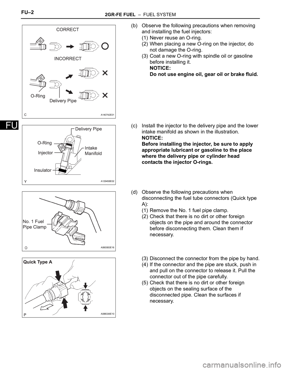
(b) Observe the following precautions when removing
and installing the fuel injectors:
(1) Never reuse an O-ring.
(2) When placing a new O-ring on the injector, do
not damage the O-ring.
(3) Coat a new O-ring with spindle oil or gasoline
before installing it.
NOTICE:
Do not use engine oil, gear oil or brake fluid.
(c) Install the injector to the delivery pipe and the lower
intake manifold as shown in the illustration.
NOTICE:
Before installing the injector, be sure to apply
appropriate lubricant or gasoline to the place
where the delivery pipe or cylinder head
contacts the injector O-rings.
(d) Observe the following precautions when
disconnecting the fuel tube connectors (Quick type
A):
(1) Remove the No. 1 fuel pipe clamp.
(2) Check that there is no dirt or other foreign
objects on the pipe and around the connector
before disconnecting them. Clean them if
necessary.
(3) Disconnect the connector from the pipe by hand.
(4) If the connector and the pipe are stuck, push in
and pull on the connector to release it. Pull the
connector out of the pipe carefully.
(5) Check that there is no dirt or other foreign
objects on the sealing surface of the
disconnected pipe. Clean the surfaces if
necessary.
A140742E01
A129458E02
A060083E16
A088336E10
Page 1124 of 3000
2GR-FE FUEL – FUEL SYSTEMFU–3
FU
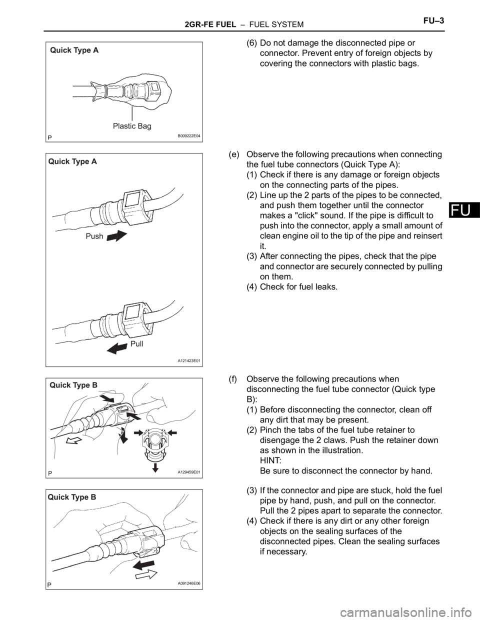
(6) Do not damage the disconnected pipe or
connector. Prevent entry of foreign objects by
covering the connectors with plastic bags.
(e) Observe the following precautions when connecting
the fuel tube connectors (Quick Type A):
(1) Check if there is any damage or foreign objects
on the connecting parts of the pipes.
(2) Line up the 2 parts of the pipes to be connected,
and push them together until the connector
makes a "click" sound. If the pipe is difficult to
push into the connector, apply a small amount of
clean engine oil to the tip of the pipe and reinsert
it.
(3) After connecting the pipes, check that the pipe
and connector are securely connected by pulling
on them.
(4) Check for fuel leaks.
(f) Observe the following precautions when
disconnecting the fuel tube connector (Quick type
B):
(1) Before disconnecting the connector, clean off
any dirt that may be present.
(2) Pinch the tabs of the fuel tube retainer to
disengage the 2 claws. Push the retainer down
as shown in the illustration.
HINT:
Be sure to disconnect the connector by hand.
(3) If the connector and pipe are stuck, hold the fuel
pipe by hand, push, and pull on the connector.
Pull the 2 pipes apart to separate the connector.
(4) Check if there is any dirt or any other foreign
objects on the sealing surfaces of the
disconnected pipes. Clean the sealing surfaces
if necessary.
B009222E04
A121423E01
A129459E01
A091246E06