2007 TOYOTA SIENNA display
[x] Cancel search: displayPage 52 of 3000
IN–40INTRODUCTION – HOW TO TROUBLESHOOT ECU CONTROLLED SYSTEMS
IN
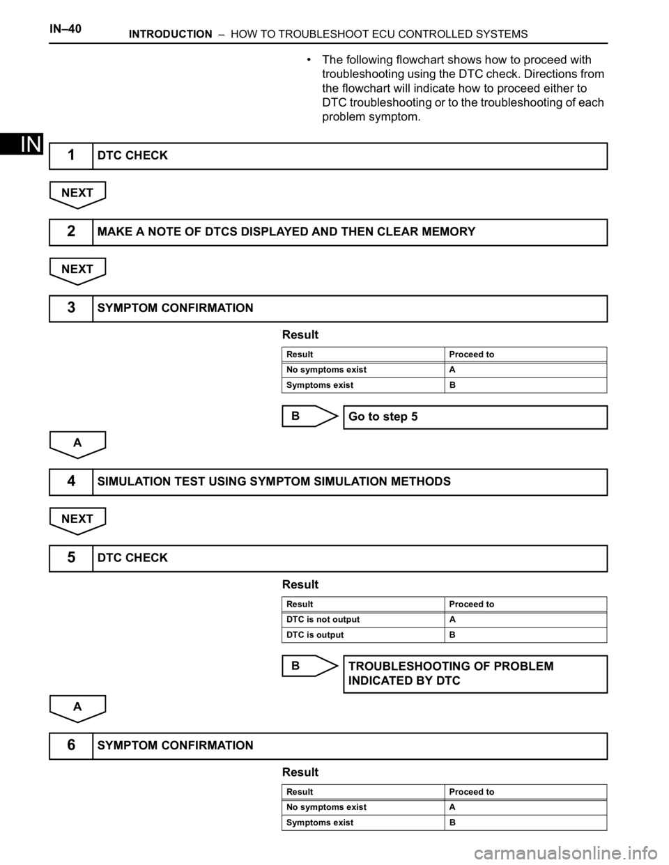
• The following flowchart shows how to proceed with
troubleshooting using the DTC check. Directions from
the flowchart will indicate how to proceed either to
DTC troubleshooting or to the troubleshooting of each
problem symptom.
NEXT
NEXT
Result
B
A
NEXT
Result
B
A
Result
1DTC CHECK
2MAKE A NOTE OF DTCS DISPLAYED AND THEN CLEAR MEMORY
3SYMPTOM CONFIRMATION
Result Proceed to
No symptoms exist A
Symptoms exist B
Go to step 5
4SIMULATION TEST USING SYMPTOM SIMULATION METHODS
5DTC CHECK
Result Proceed to
DTC is not output A
DTC is output B
TROUBLESHOOTING OF PROBLEM
INDICATED BY DTC
6SYMPTOM CONFIRMATION
Result Proceed to
No symptoms exist A
Symptoms exist B
Page 53 of 3000
INTRODUCTION – HOW TO TROUBLESHOOT ECU CONTROLLED SYSTEMSIN–41
IN
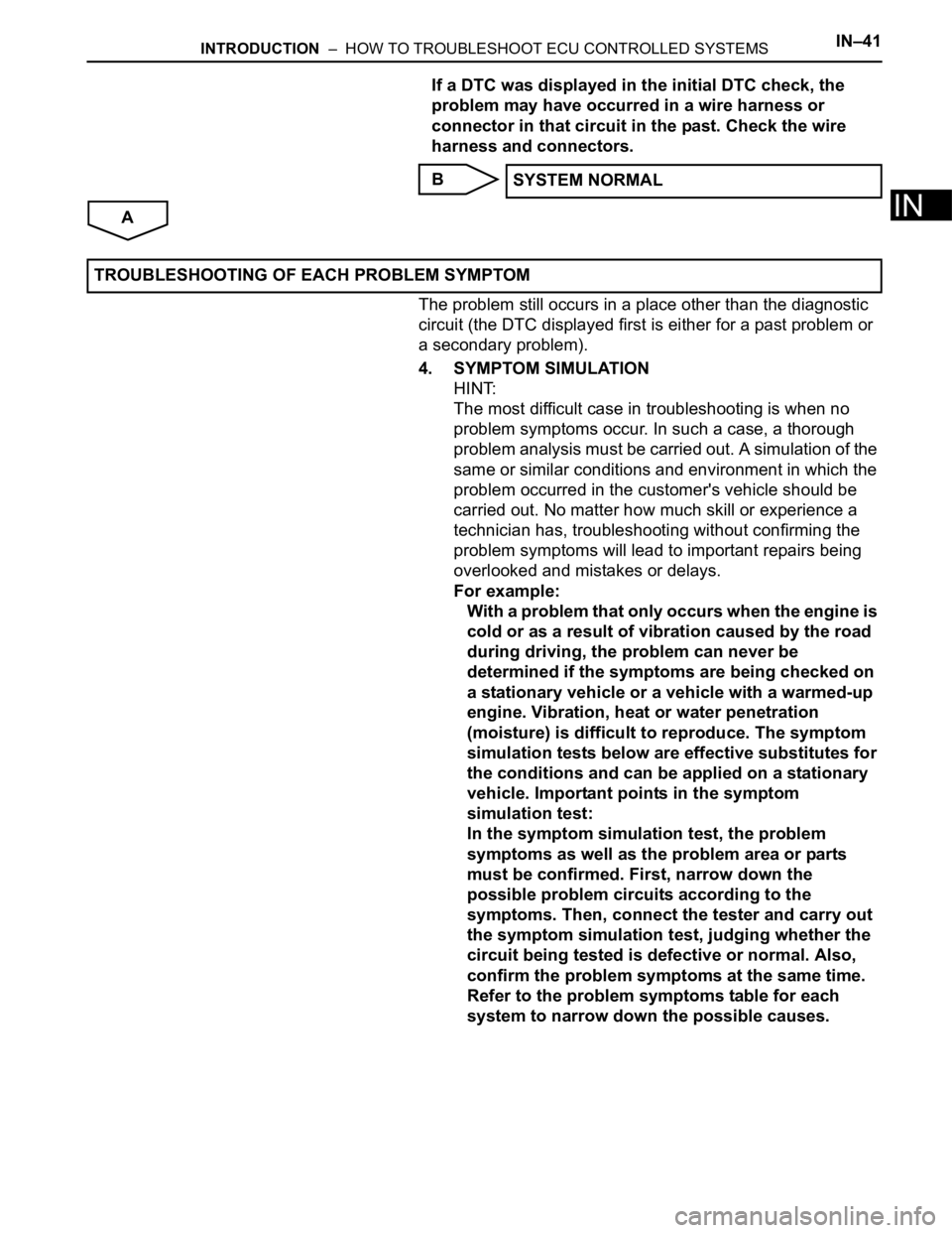
If a DTC was displayed in the initial DTC check, the
problem may have occurred in a wire harness or
connector in that circuit in the past. Check the wire
harness and connectors.
B
A
The problem still occurs in a place other than the diagnostic
circuit (the DTC displayed first is either for a past problem or
a secondary problem).
4. SYMPTOM SIMULATION
HINT:
The most difficult case in troubleshooting is when no
problem symptoms occur. In such a case, a thorough
problem analysis must be carried out. A simulation of the
same or similar conditions and environment in which the
problem occurred in the customer's vehicle should be
carried out. No matter how much skill or experience a
technician has, troubleshooting without confirming the
problem symptoms will lead to important repairs being
overlooked and mistakes or delays.
For example:
With a problem that only occurs when the engine is
cold or as a result of vibration caused by the road
during driving, the problem can never be
determined if the symptoms are being checked on
a stationary vehicle or a vehicle with a warmed-up
engine. Vibration, heat or water penetration
(moisture) is difficult to reproduce. The symptom
simulation tests below are effective substitutes for
the conditions and can be applied on a stationary
vehicle. Important points in the symptom
simulation test:
In the symptom simulation test, the problem
symptoms as well as the problem area or parts
must be confirmed. First, narrow down the
possible problem circuits according to the
symptoms. Then, connect the tester and carry out
the symptom simulation test, judging whether the
circuit being tested is defective or normal. Also,
confirm the problem symptoms at the same time.
Refer to the problem symptoms table for each
system to narrow down the possible causes.SYSTEM NORMAL
TROUBLESHOOTING OF EACH PROBLEM SYMPTOM
Page 70 of 3000
IN–40INTRODUCTION – HOW TO TROUBLESHOOT ECU CONTROLLED SYSTEMS
IN
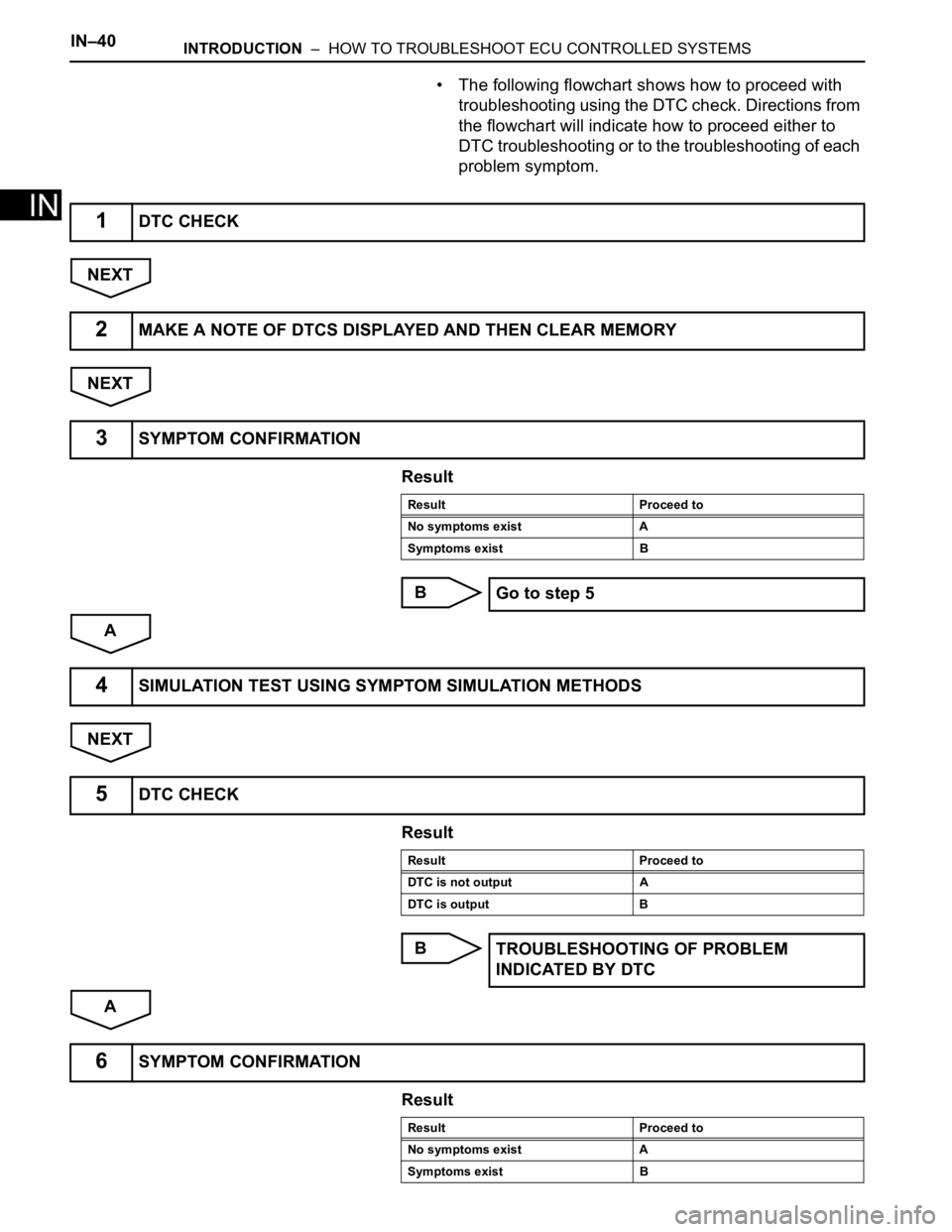
• The following flowchart shows how to proceed with
troubleshooting using the DTC check. Directions from
the flowchart will indicate how to proceed either to
DTC troubleshooting or to the troubleshooting of each
problem symptom.
NEXT
NEXT
Result
B
A
NEXT
Result
B
A
Result
1DTC CHECK
2MAKE A NOTE OF DTCS DISPLAYED AND THEN CLEAR MEMORY
3SYMPTOM CONFIRMATION
Result Proceed to
No symptoms exist A
Symptoms exist B
Go to step 5
4SIMULATION TEST USING SYMPTOM SIMULATION METHODS
5DTC CHECK
Result Proceed to
DTC is not output A
DTC is output B
TROUBLESHOOTING OF PROBLEM
INDICATED BY DTC
6SYMPTOM CONFIRMATION
Result Proceed to
No symptoms exist A
Symptoms exist B
Page 71 of 3000
INTRODUCTION – HOW TO TROUBLESHOOT ECU CONTROLLED SYSTEMSIN–41
IN
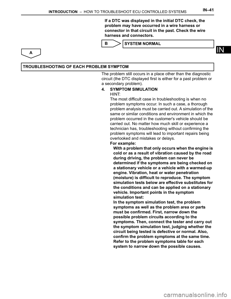
If a DTC was displayed in the initial DTC check, the
problem may have occurred in a wire harness or
connector in that circuit in the past. Check the wire
harness and connectors.
B
A
The problem still occurs in a place other than the diagnostic
circuit (the DTC displayed first is either for a past problem or
a secondary problem).
4. SYMPTOM SIMULATION
HINT:
The most difficult case in troubleshooting is when no
problem symptoms occur. In such a case, a thorough
problem analysis must be carried out. A simulation of the
same or similar conditions and environment in which the
problem occurred in the customer's vehicle should be
carried out. No matter how much skill or experience a
technician has, troubleshooting without confirming the
problem symptoms will lead to important repairs being
overlooked and mistakes or delays.
For example:
With a problem that only occurs when the engine is
cold or as a result of vibration caused by the road
during driving, the problem can never be
determined if the symptoms are being checked on
a stationary vehicle or a vehicle with a warmed-up
engine. Vibration, heat or water penetration
(moisture) is difficult to reproduce. The symptom
simulation tests below are effective substitutes for
the conditions and can be applied on a stationary
vehicle. Important points in the symptom
simulation test:
In the symptom simulation test, the problem
symptoms as well as the problem area or parts
must be confirmed. First, narrow down the
possible problem circuits according to the
symptoms. Then, connect the tester and carry out
the symptom simulation test, judging whether the
circuit being tested is defective or normal. Also,
confirm the problem symptoms at the same time.
Refer to the problem symptoms table for each
system to narrow down the possible causes.SYSTEM NORMAL
TROUBLESHOOTING OF EACH PROBLEM SYMPTOM
Page 181 of 3000
BRAKE CONTROL – ANTI-LOCK BRAKE SYSTEMBC–5
BC
• After the ABS warning light goes off and if
vehicle speed exceeds 50 mph (80 km/h), the
signal check code will be stored again.
Decelerate or stop the vehicle before the
speed reaches 50 mph (80 km/h).
• If the signal check has not been completed,
the ABS warning light blinks while driving
and the ABS system does not operate.
HINT:
When the signal check has been completed, the
ABS warning light goes off while driving and blinks
in the Test Mode pattern while stationary.
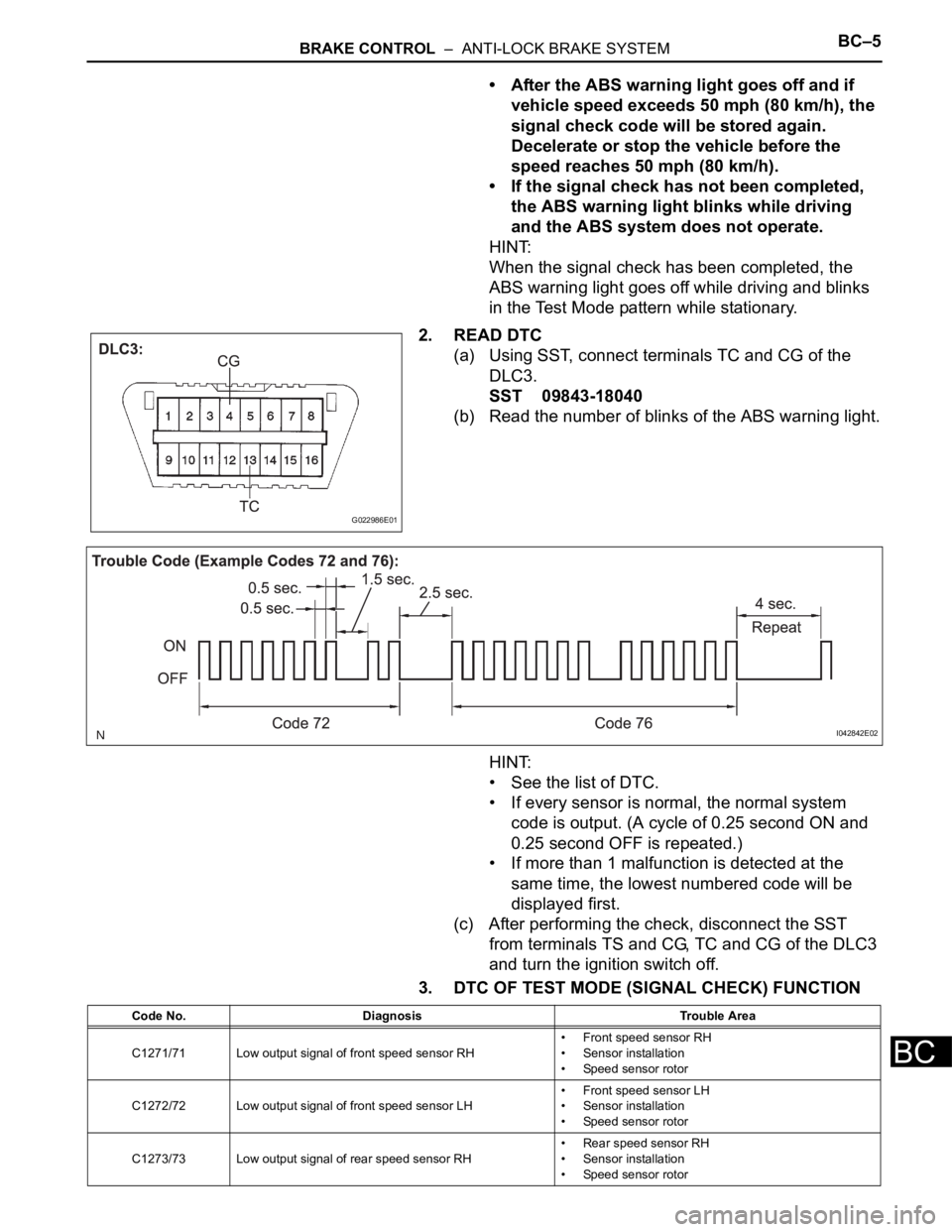
2. READ DTC
(a) Using SST, connect terminals TC and CG of the
DLC3.
SST 09843-18040
(b) Read the number of blinks of the ABS warning light.
HINT:
• See the list of DTC.
• If every sensor is normal, the normal system
code is output. (A cycle of 0.25 second ON and
0.25 second OFF is repeated.)
• If more than 1 malfunction is detected at the
same time, the lowest numbered code will be
displayed first.
(c) After performing the check, disconnect the SST
from terminals TS and CG, TC and CG of the DLC3
and turn the ignition switch off.
3. DTC OF TEST MODE (SIGNAL CHECK) FUNCTION
G022986E01
I042842E02
Code No. Diagnosis Trouble Area
C1271/71 Low output signal of front speed sensor RH• Front speed sensor RH
• Sensor installation
• Speed sensor rotor
C1272/72 Low output signal of front speed sensor LH• Front speed sensor LH
• Sensor installation
• Speed sensor rotor
C1273/73 Low output signal of rear speed sensor RH• Rear speed sensor RH
• Sensor installation
• Speed sensor rotor
Page 243 of 3000
ENGINE IMMOBILISER – ENGINE IMMOBILISER SYSTEMEI–3
EI
HOW TO PROCEED WITH
TROUBLESHOOTING
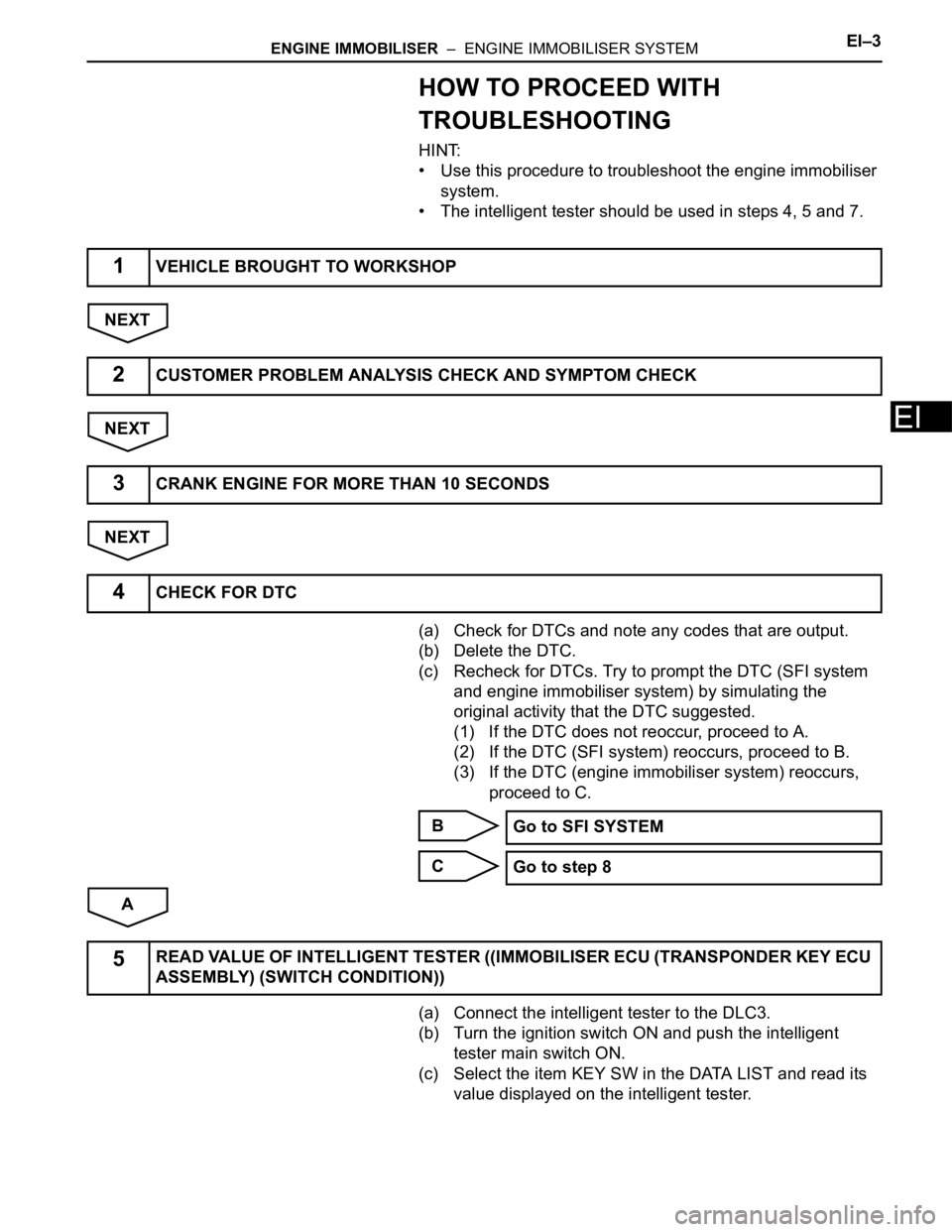
HINT:
• Use this procedure to troubleshoot the engine immobiliser
system.
• The intelligent tester should be used in steps 4, 5 and 7.
NEXT
NEXT
NEXT
(a) Check for DTCs and note any codes that are output.
(b) Delete the DTC.
(c) Recheck for DTCs. Try to prompt the DTC (SFI system
and engine immobiliser system) by simulating the
original activity that the DTC suggested.
(1) If the DTC does not reoccur, proceed to A.
(2) If the DTC (SFI system) reoccurs, proceed to B.
(3) If the DTC (engine immobiliser system) reoccurs,
proceed to C.
B
C
A
(a) Connect the intelligent tester to the DLC3.
(b) Turn the ignition switch ON and push the intelligent
tester main switch ON.
(c) Select the item KEY SW in the DATA LIST and read its
value displayed on the intelligent tester.
1VEHICLE BROUGHT TO WORKSHOP
2CUSTOMER PROBLEM ANALYSIS CHECK AND SYMPTOM CHECK
3CRANK ENGINE FOR MORE THAN 10 SECONDS
4CHECK FOR DTC
Go to SFI SYSTEM
Go to step 8
5READ VALUE OF INTELLIGENT TESTER ((IMMOBILISER ECU (TRANSPONDER KEY ECU
ASSEMBLY) (SWITCH CONDITION))
Page 244 of 3000
EI–4ENGINE IMMOBILISER – ENGINE IMMOBILISER SYSTEM
EI
Transponder key ECU
NG
OK
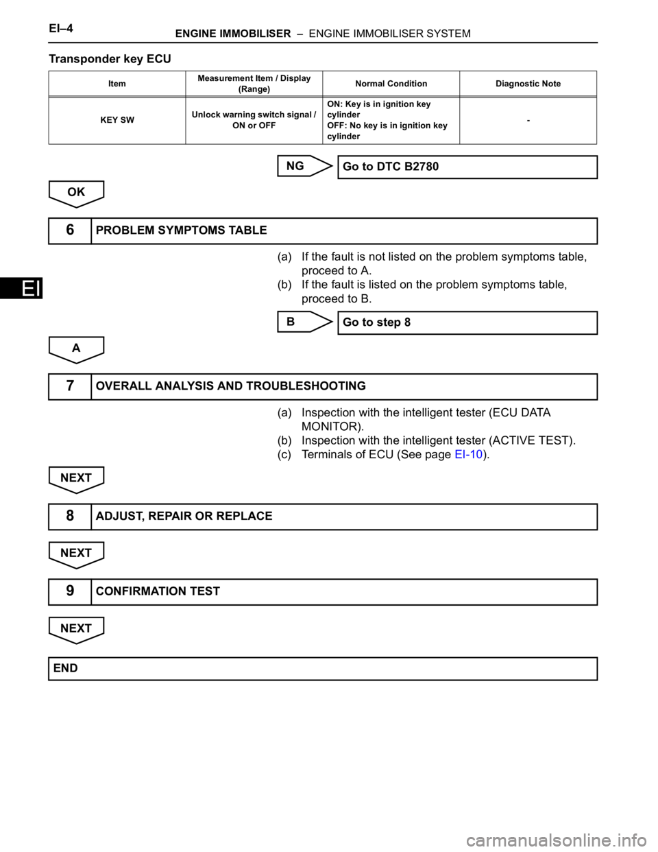
(a) If the fault is not listed on the problem symptoms table,
proceed to A.
(b) If the fault is listed on the problem symptoms table,
proceed to B.
B
A
(a) Inspection with the intelligent tester (ECU DATA
MONITOR).
(b) Inspection with the intelligent tester (ACTIVE TEST).
(c) Terminals of ECU (See page EI-10).
NEXT
NEXT
NEXT
ItemMeasurement Item / Display
(Range)Normal Condition Diagnostic Note
KEY SWUnlock warning switch signal /
ON or OFFON: Key is in ignition key
cylinder
OFF: No key is in ignition key
cylinder-
Go to DTC B2780
6PROBLEM SYMPTOMS TABLE
Go to step 8
7OVERALL ANALYSIS AND TROUBLESHOOTING
8ADJUST, REPAIR OR REPLACE
9CONFIRMATION TEST
END
Page 258 of 3000

AV – 6AUDIO / VISUAL – AUDIO AND VISUAL SYSTEM
AV
(c) ID3 tag and WMA tag
(1) Additional textual information called ID3 tag can
be input to MP3 files. Information such as song
titles and artist names can be stored.
HINT:
This player is compatible with the ID3 tags of ID3
Ver. 1.0 and 1.1, and ID3 Ver. 2.2 and 2.3.
(Number of characters complies with ID3 Ver.
1.0 and 1.1.)
(2) Additional textual information called WMA tag
can be input to WMA files. Information such as
song titles and artist names can be stored.
(d) Usable media
(1) Only CD-ROMs, CD-Rs (CD-Recordable), and
CD-RWs (CD-ReWritable) only can be used to
play MP3/WMA files.
NOTICE:
• CD-Rs and CD-RWs are more easily
affected by a hot and humid environment
than discs used for normal audio CDs. For
this reason, some CD-Rs and CD-RWs
may not be played.
• If there are fingerprints or scratches on
the disc, the disc may not be played or the
CD may skip.
• Some CD-Rs and CD-RWs deteriorate if
they are left in the cabin for a long time.
• Keep CD-Rs and CD-RWs in a storage
case that is impenetrable to light.
(e) Usable media format
(1) Usable media format
HINT:
• As for MP3/WMA files written in any format
other than those above, the contents of the
files may not be played normally or the file
names or folder names may not be displayed
correctly.
• This player is compatible with multi-session
discs and can play CD-Rs and CD-RWs on
which MP3/WMA files are added. However,
only the first session can be played.
• Discs whose first session includes both music
data and MP3 or WMA format data cannot be
played.
(2) Standard and restrictions
Disc format CD-ROM Mode 1, CD-ROM XA Mode 2 Form1
File format ISO9660 Level 1 and Level 2 (joliet)
Maximum directory levels 8 levels
Maximum number of characters for a folder name/file name 32 characters
Maximum number of folders192 (Including empty folders, route folders, and folders that do not
contain MP3/WMA files)
Maximum number of files in a disc 255 (Including non-MP3/WMA files)