Page 260 of 3000

AV – 8AUDIO / VISUAL – AUDIO AND VISUAL SYSTEM
AV
• If an audio system is equipped with a
navigation system, the multi-display unit acts
as the master unit. If the navigation system is
not equipped, the audio head unit acts as the
master unit instead. If the radio and
navigation assembly is equipped, it is the
master unit.
• The radio receiver contains a resistor that is
necessary to enable communication on the
different AVC-LAN circuits.
• The car audio system with an AVC-LAN
circuit has a diagnostic function.
• Each component has a specified number (3-
digit) called a physical address. Each function
has a number (2-digit) called a logical
address.
4. COMMUNICATION SYSTEM OUTLINE
(a) Components of the audio system communicate with
each other via the AVC-LAN.
(b) The master component of the AVC-LAN is a radio
receiver with a 60 to 80
resistor. This is essential
for communication.
(c) If a short circuit or open circuit occurs in the AVC-
LAN circuit, communication is interrupted and the
audio system will stop functioning.
5. DIAGNOSTIC FUNCTION OUTLINE
(a) The audio system has a diagnostic function (the
result is indicated on the master unit).
(b) A 3-digit hexadecimal component code (physical
address) is allocated to each component on the
AVC-LAN. Using this code, the component in the
diagnostic function can be displayed.
Page 264 of 3000
NAVIGATION – NAVIGATION SYSTEMNS–3
NS
SYSTEM DESCRIPTION
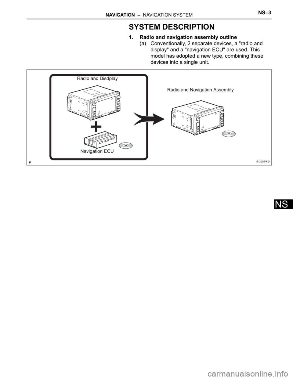
1. Radio and navigation assembly outline
(a) Conventionally, 2 separate devices, a "radio and
display" and a "navigation ECU" are used. This
model has adopted a new type, combining these
devices into a single unit.
E120051E01
Page 265 of 3000
NS–4NAVIGATION – NAVIGATION SYSTEM
NS
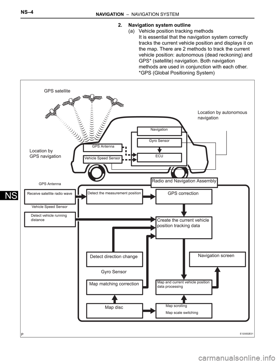
2. Navigation system outline
(a) Vehicle position tracking methods
It is essential that the navigation system correctly
tracks the current vehicle position and displays it on
the map. There are 2 methods to track the current
vehicle position: autonomous (dead reckoning) and
GPS* (satellite) navigation. Both navigation
methods are used in conjunction with each other.
*GPS (Global Positioning System)
E120052E01
Page 266 of 3000
NAVIGATION – NAVIGATION SYSTEMNS–5
NS
Operation Description
Vehicle Position CalculationThe radio and navigation assembly calculates the current vehicle
position (direction and current position) using the direction deviation
signal from the gyro sensor and the running distance signal from the
vehicle speed sensor and creates the driving route.
Map Display ProcessingThe radio and navigation assembly displays the vehicle track on the
map by processing the vehicle position data, vehicle running track,
and map data from the map disc.
Map MatchingThe map data from the map disc is compared to the vehicle position
and running track data. Then, the vehicle position is matched with the
nearest road.
GPS CorrectionThe vehicle position is matched to the position measured by GPS.
Then, the measurement position data from the GPS unit is compared
with the vehicle position and running track data. If the position is
widely different, the GPS measurement position is used.
Distance CorrectionThe running distance signal from the vehicle speed sensor includes
the error caused by tire wear and slippage between the tires and road
surface. Distance correction is performed to account for this. The
radio and navigation assembly automatically offsets the running
distance signal to make up for the difference between it and the
distance data of the map. The offset is automatically updated.
I100028E07
Page 267 of 3000
NS–6NAVIGATION – NAVIGATION SYSTEM
NS
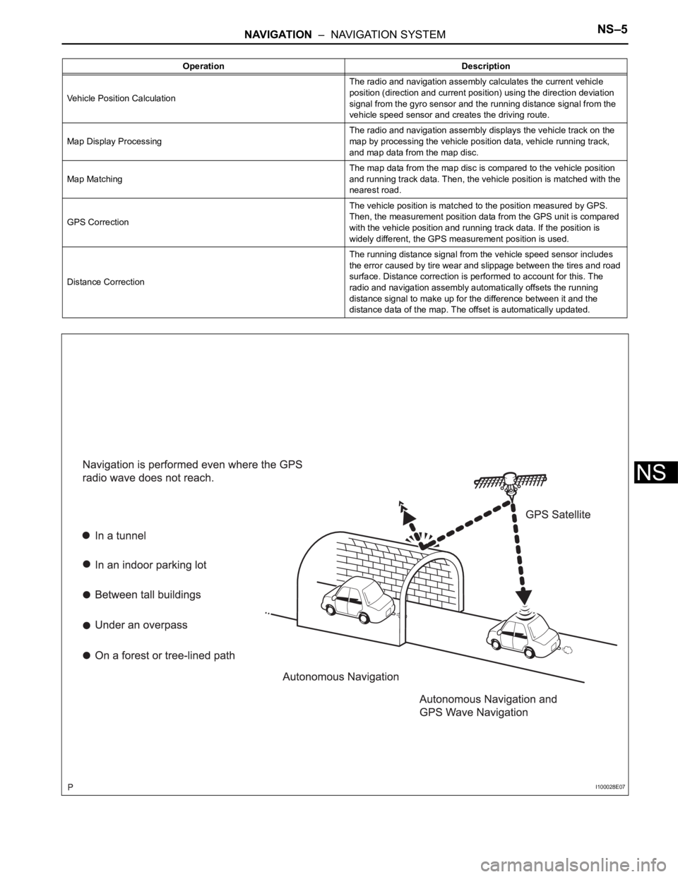
HINT:
The combination of autonomous and GPS
navigation makes it possible to display the vehicle
position even when the vehicle is in places where
the GPS radio wave cannot receive a signal. When
only autonomous navigation is used, however, the
mapping accuracy may slightly decline.
(b) Autonomous navigation
This method determines the relative vehicle position
based on the running track determined by the gyro
and vehicle speed sensors located in the radio and
navigation assembly.
(1) Gyro sensor
Calculates the direction by detecting angular
velocity. It is located in the radio and navigation
assembly.
(2) Vehicle speed sensor
Used to calculate the vehicle running distance.
Page 273 of 3000

NS–12NAVIGATION – NAVIGATION SYSTEM
NS
(b) Playable WMA file standards
(c) ID3 tag and WMA tag
(1) Additional textual information called ID3 tag can
be input to MP3 files. Information such as song
titles and artist names can be stored.
HINT:
This player is compatible with the ID3 tags of ID3
Ver. 1.0 and 1.1, and ID3 Ver. 2.2 and 2.3.
(Number of characters complies with ID3 Ver.
1.0 and 1.1.)
(2) Additional textual information called WMA tag
can be input to WMA files. Information such as
song titles and artist names can be stored.
(d) Usable media
(1) Only CD-ROMs, CD-Rs (CD-Recordable), and
CD-RWs (CD-ReWritable) only can be used to
play MP3/WMA files.
NOTICE:
• CD-Rs and CD-RWs are more easily
affected by a hot and humid environment
than discs used for normal audio CDs. For
this reason, some CD-Rs and CD-RWs
may not be played.
• If there are fingerprints or scratches on
the disc, the disc may not be played or the
CD may skip.
• Some CD-Rs and CD-RWs deteriorate if
they are left in the cabin for a long time.
• Keep CD-Rs and CD-RWs in a storage
case that is impenetrable to light.
(e) Usable media format
(1) Usable media format
HINT:
• As for MP3/WMA files written in any format
other than those above, the contents of the
files may not be played normally or the file
names or folder names may not be displayed
correctly.
• This player is compatible with multi-session
discs and can play CD-Rs and CD-RWs on
which MP3/WMA files are added. However,
only the first session can be played.
• Discs whose first session includes both music
data and MP3 or WMA format data cannot be
played.
Compatible standard WMA Ver. 7, 8, and 9
Compatible sampling frequency 32, 44.1, 48 (kHz)
Compatible bit rate• Ver. 7, 8: CBR48, 64, 80, 96, 128, 160, 192 (kbps)
• Ver. 9: CBR48, 64, 80, 96, 128, 160, 192, 256, 320 (kbps)
• Compatible with playback of channel 2 only
Disc format CD-ROM Mode 1, CD-ROM XA Mode 2 Form 1
File format ISO9660 Level 1 and Level 2 (joliet)
Page 275 of 3000

NS–14NAVIGATION – NAVIGATION SYSTEM
NS
(b) Purpose:
Recently, car audio systems have rapidly developed
and the functions have vastly changed. The
conventional car audio system is being integrated
with multi-media interfaces similar to those in
navigation systems. At the same time, customers
are demanding higher quality from their audio
systems. This is merely an overview of the
standardization background. The specific purposes
are as follows:
(1) To solve sound problems, etc. caused by using
components of different manufacturers through
signal standardization.
(2) To allow each manufacturer to concentrate on
developing products they do best. From this,
reasonably priced products can be produced.
HINT:
• If a short to +B or short to ground is detected
in the AVC-LAN circuit, communication is
interrupted and the audio system will stop
functioning.
• If an audio system is equipped with a
navigation system, the multi-display unit acts
as the master unit.
If the navigation system is not equipped, the
audio head unit acts as the master unit
instead. If the radio and navigation assembly
is equipped, it is the master unit.
• The radio and navigation assembly contains
a resistor that is necessary to enable
communication on the different AVC-LAN
circuits.
• The car audio system with an AVC-LAN
circuit has a diagnostic function.
• Each component has a specified number (3-
digit) called a physical address. Each function
has a number (2-digit) called a logical
address.
7. Communication system outline
(a) Components of the navigation system communicate
with each other via the AVC-LAN.
(b) The radio and navigation assembly has enough
resistance (60 to 80
) necessary for
communication.
(c) If a short circuit or open circuit occurs in the AVC-
LAN circuit, communication is interrupted and the
navigation system will stop functioning.
8. Diagnostic function outline
(a) The audio system has a diagnostic function (the
result is indicated on the master unit).
(b) A 3-digit hexadecimal component code (physical
address) is allocated to each component on the
AVC-LAN. Using this code, the component in the
diagnostic function can be displayed.
Page 277 of 3000

PARK ASSIST / MONITORING – REAR VIEW MONITOR SYSTEMPM–3
PM
SYSTEM DESCRIPTION
1. GENERAL
(a) To assist the driver with parking the vehicle by
displaying an image of the area behind the vehicle,
this system has a television camera mounted on the
luggage compartment door. The system displays
the image on the radio and navigation assembly.
(b) This system consists of the following components:
(1) Radio and navigation assembly
(2) Television camera assembly
(c) This system is equipped with a self-diagnosis
system, which is operated on a dedicated window
that appears on the display panel, just as in the
navigation system.
2. FUNCTION OF COMPONENTS
(a) The radio and navigation assembly controls the
system by using information from the following
components:
3. OPERATION EXPLANATION
(a) The radio and navigation assembly receives the R
position signal from the park / neutral position switch
when the shift lever is moved to the R position. After
receiving the R position signal, the radio and
navigation assembly switches from the navigation
system to the rear view monitor system.
4. NOTES FOR REAR VIEW MONITOR
(a) Notes for the rear view monitor.
(1) The rear view monitor may not function properly
if subjected to a severe blow by any hard object.
(2) Do not "scrub" the cover part of the camera
(resin made). Scrubbing it may scratch the cover
and affect the image. Prevent organic solvents,
waxes, bond removing solvents, or glass coating
from adhering to the cover. Clean it off
immediately, and wash with water.
(3) Exposing the camera to a sudden temperature
change may affect proper functioning of the
camera.
(4) A clear image may not appear if the camera is
dirty with snow, mud, etc. In that case, wash it
with water and wipe off the lens. Use a detergent
to remove dirt if necessary.
Item Function
Television Camera Assembly• Mounted on the luggage compartment door to transmit the rear
view of the vehicle to the radio and navigation assembly.
• A color video camera that uses a CCD (Charge Coupled Device)
and a wide-angle lens.
Radio and Navigation Assembly• Transmits video signals, which contain an image of the area
behind the vehicle taken with the television camera assembly.
• Radio and navigation assembly effects control of the system by
receiving the shift position signal from park/neutral position switch.
• Displays the rear view monitor image on the display panel.
Park/Neutral Position SwitchTransmits a reverse shift position signal to the radio and navigation
assembly.