Page 281 of 3000
WS–6WINDSHIELD / WINDOWGLASS – POWER WINDOW CONTROL SYSTEM (w/ Jam Protec-
tion Function)
WS
CUSTOMIZE PARAMETERS
HINT:
The following item can be customized.
NOTICE:
• After confirming whether the items requested by the
customer are applicable or not for customization,
perform the customize operation.
• Be sure to record the current settings before
customizing.
• When troubleshooting, make sure that the item in
question is not set to "OFF" as a result of
customization (Example: For the system, "the wireless
function does not operate", first check that the
wireless function is not set to "OFF", then perform
troubleshooting).
POWER WINDOW
DISPLAY (ITEM) DEFAULT CONTENTS SETTING
IG OFF P/W ONAfter ignition switch OFF, power window control permission signal is
outputON / OFF
Page 314 of 3000
ES–102GR-FE ENGINE CONTROL SYSTEM – SFI SYSTEM
ES
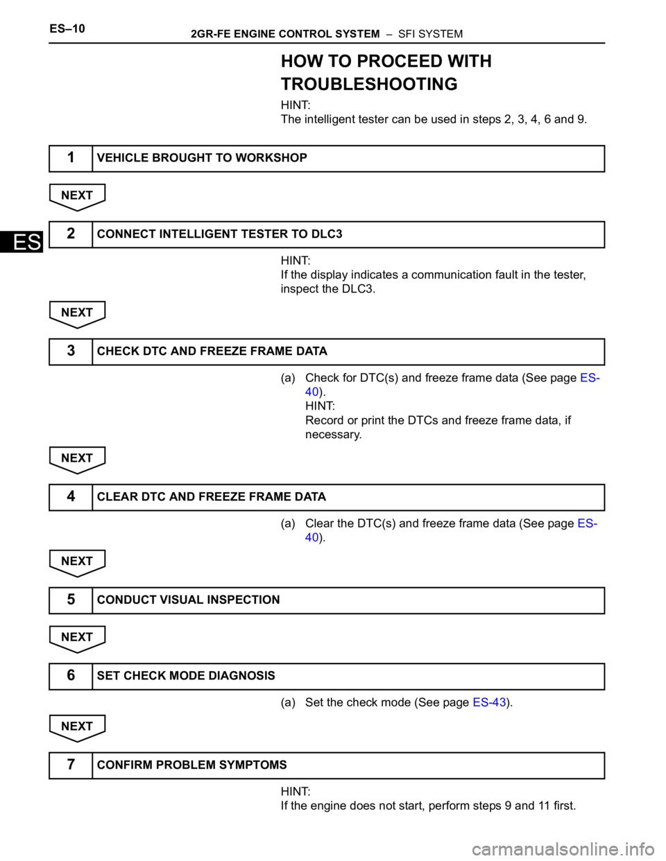
HOW TO PROCEED WITH
TROUBLESHOOTING
HINT:
The intelligent tester can be used in steps 2, 3, 4, 6 and 9.
NEXT
HINT:
If the display indicates a communication fault in the tester,
inspect the DLC3.
NEXT
(a) Check for DTC(s) and freeze frame data (See page ES-
40).
HINT:
Record or print the DTCs and freeze frame data, if
necessary.
NEXT
(a) Clear the DTC(s) and freeze frame data (See page ES-
40).
NEXT
NEXT
(a) Set the check mode (See page ES-43).
NEXT
HINT:
If the engine does not start, perform steps 9 and 11 first.
1VEHICLE BROUGHT TO WORKSHOP
2CONNECT INTELLIGENT TESTER TO DLC3
3CHECK DTC AND FREEZE FRAME DATA
4CLEAR DTC AND FREEZE FRAME DATA
5CONDUCT VISUAL INSPECTION
6SET CHECK MODE DIAGNOSIS
7CONFIRM PROBLEM SYMPTOMS
Page 324 of 3000
ES–2562GR-FE ENGINE CONTROL SYSTEM – SFI SYSTEM
ES
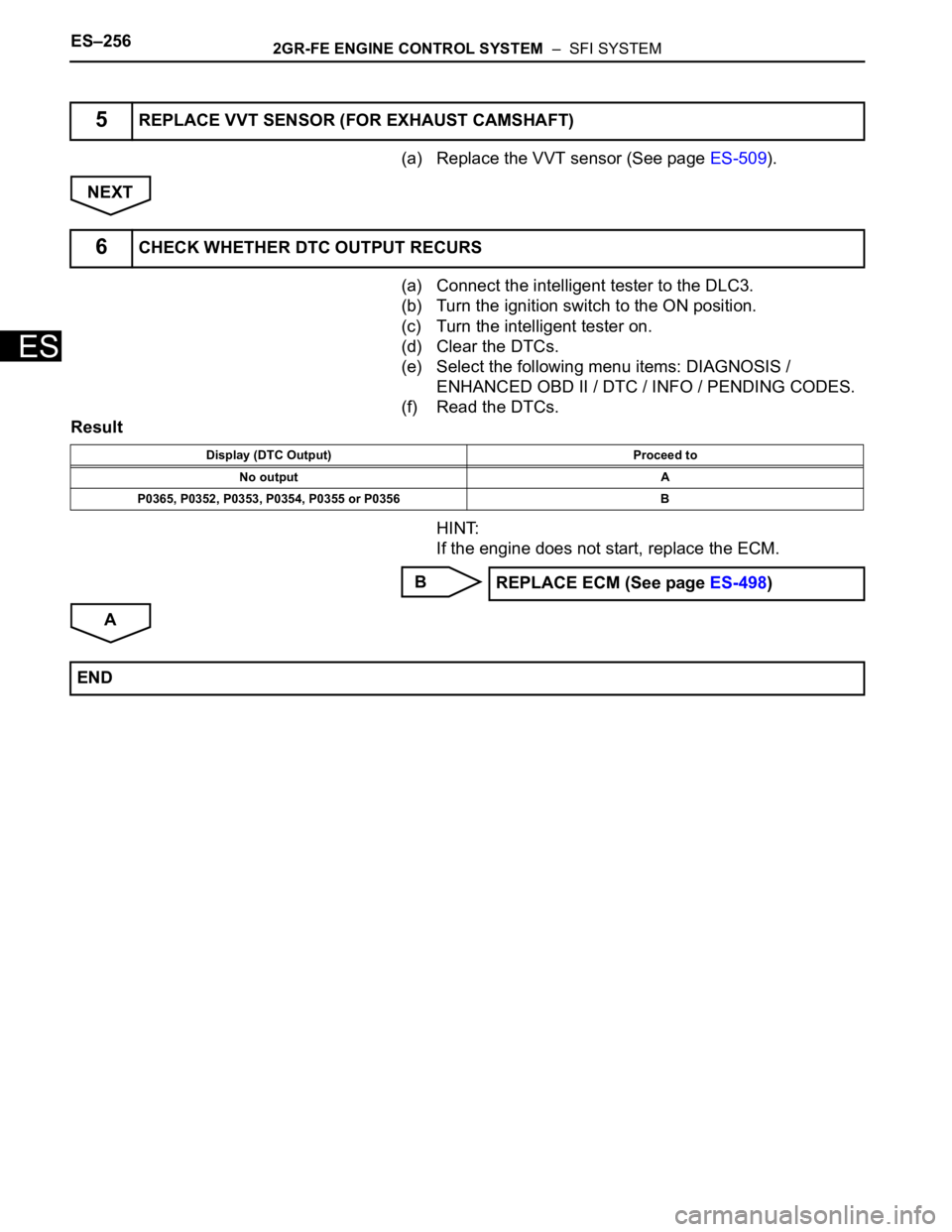
(a) Replace the VVT sensor (See page ES-509).
NEXT
(a) Connect the intelligent tester to the DLC3.
(b) Turn the ignition switch to the ON position.
(c) Turn the intelligent tester on.
(d) Clear the DTCs.
(e) Select the following menu items: DIAGNOSIS /
ENHANCED OBD II / DTC / INFO / PENDING CODES.
(f) Read the DTCs.
Result
HINT:
If the engine does not start, replace the ECM.
B
A
5REPLACE VVT SENSOR (FOR EXHAUST CAMSHAFT)
6CHECK WHETHER DTC OUTPUT RECURS
Display (DTC Output) Proceed to
No output A
P0365, P0352, P0353, P0354, P0355 or P0356 B
REPLACE ECM (See page ES-498)
END
Page 329 of 3000
2GR-FE ENGINE CONTROL SYSTEM – SFI SYSTEMES–261
ES
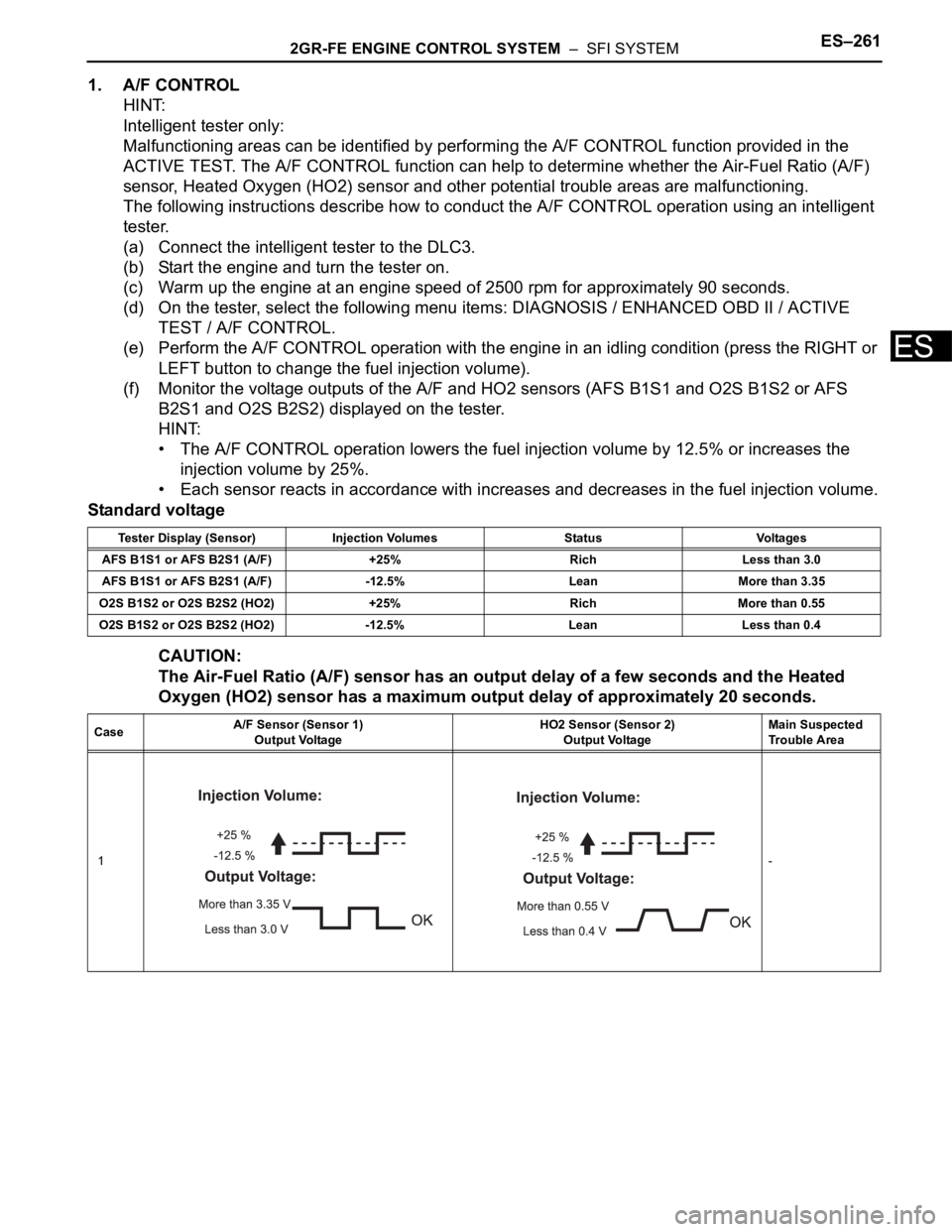
1. A/F CONTROL
HINT:
Intelligent tester only:
Malfunctioning areas can be identified by performing the A/F CONTROL function provided in the
ACTIVE TEST. The A/F CONTROL function can help to determine whether the Air-Fuel Ratio (A/F)
sensor, Heated Oxygen (HO2) sensor and other potential trouble areas are malfunctioning.
The following instructions describe how to conduct the A/F CONTROL operation using an intelligent
tester.
(a) Connect the intelligent tester to the DLC3.
(b) Start the engine and turn the tester on.
(c) Warm up the engine at an engine speed of 2500 rpm for approximately 90 seconds.
(d) On the tester, select the following menu items: DIAGNOSIS / ENHANCED OBD II / ACTIVE
TEST / A/F CONTROL.
(e) Perform the A/F CONTROL operation with the engine in an idling condition (press the RIGHT or
LEFT button to change the fuel injection volume).
(f) Monitor the voltage outputs of the A/F and HO2 sensors (AFS B1S1 and O2S B1S2 or AFS
B2S1 and O2S B2S2) displayed on the tester.
HINT:
• The A/F CONTROL operation lowers the fuel injection volume by 12.5% or increases the
injection volume by 25%.
• Each sensor reacts in accordance with increases and decreases in the fuel injection volume.
Standard voltage
CAUTION:
The Air-Fuel Ratio (A/F) sensor has an output delay of a few seconds and the Heated
Oxygen (HO2) sensor has a maximum output delay of approximately 20 seconds.
Tester Display (Sensor) Injection Volumes Status Voltages
AFS B1S1 or AFS B2S1 (A/F) +25% Rich Less than 3.0
AFS B1S1 or AFS B2S1 (A/F) -12.5% Lean More than 3.35
O2S B1S2 or O2S B2S2 (HO2) +25% Rich More than 0.55
O2S B1S2 or O2S B2S2 (HO2) -12.5% Lean Less than 0.4
CaseA/F Sensor (Sensor 1)
Output VoltageHO2 Sensor (Sensor 2)
Output VoltageMain Suspected
Trouble Area
1-
Page 330 of 3000
ES–2622GR-FE ENGINE CONTROL SYSTEM – SFI SYSTEM
ES
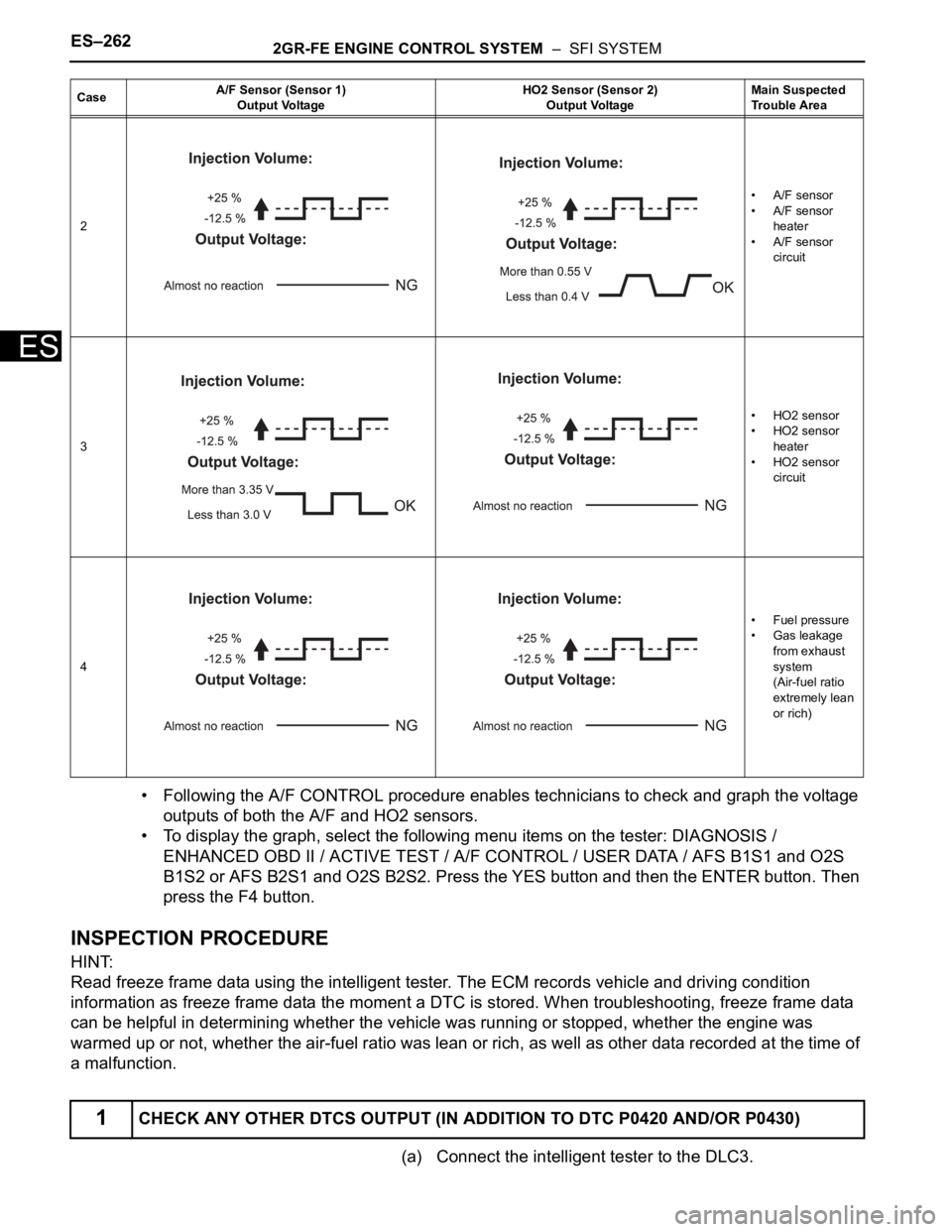
• Following the A/F CONTROL procedure enables technicians to check and graph the voltage
outputs of both the A/F and HO2 sensors.
• To display the graph, select the following menu items on the tester: DIAGNOSIS /
ENHANCED OBD II / ACTIVE TEST / A/F CONTROL / USER DATA / AFS B1S1 and O2S
B1S2 or AFS B2S1 and O2S B2S2. Press the YES button and then the ENTER button. Then
press the F4 button.
INSPECTION PROCEDURE
HINT:
Read freeze frame data using the intelligent tester. The ECM records vehicle and driving condition
information as freeze frame data the moment a DTC is stored. When troubleshooting, freeze frame data
can be helpful in determining whether the vehicle was running or stopped, whether the engine was
warmed up or not, whether the air-fuel ratio was lean or rich, as well as other data recorded at the time of
a malfunction.
(a) Connect the intelligent tester to the DLC3.
2• A/F sensor
• A/F sensor
heater
• A/F sensor
circuit
3• HO2 sensor
• HO2 sensor
heater
• HO2 sensor
circuit
4•Fuel pressure
• Gas leakage
from exhaust
system
(Air-fuel ratio
extremely lean
or rich)
1CHECK ANY OTHER DTCS OUTPUT (IN ADDITION TO DTC P0420 AND/OR P0430)
CaseA/F Sensor (Sensor 1)
Output VoltageHO2 Sensor (Sensor 2)
Output VoltageMain Suspected
Trouble Area
Page 331 of 3000
2GR-FE ENGINE CONTROL SYSTEM – SFI SYSTEMES–263
ES
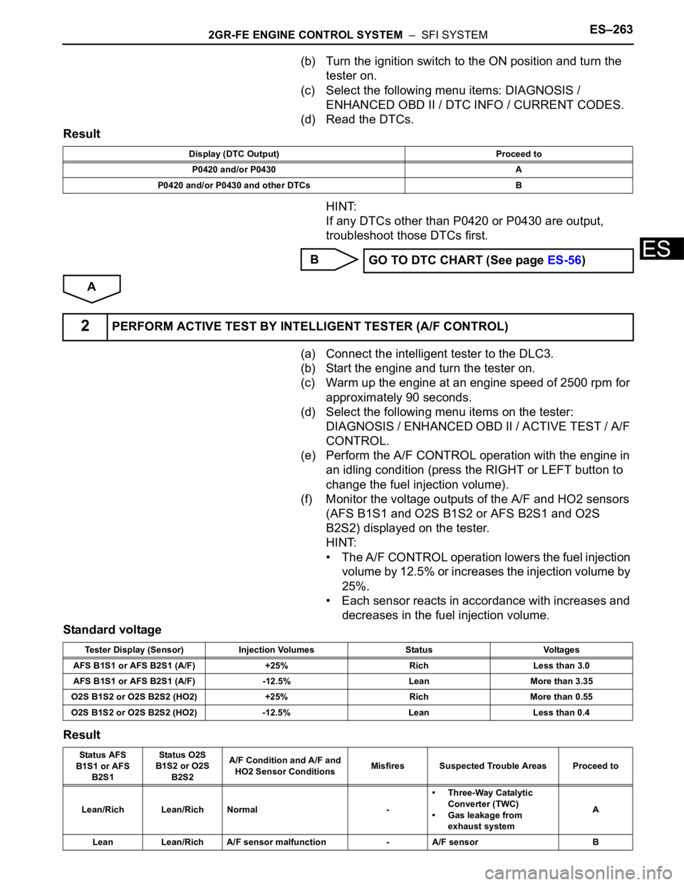
(b) Turn the ignition switch to the ON position and turn the
tester on.
(c) Select the following menu items: DIAGNOSIS /
ENHANCED OBD II / DTC INFO / CURRENT CODES.
(d) Read the DTCs.
Result
HINT:
If any DTCs other than P0420 or P0430 are output,
troubleshoot those DTCs first.
B
A
(a) Connect the intelligent tester to the DLC3.
(b) Start the engine and turn the tester on.
(c) Warm up the engine at an engine speed of 2500 rpm for
approximately 90 seconds.
(d) Select the following menu items on the tester:
DIAGNOSIS / ENHANCED OBD II / ACTIVE TEST / A/F
CONTROL.
(e) Perform the A/F CONTROL operation with the engine in
an idling condition (press the RIGHT or LEFT button to
change the fuel injection volume).
(f) Monitor the voltage outputs of the A/F and HO2 sensors
(AFS B1S1 and O2S B1S2 or AFS B2S1 and O2S
B2S2) displayed on the tester.
HINT:
• The A/F CONTROL operation lowers the fuel injection
volume by 12.5% or increases the injection volume by
25%.
• Each sensor reacts in accordance with increases and
decreases in the fuel injection volume.
Standard voltage
Result
Display (DTC Output) Proceed to
P0420 and/or P0430 A
P0420 and/or P0430 and other DTCs B
GO TO DTC CHART (See page ES-56)
2PERFORM ACTIVE TEST BY INTELLIGENT TESTER (A/F CONTROL)
Tester Display (Sensor) Injection Volumes Status Voltages
AFS B1S1 or AFS B2S1 (A/F) +25% Rich Less than 3.0
AFS B1S1 or AFS B2S1 (A/F) -12.5% Lean More than 3.35
O2S B1S2 or O2S B2S2 (HO2) +25% Rich More than 0.55
O2S B1S2 or O2S B2S2 (HO2) -12.5% Lean Less than 0.4
Status AFS
B1S1 or AFS
B2S1Status O2S
B1S2 or O2S
B2S2A/F Condition and A/F and
HO2 Sensor ConditionsMisfires Suspected Trouble Areas Proceed to
Lean/Rich Lean/Rich Normal -• Three-Way Catalytic
Converter (TWC)
• Gas leakage from
exhaust systemA
Lean Lean/Rich A/F sensor malfunction - A/F sensor B
Page 348 of 3000

ES–222GR-FE ENGINE CONTROL SYSTEM – SFI SYSTEM
ES
CHECKING MONITOR STATUS
The purpose of the monitor result (mode 06) is to allow
access to the results for on-board diagnostic monitoring tests
of specific components/systems that are not continuously
monitored. Examples are catalyst, evaporative emission
(EVAP) and thermostat.
The monitor result allows the OBD II scan tool to display the
monitor status, test value, minimum test limit and maximum
test limit. These data are displayed after the vehicle has been
driven to run the monitor.
When the test value is not between the minimum test limit
and maximum test limit, the ECM (PCM) interprets this as a
malfunction. When the component is not malfunctioning, if the
difference of the test value and test limit is very small, the
component will malfunction in the near future.
Perform the following instructions to view the monitor status.
Although the Lexus diagnostic tester is used in the following
instructions, it can be checked using a generic OBD II scan
tool. Refer to your scan tool operator's manual for specific
procedures.
1. PERFORM MONITOR DRIVE PATTERN
The monitor results and test values can be checked with
the OBD II scan tool or the intelligent tester. The engine
control module (ECM) monitors the emissions-related
components such as the thermostat, catalyst converter
and evaporative emissions (EVAP), and determines
whether they are functioning normally or not. When
monitoring is finished, the ECM stores the monitor
results and the test values. The monitor result indicates
whether the component is functioning normally or not.
The test value is the value that was used to determine
the monitor result. If the test value is outside of the test
limit (malfunction criterion), the ECM determines the
component is malfunctioning. Some emissions-related
components have multiple test values to determine
monitor result. If one of these test values is outside of the
test limit, the ECM determines the component is
malfunctioning.
(a) Connect the intelligent tester to the DLC3.
(b) Start the engine and turn the tester on.
(c) Clear the DTCs.
(d) Run the vehicle in accordance with the applicable
drive pattern described in READINESS MONITOR
DRIVE PATTERN (See page ES-22). DO NOT turn
the ignition switch off.
NOTICE:
The test results will be lost if the ignition switch
is turned off.
Page 353 of 3000
2GR-FE ENGINE CONTROL SYSTEM – SFI SYSTEMES–27
ES
Contents:
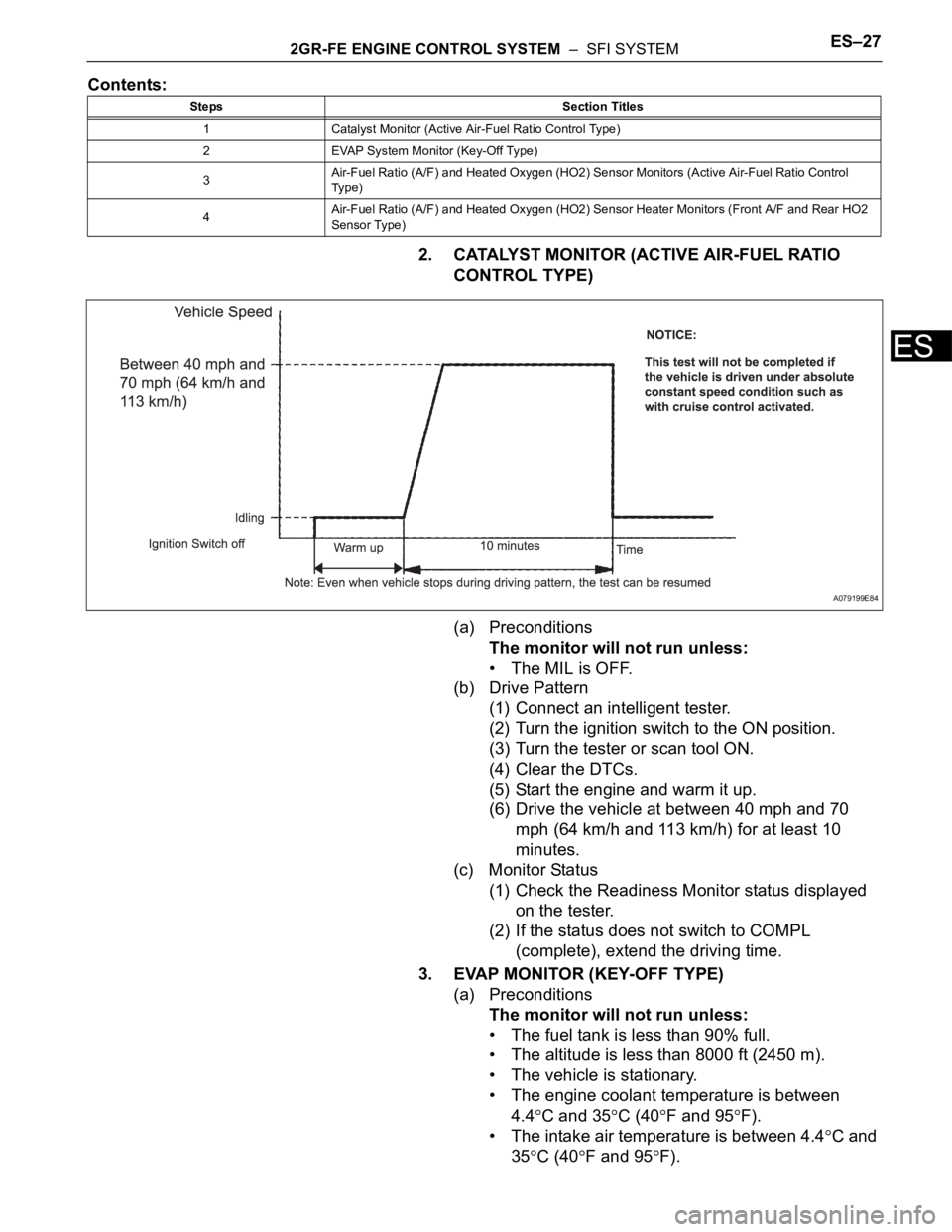
2. CATALYST MONITOR (ACTIVE AIR-FUEL RATIO
CONTROL TYPE)
(a) Preconditions
The monitor will not run unless:
• The MIL is OFF.
(b) Drive Pattern
(1) Connect an intelligent tester.
(2) Turn the ignition switch to the ON position.
(3) Turn the tester or scan tool ON.
(4) Clear the DTCs.
(5) Start the engine and warm it up.
(6) Drive the vehicle at between 40 mph and 70
mph (64 km/h and 113 km/h) for at least 10
minutes.
(c) Monitor Status
(1) Check the Readiness Monitor status displayed
on the tester.
(2) If the status does not switch to COMPL
(complete), extend the driving time.
3. EVAP MONITOR (KEY-OFF TYPE)
(a) Preconditions
The monitor will not run unless:
• The fuel tank is less than 90% full.
• The altitude is less than 8000 ft (2450 m).
• The vehicle is stationary.
• The engine coolant temperature is between
4.4
C and 35C (40F and 95F).
• The intake air temperature is between 4.4
C and
35
C (40F and 95F).
Steps Section Titles
1 Catalyst Monitor (Active Air-Fuel Ratio Control Type)
2 EVAP System Monitor (Key-Off Type)
3Air-Fuel Ratio (A/F) and Heated Oxygen (HO2) Sensor Monitors (Active Air-Fuel Ratio Control
Ty p e )
4Air-Fuel Ratio (A/F) and Heated Oxygen (HO2) Sensor Heater Monitors (Front A/F and Rear HO2
Sensor Type)
A079199E84