Page 414 of 3000

ES–1082GR-FE ENGINE CONTROL SYSTEM – SFI SYSTEM
ES
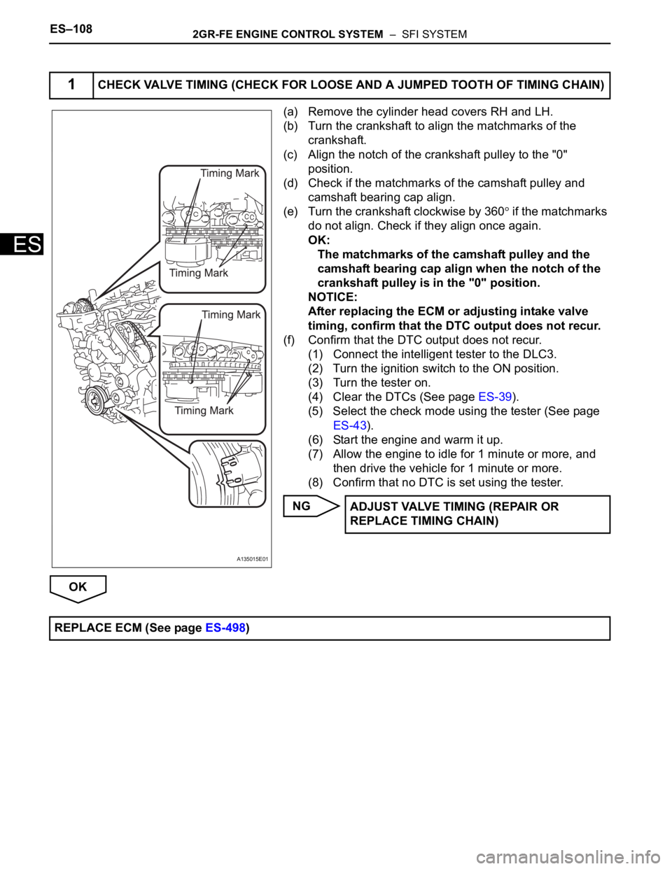
(a) Remove the cylinder head covers RH and LH.
(b) Turn the crankshaft to align the matchmarks of the
crankshaft.
(c) Align the notch of the crankshaft pulley to the "0"
position.
(d) Check if the matchmarks of the camshaft pulley and
camshaft bearing cap align.
(e) Turn the crankshaft clockwise by 360
if the matchmarks
do not align. Check if they align once again.
OK:
The matchmarks of the camshaft pulley and the
camshaft bearing cap align when the notch of the
crankshaft pulley is in the "0" position.
NOTICE:
After replacing the ECM or adjusting intake valve
timing, confirm that the DTC output does not recur.
(f) Confirm that the DTC output does not recur.
(1) Connect the intelligent tester to the DLC3.
(2) Turn the ignition switch to the ON position.
(3) Turn the tester on.
(4) Clear the DTCs (See page ES-39).
(5) Select the check mode using the tester (See page
ES-43).
(6) Start the engine and warm it up.
(7) Allow the engine to idle for 1 minute or more, and
then drive the vehicle for 1 minute or more.
(8) Confirm that no DTC is set using the tester.
NG
OK
1CHECK VALVE TIMING (CHECK FOR LOOSE AND A JUMPED TOOTH OF TIMING CHAIN)
A135015E01
ADJUST VALVE TIMING (REPAIR OR
REPLACE TIMING CHAIN)
REPLACE ECM (See page ES-498)
Page 686 of 3000

2GR-FE ENGINE CONTROL SYSTEM – SFI SYSTEMES–393
ES
MONITOR DESCRIPTION
5 hours after the ignition switch is turned off, the soak timer activates the ECM to begin the EVAP system
monitor. While the engine is running, the ECM monitors the synchronization of the soak timer and the
CPU clock. If these two are not synchronized, the ECM interprets this as a malfunction, illuminates the
MIL and sets the DTC (2 trip detection logic).
MONITOR STRATEGY
TYPICAL ENABLING CONDITIONS
TYPICAL MALFUNCTION THRESHOLDS
INSPECTION PROCEDURE
HINT:
• DTC P2610 is set if an internal ECM problem is detected. Diagnostic procedures are not required.
ECM replacement is required.
• Read freeze frame data using the intelligent tester. The ECM records vehicle and driving condition
information as freeze frame data the moment a DTC is stored. When troubleshooting, freeze frame
data can be helpful in determining whether the vehicle was running or stopped, whether the engine
was warmed up or not, whether the air-fuel ratio was lean or rich, as well as other data recorded at the
time of a malfunction.
(a) Replace the ECM (See page ES-498).
NEXT
(a) Connect the intelligent tester to the DLC3.
(b) Turn the ignition switch to the ON position.
(c) Clear the DTCs (See page ES-39).
(d) Start the engine and wait for 10 minutes or more.
Required Sensors / Components ECM
Frequency of Operation Once per driving cycle
Duration 10 minutes
MIL Operation 2 driving cycles
Sequence of Operation None
The monitor will run whenever these DTCs are not
presentNone
Ignition switch ON
Engine Running
Battery voltage 8 V or more
Sta r t e r OF F
Soak timer measurement when ECM CPU clock counts
10 minutesLess than 7 minutes or more than 13 minutes
1REPLACE ECM
2CHECK WHETHER DTC OUTPUT RECURS
Page 892 of 3000
2GR-FE ENGINE MECHANICAL – ENGINE UNITEM–87
EM
30. REMOVE NO. 1 CHAIN TENSIONER ASSEMBLY
(a) Move the stopper plate upward to release the lock,
and push the plunger deep into the tensioner.
(b) Move the stopper plate downward to set the lock,
and insert a pin of
1.27 mm (0.05 in.) into the
stopper plate's hole.
(c) Remove the 2 bolts and No. 1 chain tensioner
assembly.
31. REMOVE CHAIN TENSIONER SLIPPER
(a) Remove the chain tensioner slipper.
32. REMOVE CHAIN SUB-ASSEMBLY
(a) Turn the crankshaft counterclockwise 10
to loosen
the chain sub-assembly of the crankshaft timing
sprocket.
(b) Remove the pulley set bolt.
(c) Remove the chain sub-assembly from the
crankshaft timing sprocket and place it on the
crankshaft.
(d) Turn the camshaft timing gear assembly on the
bank 1 clockwise (approximately 60
) and set it as
shown in the illustration. Be sure to loosen the chain
between the banks.
(e) Remove the chain.
A124589E02
A095165
A134897E02
A134890
A095682E05
Page 960 of 3000
2GR-FE ENGINE MECHANICAL – ENGINE UNITEM–151
EM
(b) Do not pass the chain over the crankshaft, just put it
on it.
(c) Turn the camshaft timing gear assembly on the
bank 1 counterclockwise to tighten the chain
between the banks.
NOTICE:
When the idle sprocket is reused, align the chain
plate with the mark where the plate had been in
order to tighten the chain between the banks.
(d) Align the mark plate and timing marks as shown in
the illustration and install the chain onto the
crankshaft timing sprocket.
HINT:
The crankshaft mark plate is yellow.
(e) Temporarily tighten the pulley set bolt.
A134890
A122184E04
A132224E03
Page 961 of 3000
EM–1522GR-FE ENGINE MECHANICAL – ENGINE UNIT
EM
(f) Turn the crankshaft clockwise to set it to the RH
block bore center line (TDC / compression).
43. INSTALL CHAIN TENSIONER SLIPPER
(a) Install the chain tensioner slipper.
44. INSTALL NO. 1 CHAIN TENSIONER ASSEMBLY
(a) Move the stopper plate upward to release the lock,
and push the plunger deep into the tensioner.
(b) Move the stopper plate downward to set the lock,
and insert a hexagon wrench into the hole of the
stopper plate.
(c) Install the chain tensioner with the 2 bolts.
Torque: 10 N*m (102 kgf*cm, 7 ft.*lbf)
A129691E04
A132225E01
A095165
Page 981 of 3000

2GR-FE ENGINE MECHANICAL – DRIVE BELTEM–7
EM
INSTALLATION
1. INSTALL V-RIBBED BELT
(a) Install the V-ribbed belt.
(b) Using SST, turn the belt tensioner counterclockwise
and remove the bar.
SST 09249-63010
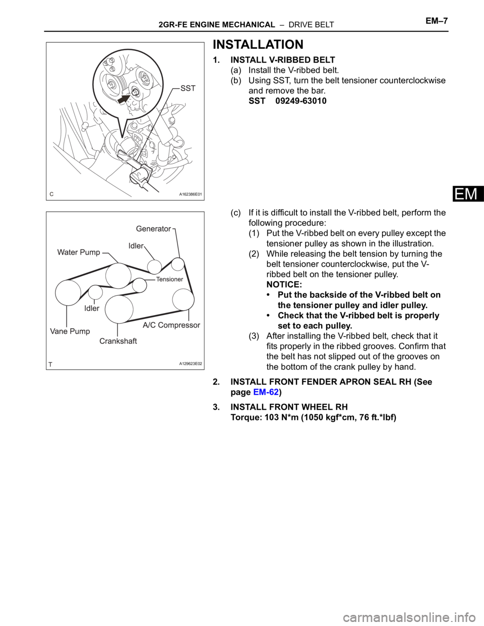
(c) If it is difficult to install the V-ribbed belt, perform the
following procedure:
(1) Put the V-ribbed belt on every pulley except the
tensioner pulley as shown in the illustration.
(2) While releasing the belt tension by turning the
belt tensioner counterclockwise, put the V-
ribbed belt on the tensioner pulley.
NOTICE:
• Put the backside of the V-ribbed belt on
the tensioner pulley and idler pulley.
• Check that the V-ribbed belt is properly
set to each pulley.
(3) After installing the V-ribbed belt, check that it
fits properly in the ribbed grooves. Confirm that
the belt has not slipped out of the grooves on
the bottom of the crank pulley by hand.
2. INSTALL FRONT FENDER APRON SEAL RH (See
page EM-62)
3. INSTALL FRONT WHEEL RH
Torque: 103 N*m (1050 kgf*cm, 76 ft.*lbf)
A162386E01
A129623E02
Page 1034 of 3000
2GR-FE ENGINE MECHANICAL – ENGINE UNITEM–87
EM
30. REMOVE NO. 1 CHAIN TENSIONER ASSEMBLY
(a) Move the stopper plate upward to release the lock,
and push the plunger deep into the tensioner.
(b) Move the stopper plate downward to set the lock,
and insert a pin of
1.27 mm (0.05 in.) into the
stopper plate's hole.
(c) Remove the 2 bolts and No. 1 chain tensioner
assembly.
31. REMOVE CHAIN TENSIONER SLIPPER
(a) Remove the chain tensioner slipper.
32. REMOVE CHAIN SUB-ASSEMBLY
(a) Turn the crankshaft counterclockwise 10
to loosen
the chain sub-assembly of the crankshaft timing
sprocket.
(b) Remove the pulley set bolt.
(c) Remove the chain sub-assembly from the
crankshaft timing sprocket and place it on the
crankshaft.
(d) Turn the camshaft timing gear assembly on the
bank 1 clockwise (approximately 60
) and set it as
shown in the illustration. Be sure to loosen the chain
between the banks.
(e) Remove the chain.
A124589E02
A095165
A134897E02
A134890
A095682E05
Page 1098 of 3000
2GR-FE ENGINE MECHANICAL – ENGINE UNITEM–151
EM
(b) Do not pass the chain over the crankshaft, just put it
on it.
(c) Turn the camshaft timing gear assembly on the
bank 1 counterclockwise to tighten the chain
between the banks.
NOTICE:
When the idle sprocket is reused, align the chain
plate with the mark where the plate had been in
order to tighten the chain between the banks.
(d) Align the mark plate and timing marks as shown in
the illustration and install the chain onto the
crankshaft timing sprocket.
HINT:
The crankshaft mark plate is yellow.
(e) Temporarily tighten the pulley set bolt.
A134890
A122184E04
A132224E03