2007 TOYOTA SIENNA fuses
[x] Cancel search: fusesPage 48 of 3000
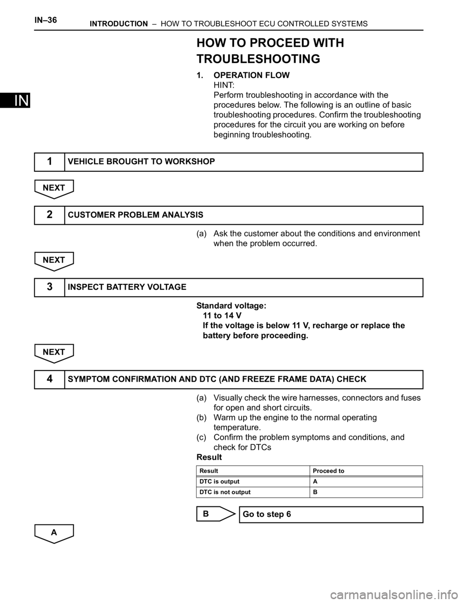
IN–36INTRODUCTION – HOW TO TROUBLESHOOT ECU CONTROLLED SYSTEMS
IN
HOW TO PROCEED WITH
TROUBLESHOOTING
1. OPERATION FLOW
HINT:
Perform troubleshooting in accordance with the
procedures below. The following is an outline of basic
troubleshooting procedures. Confirm the troubleshooting
procedures for the circuit you are working on before
beginning troubleshooting.
NEXT
(a) Ask the customer about the conditions and environment
when the problem occurred.
NEXT
Standard voltage:
11 to 14 V
If the voltage is below 11 V, recharge or replace the
battery before proceeding.
NEXT
(a) Visually check the wire harnesses, connectors and fuses
for open and short circuits.
(b) Warm up the engine to the normal operating
temperature.
(c) Confirm the problem symptoms and conditions, and
check for DTCs
Result
B
A
1VEHICLE BROUGHT TO WORKSHOP
2CUSTOMER PROBLEM ANALYSIS
3INSPECT BATTERY VOLTAGE
4SYMPTOM CONFIRMATION AND DTC (AND FREEZE FRAME DATA) CHECK
Result Proceed to
DTC is output A
DTC is not output B
Go to step 6
Page 66 of 3000
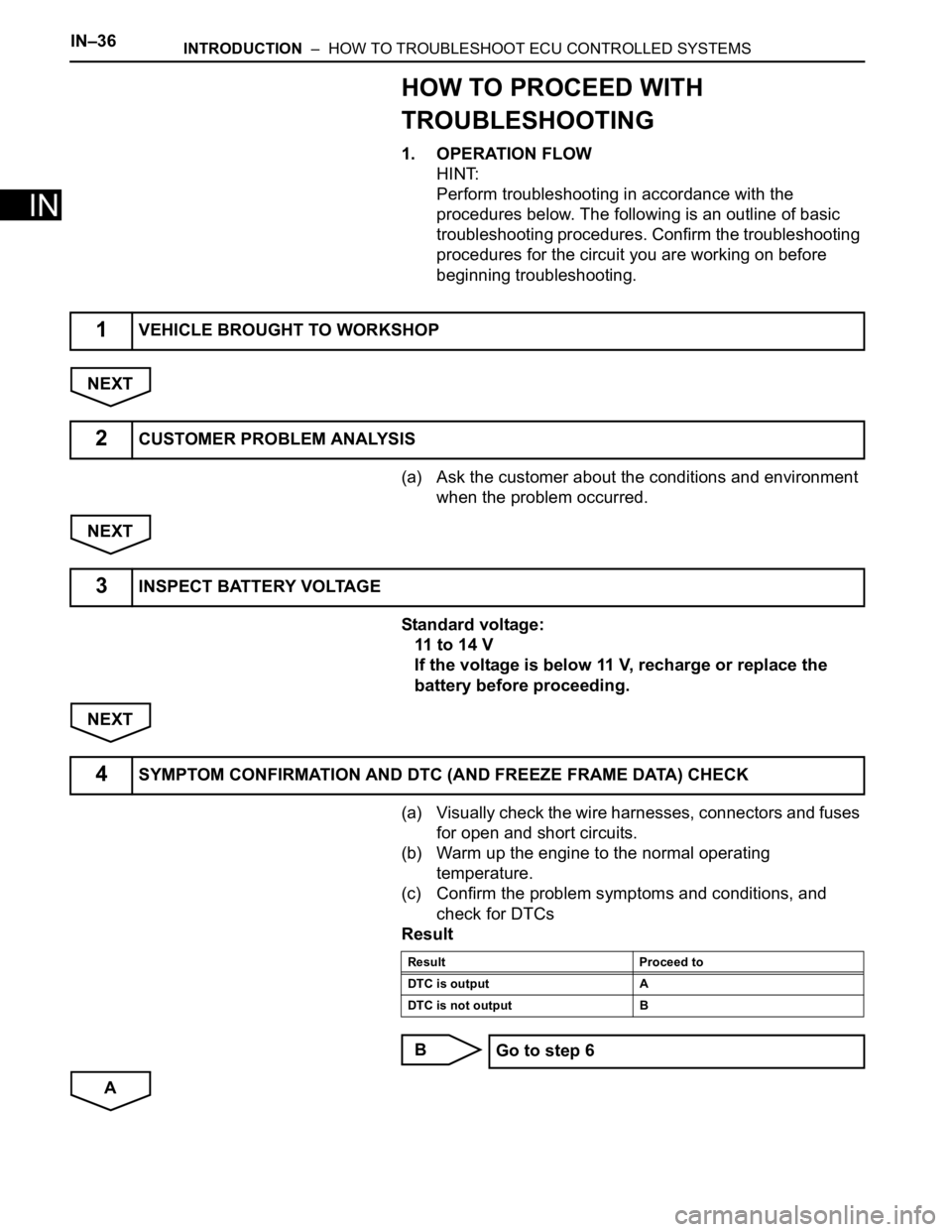
IN–36INTRODUCTION – HOW TO TROUBLESHOOT ECU CONTROLLED SYSTEMS
IN
HOW TO PROCEED WITH
TROUBLESHOOTING
1. OPERATION FLOW
HINT:
Perform troubleshooting in accordance with the
procedures below. The following is an outline of basic
troubleshooting procedures. Confirm the troubleshooting
procedures for the circuit you are working on before
beginning troubleshooting.
NEXT
(a) Ask the customer about the conditions and environment
when the problem occurred.
NEXT
Standard voltage:
11 to 14 V
If the voltage is below 11 V, recharge or replace the
battery before proceeding.
NEXT
(a) Visually check the wire harnesses, connectors and fuses
for open and short circuits.
(b) Warm up the engine to the normal operating
temperature.
(c) Confirm the problem symptoms and conditions, and
check for DTCs
Result
B
A
1VEHICLE BROUGHT TO WORKSHOP
2CUSTOMER PROBLEM ANALYSIS
3INSPECT BATTERY VOLTAGE
4SYMPTOM CONFIRMATION AND DTC (AND FREEZE FRAME DATA) CHECK
Result Proceed to
DTC is output A
DTC is not output B
Go to step 6
Page 282 of 3000

WINDSHIELD / WINDOWGLASS – POWER WINDOW CONTROL SYSTEM (w/ Jam Protec-
tion Function)WS–7
WS
INITIALIZATION
NOTICE:
• Resetting the power window motor (initializing the
pulse sensor) is necessary when the battery terminal
is disconnected; when the master switch, wire
harness, power window regulator and power window
motor are replaced or removed/installed; or when the
fuses are replaced. AUTO operation function, jam
protection function and remote operation function via
the power window master switch do not operate
without resetting.
• If the AUTO switch (driver side switch) of the master
switch has been continuously operated for a long
time, the power window motor will stop so that no
additional load can be applied to the motor.
Continuing to operate the switch even after the motor
has stopped will cause the switch to blink while
restricting the AUTO UP/DOWN function and the
remote UP/DOWN function. If this happens, reset the
motor again after several minutes have passed.
• Whenever disconnecting the battery terminal, reset all
the other systems besides the power window control
system.
1. RESET POWER WINDOW REGULATOR MOTOR
(DRIVER SIDE)
(a) Turn the ignition switch ON.
(b) Halfway open the power window by pressing the
power window switch.
(c) Fully pull up the switch until the power window is
fully closed and continue to hold the switch for
approx. 1 second after the power window is fully
closed.
(d) Check that the AUTO UP/DOWN function operates
normally.
If the AUTO UP/DOWN function operates normally,
reset operations have been completed at this time.
If not normal, follow steps below.
(1) Disconnect the negative battery terminal for 10
seconds.
(2) Connect the battery terminal.
(3) Perform the above steps (a) to (d) again.
HINT:
If operation is normal, reset operations have
been completed at this time. If not normal, follow
steps (4) to (7).
(4) Turn the ignition switch ON.
(5) Halfway open the power window by pressing the
power window switch.
(6) Fully pull up the switch until the power window is
fully closed and continue to hold the switch for
approx. 12 seconds after the power window is
fully closed.
(7) Check that the AUTO UP/DOWN function
operates normally.
Page 363 of 3000
2GR-FE ENGINE CONTROL SYSTEM – SFI SYSTEMES–45
ES
DTC CHECK / CLEAR
NOTICE:
All the stored DTCs and freeze frame data are erased if:
1) the ECM is changed from normal mode to check mode
or vice versa; or 2) the ignition switch is turned from ON
to ACC or off while in check mode.
Before changing modes, always check and make a note
of any DTCs and freeze frame data.
HINT:
• DTCs which are stored in the ECM can be displayed on an
intelligent tester. An intelligent tester can display current
and pending DTCs.
• Some DTCs are not set if the ECM does not detect the
same malfunction again during the second consecutive
driving cycle. However, such malfunctions, detected on
only one occasion, are stored as pending DTCs.
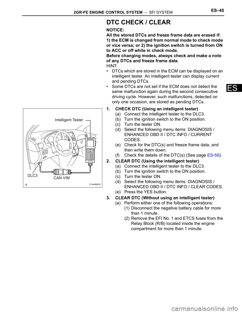
1. CHECK DTC (Using an intelligent tester)
(a) Connect the intelligent tester to the DLC3.
(b) Turn the ignition switch to the ON position.
(c) Turn the tester ON.
(d) Select the following menu items: DIAGNOSIS /
ENHANCED OBD II / DTC INFO / CURRENT
CODES.
(e) Check for the DTC(s) and freeze frame data, and
then write them down.
(f) Check the details of the DTC(s) (See page ES-56).
2. CLEAR DTC (Using the intelligent tester)
(a) Connect the intelligent tester to the DLC3.
(b) Turn the ignition switch to the ON position.
(c) Turn the tester ON.
(d) Select the following menu items: DIAGNOSIS /
ENHANCED OBD II / DTC INFO / CLEAR CODES.
(e) Press the YES button.
3. CLEAR DTC (Without using an intelligent tester)
(a) Perform either one of the following operations:
(1) Disconnect the negative battery cable for more
than 1 minute.
(2) Remove the EFI No. 1 and ETCS fuses from the
Relay Block (R/B) located inside the engine
compartment for more than 1 minute.
E144486E01
Page 827 of 3000
2GR-FE ENGINE CONTROL SYSTEM – SFI SYSTEMES–45
ES
DTC CHECK / CLEAR
NOTICE:
All the stored DTCs and freeze frame data are erased if:
1) the ECM is changed from normal mode to check mode
or vice versa; or 2) the ignition switch is turned from ON
to ACC or off while in check mode.
Before changing modes, always check and make a note
of any DTCs and freeze frame data.
HINT:
• DTCs which are stored in the ECM can be displayed on an
intelligent tester. An intelligent tester can display current
and pending DTCs.
• Some DTCs are not set if the ECM does not detect the
same malfunction again during the second consecutive
driving cycle. However, such malfunctions, detected on
only one occasion, are stored as pending DTCs.
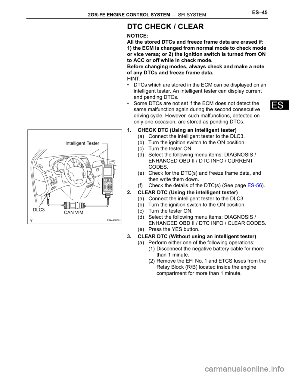
1. CHECK DTC (Using an intelligent tester)
(a) Connect the intelligent tester to the DLC3.
(b) Turn the ignition switch to the ON position.
(c) Turn the tester ON.
(d) Select the following menu items: DIAGNOSIS /
ENHANCED OBD II / DTC INFO / CURRENT
CODES.
(e) Check for the DTC(s) and freeze frame data, and
then write them down.
(f) Check the details of the DTC(s) (See page ES-56).
2. CLEAR DTC (Using the intelligent tester)
(a) Connect the intelligent tester to the DLC3.
(b) Turn the ignition switch to the ON position.
(c) Turn the tester ON.
(d) Select the following menu items: DIAGNOSIS /
ENHANCED OBD II / DTC INFO / CLEAR CODES.
(e) Press the YES button.
3. CLEAR DTC (Without using an intelligent tester)
(a) Perform either one of the following operations:
(1) Disconnect the negative battery cable for more
than 1 minute.
(2) Remove the EFI No. 1 and ETCS fuses from the
Relay Block (R/B) located inside the engine
compartment for more than 1 minute.
E144486E01
Page 1341 of 3000
CH–62GR-FE CHARGING – CHARGING SYSTEM
CH
ON-VEHICLE INSPECTION
1. CHECK BATTERY ELECTROLYTE LEVEL
(a) Check the electrolyte level.
(1) If the electrolyte level is low, replace the battery
(or add distilled water) and check the charging
system.
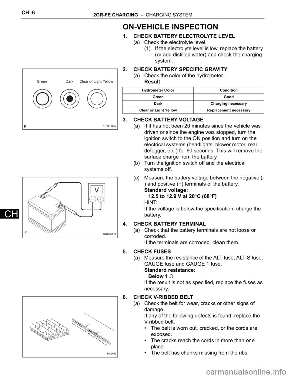
2. CHECK BATTERY SPECIFIC GRAVITY
(a) Check the color of the hydrometer.
Result
3. CHECK BATTERY VOLTAGE
(a) If it has not been 20 minutes since the vehicle was
driven or since the engine was stopped, turn the
ignition switch to the ON position and turn on the
electrical systems (headlights, blower motor, rear
defogger, etc.) for 60 seconds. This will remove the
surface charge from the battery.
(b) Turn the ignition switch off and the electrical
systems off.
(c) Measure the battery voltage between the negative (-
) and positive (+) terminals of the battery.
Standard voltage:
12.5 to 12.9 V at 20
C (68F)
HINT:
If the voltage is below the specification, charge the
battery.
4. CHECK BATTERY TERMINAL
(a) Check that the battery terminals are not loose or
corroded.
If the terminals are corroded, clean them.
5. CHECK FUSES
(a) Measure the resistance of the ALT fuse, ALT-S fuse,
GAUGE fuse and GAUGE 1 fuse.
Standard resistance:
Below 1
If the result is not as specified, replace the fuses as
necessary.
6. CHECK V-RIBBED BELT
(a) Check the belt for wear, cracks or other signs of
damage.
If any of the following defects is found, replace the
V-ribbed belt.
• The belt is worn out, cracked, or the cords are
exposed.
• The cracks reach the cords in more than one
place.
• The belt has chunks missing from the ribs.
A115815E02
Hydrometer Color Condition
Green Good
Dark Charging necessary
Clear or Light Yellow Replacement necessary
A081052E01
B000543
Page 1346 of 3000
CH–62GR-FE CHARGING – CHARGING SYSTEM
CH
ON-VEHICLE INSPECTION
1. CHECK BATTERY ELECTROLYTE LEVEL
(a) Check the electrolyte level.
(1) If the electrolyte level is low, replace the battery
(or add distilled water) and check the charging
system.
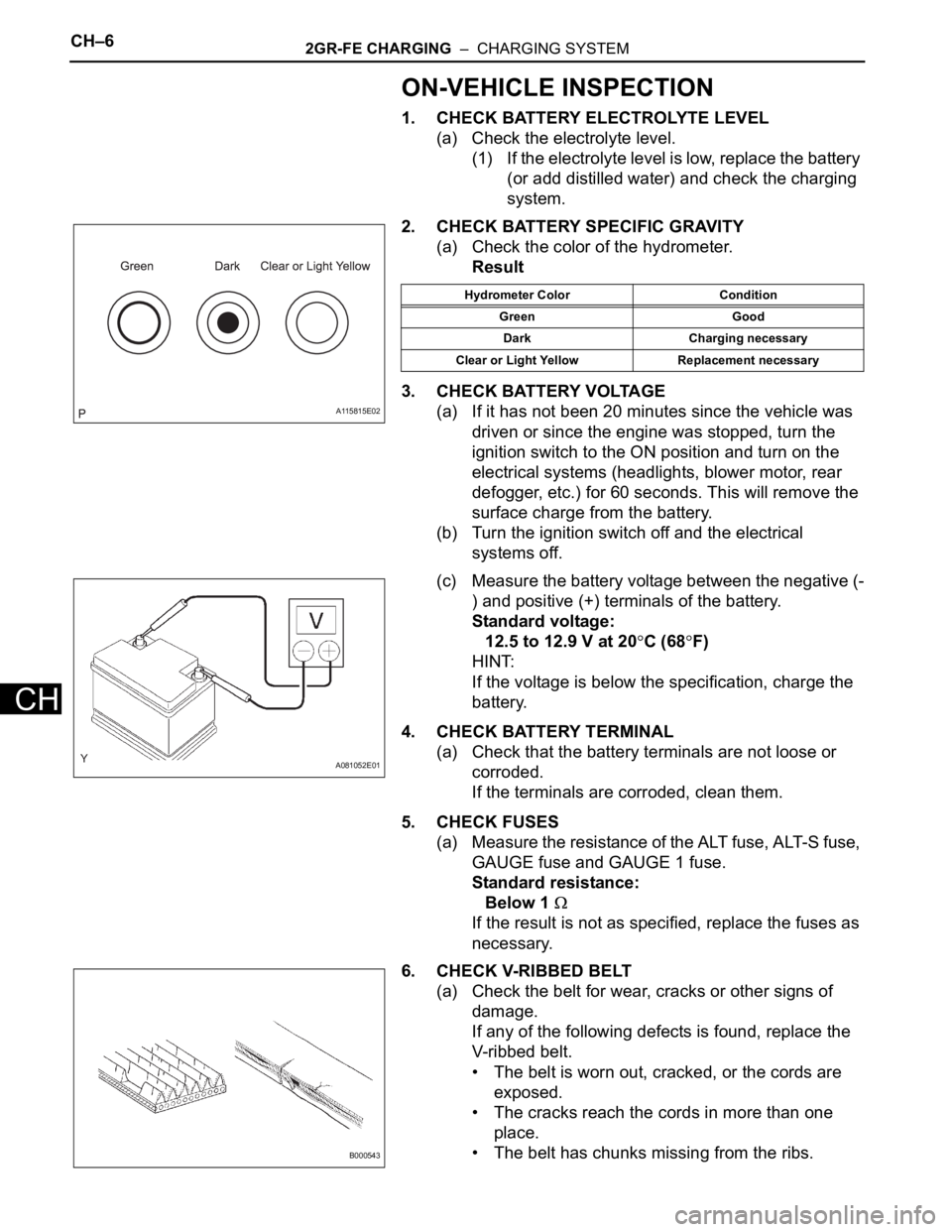
2. CHECK BATTERY SPECIFIC GRAVITY
(a) Check the color of the hydrometer.
Result
3. CHECK BATTERY VOLTAGE
(a) If it has not been 20 minutes since the vehicle was
driven or since the engine was stopped, turn the
ignition switch to the ON position and turn on the
electrical systems (headlights, blower motor, rear
defogger, etc.) for 60 seconds. This will remove the
surface charge from the battery.
(b) Turn the ignition switch off and the electrical
systems off.
(c) Measure the battery voltage between the negative (-
) and positive (+) terminals of the battery.
Standard voltage:
12.5 to 12.9 V at 20
C (68F)
HINT:
If the voltage is below the specification, charge the
battery.
4. CHECK BATTERY TERMINAL
(a) Check that the battery terminals are not loose or
corroded.
If the terminals are corroded, clean them.
5. CHECK FUSES
(a) Measure the resistance of the ALT fuse, ALT-S fuse,
GAUGE fuse and GAUGE 1 fuse.
Standard resistance:
Below 1
If the result is not as specified, replace the fuses as
necessary.
6. CHECK V-RIBBED BELT
(a) Check the belt for wear, cracks or other signs of
damage.
If any of the following defects is found, replace the
V-ribbed belt.
• The belt is worn out, cracked, or the cords are
exposed.
• The cracks reach the cords in more than one
place.
• The belt has chunks missing from the ribs.
A115815E02
Hydrometer Color Condition
Green Good
Dark Charging necessary
Clear or Light Yellow Replacement necessary
A081052E01
B000543
Page 1403 of 3000

U151E AUTOMATIC TRANSAXLE – AUTOMATIC TRANSAXLE SYSTEMAX–33
AX
(b) When not using the OBD II scan tool or intelligent
tester: Clearing the DTCs.
(1) Disconnect the battery terminal or remove the
EFI and ETCS fuses from the engine room J/B
for 60 seconds or more. However, if you
disconnect the battery terminal, perform do the
"INITIALIZE" procedure.