2007 TOYOTA SIENNA brake light switch
[x] Cancel search: brake light switchPage 180 of 3000
BC–4BRAKE CONTROL – ANTI-LOCK BRAKE SYSTEM
BC
TEST MODE PROCEDURE
1. SPEED SENSOR SIGNAL CHECK (WHEN USING SST
CHECK WIRE):
HINT:
• If the ignition switch is turned from the ON to the ACC
or LOCK position during Test Mode, the DTCs of the
signal check function will be erased.
(a) Turn the ignition switch off.
(b) Check that the steering wheel is in the straight-
ahead position and move the shift lever to the P
position (Automatic Transmission) or apply the
parking brake (Manual Transmission).
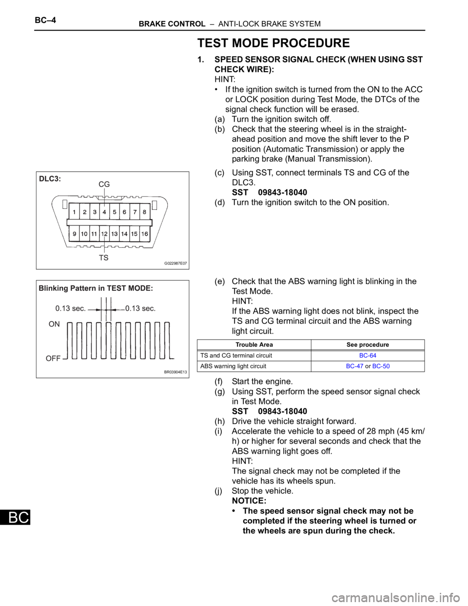
(c) Using SST, connect terminals TS and CG of the
DLC3.
SST 09843-18040
(d) Turn the ignition switch to the ON position.
(e) Check that the ABS warning light is blinking in the
Test Mode.
HINT:
If the ABS warning light does not blink, inspect the
TS and CG terminal circuit and the ABS warning
light circuit.
(f) Start the engine.
(g) Using SST, perform the speed sensor signal check
in Test Mode.
SST 09843-18040
(h) Drive the vehicle straight forward.
(i) Accelerate the vehicle to a speed of 28 mph (45 km/
h) or higher for several seconds and check that the
ABS warning light goes off.
HINT:
The signal check may not be completed if the
vehicle has its wheels spun.
(j) Stop the vehicle.
NOTICE:
• The speed sensor signal check may not be
completed if the steering wheel is turned or
the wheels are spun during the check.
G022987E07
BR03904E13
Trouble Area See procedure
TS and CG terminal circuitBC-64
ABS warning light circuitBC-47 or BC-50
Page 181 of 3000
BRAKE CONTROL – ANTI-LOCK BRAKE SYSTEMBC–5
BC
• After the ABS warning light goes off and if
vehicle speed exceeds 50 mph (80 km/h), the
signal check code will be stored again.
Decelerate or stop the vehicle before the
speed reaches 50 mph (80 km/h).
• If the signal check has not been completed,
the ABS warning light blinks while driving
and the ABS system does not operate.
HINT:
When the signal check has been completed, the
ABS warning light goes off while driving and blinks
in the Test Mode pattern while stationary.
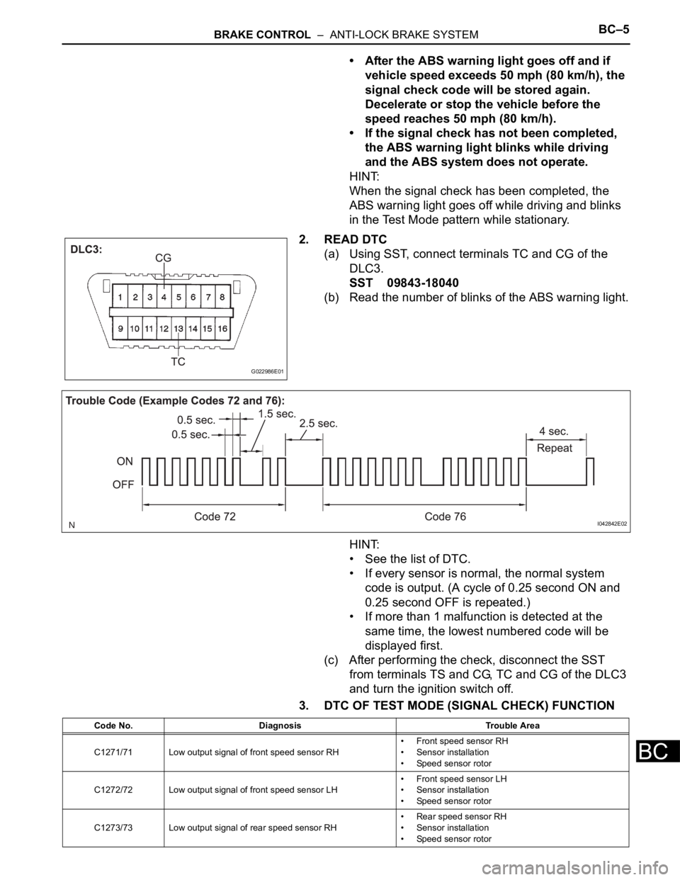
2. READ DTC
(a) Using SST, connect terminals TC and CG of the
DLC3.
SST 09843-18040
(b) Read the number of blinks of the ABS warning light.
HINT:
• See the list of DTC.
• If every sensor is normal, the normal system
code is output. (A cycle of 0.25 second ON and
0.25 second OFF is repeated.)
• If more than 1 malfunction is detected at the
same time, the lowest numbered code will be
displayed first.
(c) After performing the check, disconnect the SST
from terminals TS and CG, TC and CG of the DLC3
and turn the ignition switch off.
3. DTC OF TEST MODE (SIGNAL CHECK) FUNCTION
G022986E01
I042842E02
Code No. Diagnosis Trouble Area
C1271/71 Low output signal of front speed sensor RH• Front speed sensor RH
• Sensor installation
• Speed sensor rotor
C1272/72 Low output signal of front speed sensor LH• Front speed sensor LH
• Sensor installation
• Speed sensor rotor
C1273/73 Low output signal of rear speed sensor RH• Rear speed sensor RH
• Sensor installation
• Speed sensor rotor
Page 185 of 3000
BRAKE – BRAKE PEDALBR–11
BR
REMOVAL
1. SEPARATE BATTERY NEGATIVE TERMINAL
2. REMOVE FRONT DOOR SCUFF PLATE LH
3. REMOVE COWL SIDE TRIM BOARD LH
4. REMOVE INSTRUMENT PANEL FINISH PANEL SUB-
ASSEMBLY LOWER LH
(a) Remove the 2 bolts and instrument panel finish
panel sub-assembly lower LH.
5. REMOVE INSTRUMENT PANEL SAFETY PAD
INSERT SUB-ASSEMBLY NO. 1
(a) Remove the 4 bolts and instrument panel safety pad
insert sub-assembly No. 1.
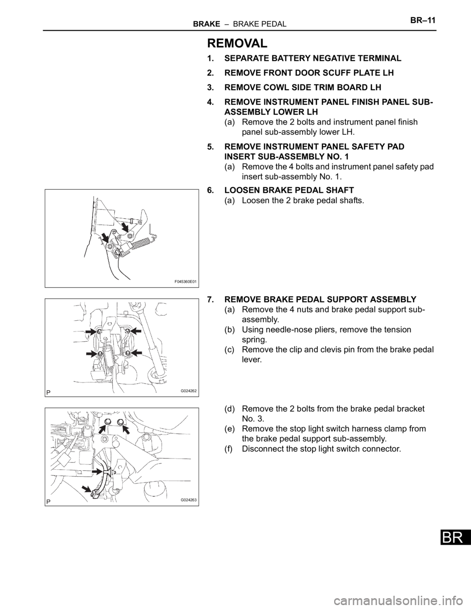
6. LOOSEN BRAKE PEDAL SHAFT
(a) Loosen the 2 brake pedal shafts.
7. REMOVE BRAKE PEDAL SUPPORT ASSEMBLY
(a) Remove the 4 nuts and brake pedal support sub-
assembly.
(b) Using needle-nose pliers, remove the tension
spring.
(c) Remove the clip and clevis pin from the brake pedal
lever.
(d) Remove the 2 bolts from the brake pedal bracket
No. 3.
(e) Remove the stop light switch harness clamp from
the brake pedal support sub-assembly.
(f) Disconnect the stop light switch connector.
F045360E01
G024262
G024263
Page 186 of 3000
BR–12BRAKE – BRAKE PEDAL
BR
DISASSEMBLY
1. REMOVE STOP LIGHT SWITCH ASSEMBLY
(a) Turn the stop light switch assembly
counterclockwise and remove the stop light switch
assembly.
(b) Remove the stop light switch mounting adjuster
from the brake pedal support sub-assembly.
2. REMOVE STOP LIGHT SWITCH CUSHION
(a) Remove the stop light switch cushion from the brake
pedal sub-assembly.
3. REMOVE BRAKE PEDAL
(a) Remove the 2 brake pedal shafts, 2 nuts and brake
pedal from the brake pedal support sub-assembly.
4. REMOVE BRAKE PEDAL BUSH
(a) Remove the 4 brake pedal bushes from the brake
pedal.
5. REMOVE BRAKE PEDAL SHAFT COLLAR
(a) Remove the 2 brake pedal shaft collars from the
brake pedal.
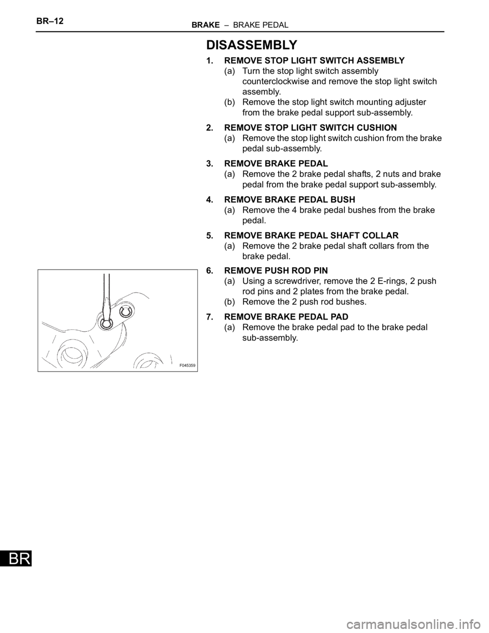
6. REMOVE PUSH ROD PIN
(a) Using a screwdriver, remove the 2 E-rings, 2 push
rod pins and 2 plates from the brake pedal.
(b) Remove the 2 push rod bushes.
7. REMOVE BRAKE PEDAL PAD
(a) Remove the brake pedal pad to the brake pedal
sub-assembly.
F045359
Page 382 of 3000
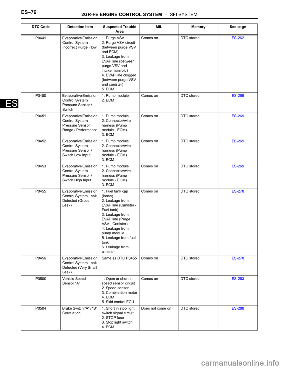
ES–762GR-FE ENGINE CONTROL SYSTEM – SFI SYSTEM
ES
P0441 Evaporative Emission
Control System
Incorrect Purge Flow1. Purge VSV
2. Purge VSV circuit
(between purge VSV
and ECM)
3. Leakage from
EVAP line (between
purge VSV and
intake manifold)
4. EVAP line clogged
(between purge VSV
and canister)
5. ECMComes on DTC storedES-262
P0450 Evaporative Emission
Control System
Pressure Sensor /
Switch1. Pump module
2. ECMComes on DTC storedES-269
P0451 Evaporative Emission
Control System
Pressure Sensor
Range / Performance1. Pump module
2. Connector/wire
harness (Pump
module - ECM)
3. ECMComes on DTC storedES-269
P0452 Evaporative Emission
Control System
Pressure Sensor /
Switch Low Input1. Pump module
2. Connector/wire
harness (Pump
module - ECM)
3. ECMComes on DTC storedES-269
P0453 Evaporative Emission
Control System
Pressure Sensor /
Switch High Input1. Pump module
2. Connector/wire
harness (Pump
module - ECM)
3. ECMComes on DTC storedES-269
P0455 Evaporative Emission
Control System Leak
Detected (Gross
Leak)1. Fuel tank cap
(loose)
2. Leakage from
EVAP line (Canister -
Fuel tank)
3. Leakage from
EVAP line (Purge
VSV - Canister)
4. Leakage from
pump module
5. Leakage from fuel
tank
6. Leakage from
canisterComes on DTC storedES-278
P0456 Evaporative Emission
Control System Leak
Detected (Very Small
Leak)Same as DTC P0455 Comes on DTC storedES-278
P0500 Vehicle Speed
Sensor "A"1. Open or short in
speed sensor circuit
2. Speed sensor
3. Combination meter
4. ECM
5. Skid control ECUComes on DTC storedES-283
P0504 Brake Switch "A" / "B"
Correlation1. Short in stop light
switch signal circuit
2. STOP fuse
3. Stop light switch
4. ECMDoes not come on DTC storedES-288 DTC Code Detection Item Suspected Trouble
AreaMIL Memory See page
Page 384 of 3000
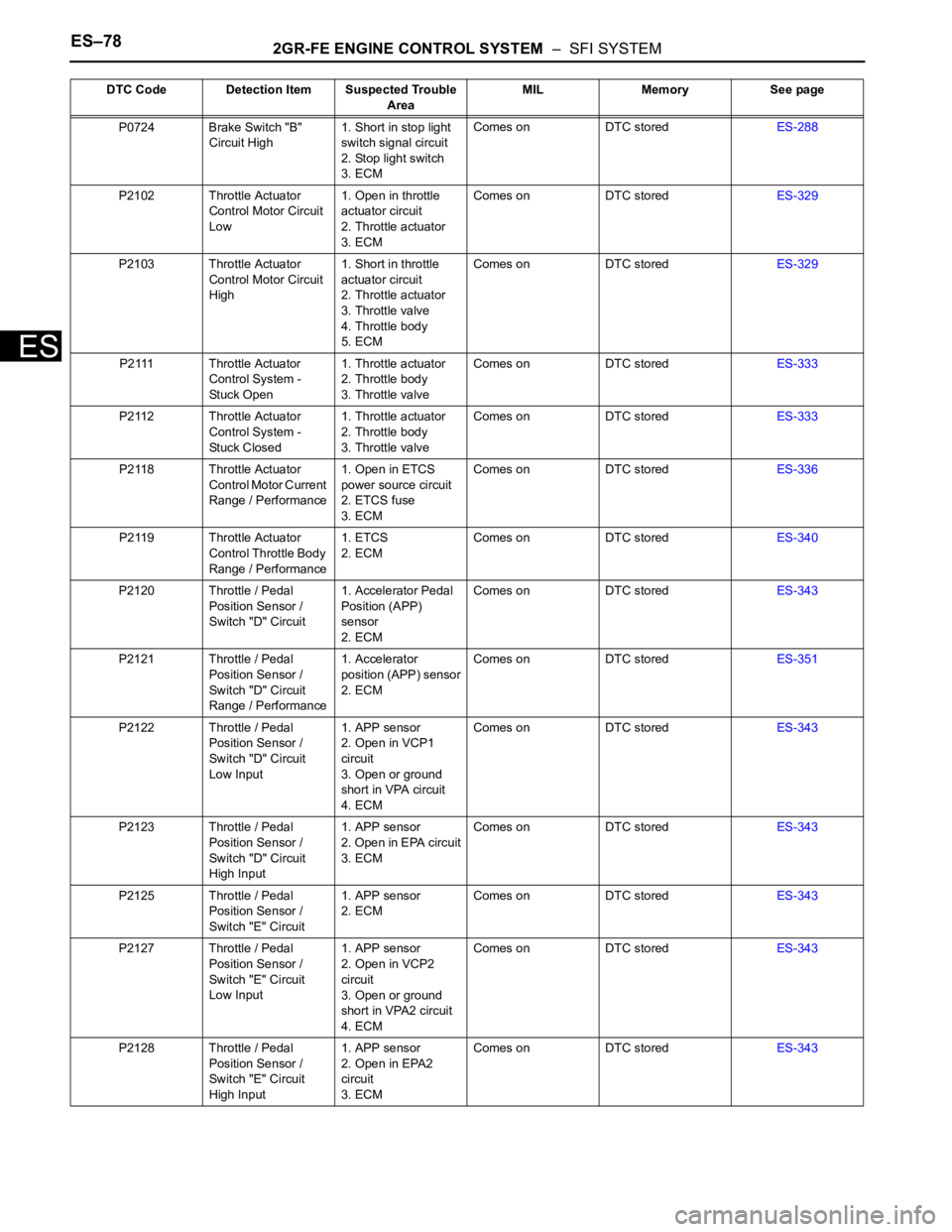
ES–782GR-FE ENGINE CONTROL SYSTEM – SFI SYSTEM
ES
P0724 Brake Switch "B"
Circuit High1. Short in stop light
switch signal circuit
2. Stop light switch
3. ECMComes on DTC storedES-288
P2102 Throttle Actuator
Control Motor Circuit
Low1. Open in throttle
actuator circuit
2. Throttle actuator
3. ECMComes on DTC storedES-329
P2103 Throttle Actuator
Control Motor Circuit
High1. Short in throttle
actuator circuit
2. Throttle actuator
3. Throttle valve
4. Throttle body
5. ECMComes on DTC storedES-329
P2111 Throttle Actuator
Control System -
Stuck Open1. Throttle actuator
2. Throttle body
3. Throttle valveComes on DTC storedES-333
P2112 Throttle Actuator
Control System -
Stuck Closed1. Throttle actuator
2. Throttle body
3. Throttle valveComes on DTC storedES-333
P2118 Throttle Actuator
Control Motor Current
Range / Performance1. Open in ETCS
power source circuit
2. ETCS fuse
3. ECMComes on DTC storedES-336
P2119 Throttle Actuator
Control Throttle Body
Range / Performance1. ETCS
2. ECMComes on DTC storedES-340
P2120 Throttle / Pedal
Position Sensor /
Switch "D" Circuit1. Accelerator Pedal
Position (APP)
sensor
2. ECMComes on DTC storedES-343
P2121 Throttle / Pedal
Position Sensor /
Switch "D" Circuit
Range / Performance1. Accelerator
position (APP) sensor
2. ECMComes on DTC storedES-351
P2122 Throttle / Pedal
Position Sensor /
Switch "D" Circuit
Low Input1. APP sensor
2. Open in VCP1
circuit
3. Open or ground
short in VPA circuit
4. ECMComes on DTC storedES-343
P2123 Throttle / Pedal
Position Sensor /
Switch "D" Circuit
High Input1. APP sensor
2. Open in EPA circuit
3. ECMComes on DTC storedES-343
P2125 Throttle / Pedal
Position Sensor /
Switch "E" Circuit1. APP sensor
2. ECMComes on DTC storedES-343
P2127 Throttle / Pedal
Position Sensor /
Switch "E" Circuit
Low Input1. APP sensor
2. Open in VCP2
circuit
3. Open or ground
short in VPA2 circuit
4. ECMComes on DTC storedES-343
P2128 Throttle / Pedal
Position Sensor /
Switch "E" Circuit
High Input1. APP sensor
2. Open in EPA2
circuit
3. ECMComes on DTC storedES-343 DTC Code Detection Item Suspected Trouble
AreaMIL Memory See page
Page 589 of 3000

ES–2962GR-FE ENGINE CONTROL SYSTEM – SFI SYSTEM
ES
DESCRIPTION
The stop light switch is a duplex system that transmits two signals: STP and ST1-. These two signals are
used by the ECM to monitor whether or not the brake system is working properly. If the signals, which
indicate the brake pedal is being depressed or released, are detected simultaneously, the ECM interprets
this as a malfunction in the stop light switch and sets the DTC.
HINT:
The normal conditions are as shown in the table below. The signals can be read using the intelligent
tester.
MONITOR DESCRIPTION
This DTC indicates that the stop light switch remains on. When the stop light switch remains ON during
"stop and go" driving, the ECM interprets this as a fault in the stop light switch and the MIL comes on and
the ECM stores the DTC. The vehicle must stop (less than 2 mph (3 km/h)) and go (19 mph (30 km/h) or
more) 5 times for two driving cycles in order to detect a malfunction.
MONITOR STRATEGY
TYPICAL ENABLING CONDITIONS
DTC P0504 Brake Switch "A" / "B" Correlation
DTC P0724 Brake Switch "B" Circuit High
Signals Brake Pedal Released In Transition Brake Pedal Depressed
STP OFF ON ON
ST1- ON ON OFF
DTC No. DTC Detection Condition Trouble Area
P0504Conditions (a), (b) and (c) continue for 0.5 seconds or
more (1 trip detection logic):
(a) Ignition switch in the ON position
(b) Brake pedal released
(c) STP signal OFF when ST1- signal OFF• Short in stop light switch signal circuit
• STOP fuse
• Stop light switch
•ECM
P0724The stop light switch remains ON even when the
vehicle is driven in a STOP (less than 2 mph (3 km/h))
and GO (19 mph (30 km/h) or more) fashion 5 times. (2
trip detection logic)• Short in stop light switch signal circuit
• Stop light switch
•ECM
Related DTCs P0724: Stop light switch/Rationality
Required sensors/Components Stop light switch, Vehicle speed sensor
Frequency of operation Continuous
Duration GO and STOP 5 times
MIL operation 2 driving cycles
Sequence of operation None
The monitor will run whenever this DTC is not present None
Ignition switch ON
Starter OFF
Battery voltage 8 V or more
GO (Vehicle speed is 18.65 mph (30 km/h) or more) Once
STOP (Vehicle speed is less than 1.86 mph (3 km/h)) Once
Page 590 of 3000
2GR-FE ENGINE CONTROL SYSTEM – SFI SYSTEMES–297
ES
TYPICAL MALFUNCTION THRESHOLDS
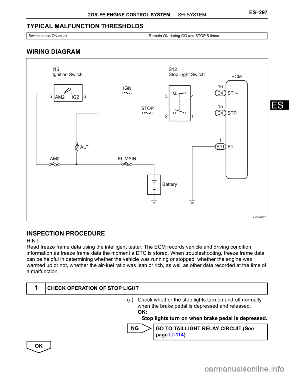
WIRING DIAGRAM
INSPECTION PROCEDURE
HINT:
Read freeze frame data using the intelligent tester. The ECM records vehicle and driving condition
information as freeze frame data the moment a DTC is stored. When troubleshooting, freeze frame data
can be helpful in determining whether the vehicle was running or stopped, whether the engine was
warmed up or not, whether the air-fuel ratio was lean or rich, as well as other data recorded at the time of
a malfunction.
(a) Check whether the stop lights turn on and off normally
when the brake pedal is depressed and released.
OK:
Stop lights turn on when brake pedal is depressed.
NG
OK
Switch status ON stuck Remain ON during GO and STOP 5 times
1CHECK OPERATION OF STOP LIGHT
A162496E02
GO TO TAILLIGHT RELAY CIRCUIT (See
page LI-114)