2007 TOYOTA SIENNA wiring
[x] Cancel search: wiringPage 34 of 3000
2GR-FE ENGINE MECHANICAL – ENGINE ASSEMBLYEM–35
EM
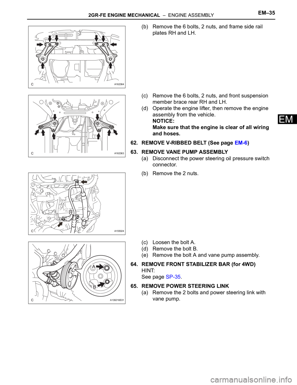
(b) Remove the 6 bolts, 2 nuts, and frame side rail
plates RH and LH.
(c) Remove the 6 bolts, 2 nuts, and front suspension
member brace rear RH and LH.
(d) Operate the engine lifter, then remove the engine
assembly from the vehicle.
NOTICE:
Make sure that the engine is clear of all wiring
and hoses.
62. REMOVE V-RIBBED BELT (See page EM-6)
63. REMOVE VANE PUMP ASSEMBLY
(a) Disconnect the power steering oil pressure switch
connector.
(b) Remove the 2 nuts.
(c) Loosen the bolt A.
(d) Remove the bolt B.
(e) Remove the bolt A and vane pump assembly.
64. REMOVE FRONT STABILIZER BAR (for 4WD)
HINT:
See page SP-35.
65. REMOVE POWER STEERING LINK
(a) Remove the 2 bolts and power steering link with
vane pump.
A162364
A162363
A155024
A139216E01
Page 55 of 3000
INTRODUCTION – HOW TO TROUBLESHOOT ECU CONTROLLED SYSTEMSIN–43
IN
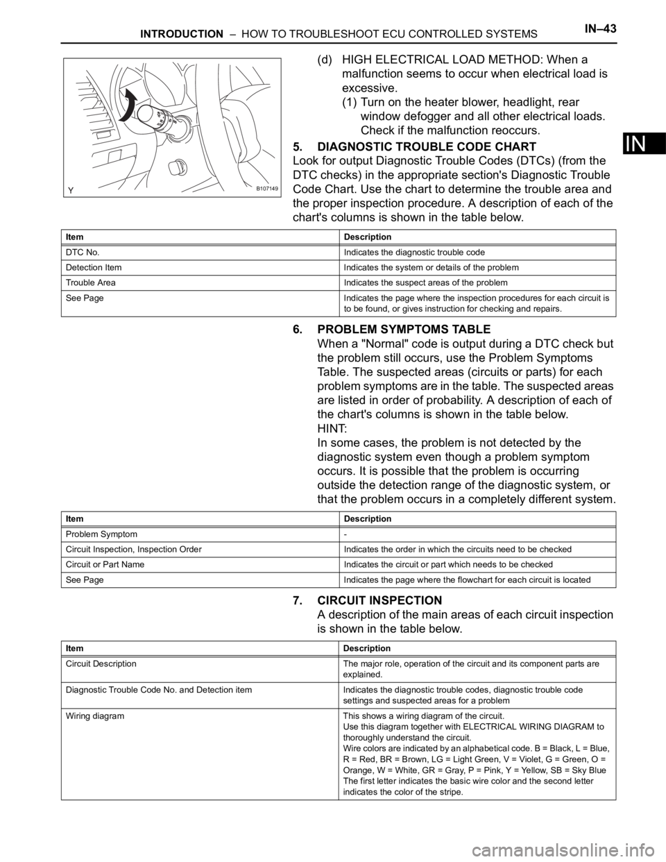
(d) HIGH ELECTRICAL LOAD METHOD: When a
malfunction seems to occur when electrical load is
excessive.
(1) Turn on the heater blower, headlight, rear
window defogger and all other electrical loads.
Check if the malfunction reoccurs.
5. DIAGNOSTIC TROUBLE CODE CHART
Look for output Diagnostic Trouble Codes (DTCs) (from the
DTC checks) in the appropriate section's Diagnostic Trouble
Code Chart. Use the chart to determine the trouble area and
the proper inspection procedure. A description of each of the
chart's columns is shown in the table below.
6. PROBLEM SYMPTOMS TABLE
When a "Normal" code is output during a DTC check but
the problem still occurs, use the Problem Symptoms
Table. The suspected areas (circuits or parts) for each
problem symptoms are in the table. The suspected areas
are listed in order of probability. A description of each of
the chart's columns is shown in the table below.
HINT:
In some cases, the problem is not detected by the
diagnostic system even though a problem symptom
occurs. It is possible that the problem is occurring
outside the detection range of the diagnostic system, or
that the problem occurs in a completely different system.
7. CIRCUIT INSPECTION
A description of the main areas of each circuit inspection
is shown in the table below.
B107149
Item Description
DTC No. Indicates the diagnostic trouble code
Detection Item Indicates the system or details of the problem
Trouble Area Indicates the suspect areas of the problem
See Page Indicates the page where the inspection procedures for each circuit is
to be found, or gives instruction for checking and repairs.
Item Description
Problem Symptom -
Circuit Inspection, Inspection Order Indicates the order in which the circuits need to be checked
Circuit or Part Name Indicates the circuit or part which needs to be checked
See Page Indicates the page where the flowchart for each circuit is located
Item Description
Circuit Description The major role, operation of the circuit and its component parts are
explained.
Diagnostic Trouble Code No. and Detection item Indicates the diagnostic trouble codes, diagnostic trouble code
settings and suspected areas for a problem
Wiring diagram This shows a wiring diagram of the circuit.
Use this diagram together with ELECTRICAL WIRING DIAGRAM to
thoroughly understand the circuit.
Wire colors are indicated by an alphabetical code. B = Black, L = Blue,
R = Red, BR = Brown, LG = Light Green, V = Violet, G = Green, O =
Orange, W = White, GR = Gray, P = Pink, Y = Yellow, SB = Sky Blue
The first letter indicates the basic wire color and the second letter
indicates the color of the stripe.
Page 62 of 3000
IN–32INTRODUCTION – HOW TO TROUBLESHOOT ECU CONTROLLED SYSTEMS
IN
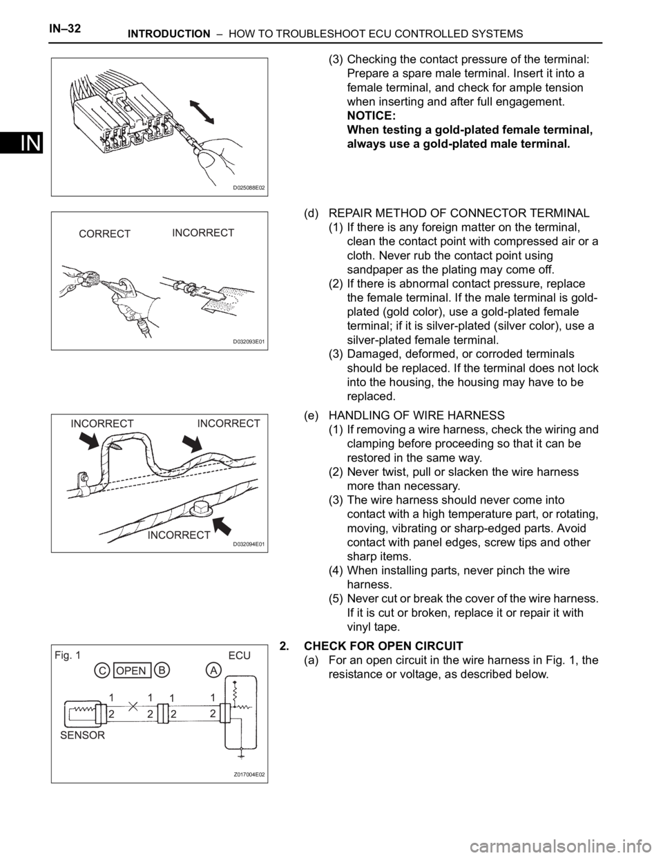
(3) Checking the contact pressure of the terminal:
Prepare a spare male terminal. Insert it into a
female terminal, and check for ample tension
when inserting and after full engagement.
NOTICE:
When testing a gold-plated female terminal,
always use a gold-plated male terminal.
(d) REPAIR METHOD OF CONNECTOR TERMINAL
(1) If there is any foreign matter on the terminal,
clean the contact point with compressed air or a
cloth. Never rub the contact point using
sandpaper as the plating may come off.
(2) If there is abnormal contact pressure, replace
the female terminal. If the male terminal is gold-
plated (gold color), use a gold-plated female
terminal; if it is silver-plated (silver color), use a
silver-plated female terminal.
(3) Damaged, deformed, or corroded terminals
should be replaced. If the terminal does not lock
into the housing, the housing may have to be
replaced.
(e) HANDLING OF WIRE HARNESS
(1) If removing a wire harness, check the wiring and
clamping before proceeding so that it can be
restored in the same way.
(2) Never twist, pull or slacken the wire harness
more than necessary.
(3) The wire harness should never come into
contact with a high temperature part, or rotating,
moving, vibrating or sharp-edged parts. Avoid
contact with panel edges, screw tips and other
sharp items.
(4) When installing parts, never pinch the wire
harness.
(5) Never cut or break the cover of the wire harness.
If it is cut or broken, replace it or repair it with
vinyl tape.
2. CHECK FOR OPEN CIRCUIT
(a) For an open circuit in the wire harness in Fig. 1, the
resistance or voltage, as described below.
D025088E02
D032093E01
D032094E01
Z017004E02
Page 73 of 3000
INTRODUCTION – HOW TO TROUBLESHOOT ECU CONTROLLED SYSTEMSIN–43
IN
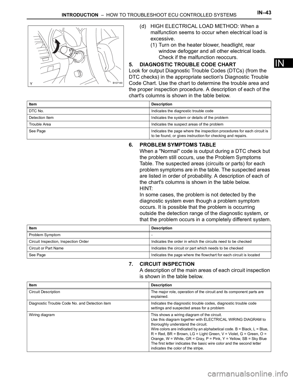
(d) HIGH ELECTRICAL LOAD METHOD: When a
malfunction seems to occur when electrical load is
excessive.
(1) Turn on the heater blower, headlight, rear
window defogger and all other electrical loads.
Check if the malfunction reoccurs.
5. DIAGNOSTIC TROUBLE CODE CHART
Look for output Diagnostic Trouble Codes (DTCs) (from the
DTC checks) in the appropriate section's Diagnostic Trouble
Code Chart. Use the chart to determine the trouble area and
the proper inspection procedure. A description of each of the
chart's columns is shown in the table below.
6. PROBLEM SYMPTOMS TABLE
When a "Normal" code is output during a DTC check but
the problem still occurs, use the Problem Symptoms
Table. The suspected areas (circuits or parts) for each
problem symptoms are in the table. The suspected areas
are listed in order of probability. A description of each of
the chart's columns is shown in the table below.
HINT:
In some cases, the problem is not detected by the
diagnostic system even though a problem symptom
occurs. It is possible that the problem is occurring
outside the detection range of the diagnostic system, or
that the problem occurs in a completely different system.
7. CIRCUIT INSPECTION
A description of the main areas of each circuit inspection
is shown in the table below.
B107149
Item Description
DTC No. Indicates the diagnostic trouble code
Detection Item Indicates the system or details of the problem
Trouble Area Indicates the suspect areas of the problem
See Page Indicates the page where the inspection procedures for each circuit is
to be found, or gives instruction for checking and repairs.
Item Description
Problem Symptom -
Circuit Inspection, Inspection Order Indicates the order in which the circuits need to be checked
Circuit or Part Name Indicates the circuit or part which needs to be checked
See Page Indicates the page where the flowchart for each circuit is located
Item Description
Circuit Description The major role, operation of the circuit and its component parts are
explained.
Diagnostic Trouble Code No. and Detection item Indicates the diagnostic trouble codes, diagnostic trouble code
settings and suspected areas for a problem
Wiring diagram This shows a wiring diagram of the circuit.
Use this diagram together with ELECTRICAL WIRING DIAGRAM to
thoroughly understand the circuit.
Wire colors are indicated by an alphabetical code. B = Black, L = Blue,
R = Red, BR = Brown, LG = Light Green, V = Violet, G = Green, O =
Orange, W = White, GR = Gray, P = Pink, Y = Yellow, SB = Sky Blue
The first letter indicates the basic wire color and the second letter
indicates the color of the stripe.
Page 81 of 3000

2GR-FE IGNITION – IGNITION COIL AND SPARK PLUGIG–7
IG
(3) Check the spark plug (See page EM-1).
Result
(4) Check the power supply to the ignition coil.
1. Turn the ignition switch to the ON position.
2. Check that there is battery voltage at the
ignition coil positive (+) terminal.
Result
(5) Measure the resistance of the crankshaft
position sensor (See page ES-514).
Result
(6) Check the IGT signal from the ECM (See page
ES-233)
Result
(e) Using a 16 mm (0.63 in.) plug wrench, install the
spark plugs.
Torque: 18 N*m (184 kgf*cm, 13 ft.*lbf)
(f) Connect the 6 fuel injector connectors.
(g) Install the ignition coil assembly (See page IG-10).
2. INSPECT SPARK PLUG
NOTICE:
• Never use a wire brush for cleaning.
• Never attempt to adjust the electrode gap on a
used spark plug.
(a) Check the electrode.
(1) Using a megohmmeter, measure the insulation
resistance.
Standard insulation resistance:
10 M
or higher
HINT:
• If the result is 10 M
or less, clean the plug
and measure the resistance again.
• If a megohmmeter is not available, perform
the following simple inspection instead.
(b) Alternative inspection method:
(1) Quickly accelerate the engine to 4000 rpm 5
times.
Result Proceed to
NG Replace spark plug
OK Go to next step
Result Proceed to
NGCheck wiring between ignition
switch and ignition coil
OK Go to next step
Result Proceed to
NG Replace crankshaft position sensor
OK Go to next step
Result Proceed to
NG Check ECM
OKRepair wiring between ignition coil
and ECM
I039522E10
Page 187 of 3000
PARKING BRAKE – PARKING BRAKE PEDALPB–5
PB
REMOVAL
1. DISCONNECT BATTERY NEGATIVE TERMINAL
2. REMOVE FRONT DOOR SCUFF PLATE LH
3. REMOVE COWL SIDE TRIM BOARD LH
4. REMOVE INSTRUMENT PANEL FINISH PANEL SUB-
ASSEMBLY LOWER LH (See page IP-6)
5. REMOVE REAR DOOR SCUFF PLATE RH
6. REMOVE REAR DOOR SCUFF PLATE LH
7. REMOVE FRONT SEAT ASSEMBLY LH
HINT:
• Manual Seat Type (See page SE-48)
• Power Seat Type (See page SE-58)
• Fold Flat Type (See page SE-40)
8. REMOVE REAR SEAT NO.1 ASSEMBLY
HINT:
• Captain Seat Type (See page SE-68)
• Center Seat Type (See page SE-77)
9. REMOVE REAR FLOOR SEAT LOCK COVER
10. REMOVE REAR FLOOR SEAT LOCK COVER
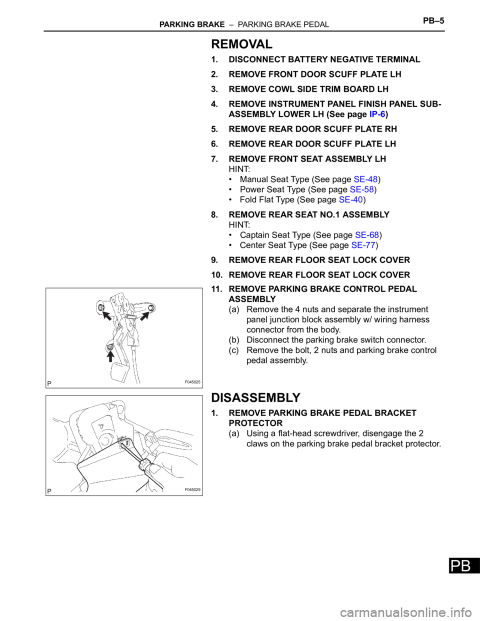
11. REMOVE PARKING BRAKE CONTROL PEDAL
ASSEMBLY
(a) Remove the 4 nuts and separate the instrument
panel junction block assembly w/ wiring harness
connector from the body.
(b) Disconnect the parking brake switch connector.
(c) Remove the bolt, 2 nuts and parking brake control
pedal assembly.
DISASSEMBLY
1. REMOVE PARKING BRAKE PEDAL BRACKET
PROTECTOR
(a) Using a flat-head screwdriver, disengage the 2
claws on the parking brake pedal bracket protector.
F045025
F045029
Page 233 of 3000
SUPPLEMENTAL RESTRAINT SYSTEM – SIDE AIRBAG SENSORRS–475
RS
INSTALLATION
HINT:
• Use the same procedures for the RH side and LH side.
• The procedures listed below are for the LH side.
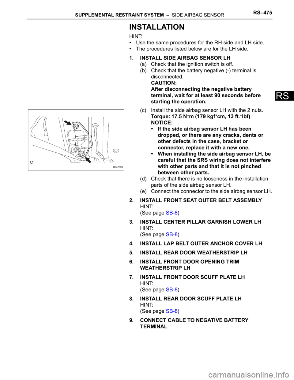
1. INSTALL SIDE AIRBAG SENSOR LH
(a) Check that the ignition switch is off.
(b) Check that the battery negative (-) terminal is
disconnected.
CAUTION:
After disconnecting the negative battery
terminal, wait for at least 90 seconds before
starting the operation.
(c) Install the side airbag sensor LH with the 2 nuts.
Torque: 17.5 N*m (179 kgf*cm, 13 ft.*lbf)
NOTICE:
• If the side airbag sensor LH has been
dropped, or there are any cracks, dents or
other defects in the case, bracket or
connector, replace it with a new one.
• When installing the side airbag sensor LH, be
careful that the SRS wiring does not interfere
with other parts and that it is not pinched
between other parts.
(d) Check that there is no looseness in the installation
parts of the side airbag sensor LH.
(e) Connect the connector to the side airbag sensor LH.
2. INSTALL FRONT SEAT OUTER BELT ASSEMBLY
HINT:
(See page SB-8)
3. INSTALL CENTER PILLAR GARNISH LOWER LH
HINT:
(See page SB-8)
4. INSTALL LAP BELT OUTER ANCHOR COVER LH
5. INSTALL REAR DOOR WEATHERSTRIP LH
6. INSTALL FRONT DOOR OPENING TRIM
WEATHERSTRIP LH
7. INSTALL FRONT DOOR SCUFF PLATE LH
HINT:
(See page SB-8)
8. INSTALL REAR DOOR SCUFF PLATE LH
HINT:
(See page SB-8)
9. CONNECT CABLE TO NEGATIVE BATTERY
TERMINAL
H042693
Page 322 of 3000
ES–2542GR-FE ENGINE CONTROL SYSTEM – SFI SYSTEM
ES
Exhaust Camshaft Sensor Range Check (Low voltage):
Exhaust Camshaft Sensor Range Check (High voltage):
WIRING DIAGRAM
Refer to DTC P0335 (See page ES-222).
INSPECTION PROCEDURE
HINT:
Read freeze frame data using the intelligent tester. The ECM records vehicle and driving condition
information as freeze frame data the moment a DTC is stored. When troubleshooting, freeze frame data
can be helpful in determining whether the vehicle was running or stopped, whether the engine was
warmed up or not, whether the air-fuel ratio was lean or rich, as well as other data recorded at the time of
a malfunction.
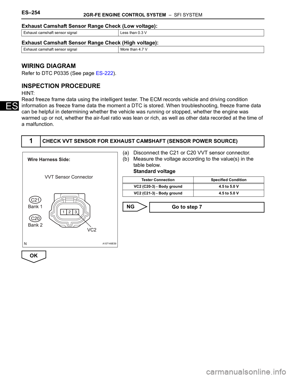
(a) Disconnect the C21 or C20 VVT sensor connector.
(b) Measure the voltage according to the value(s) in the
table below.
Standard voltage
NG
OK
Exhaust camshaft sensor signal Less than 0.3 V
Exhaust camshaft sensor signal More than 4.7 V
1CHECK VVT SENSOR FOR EXHAUST CAMSHAFT (SENSOR POWER SOURCE)
A107149E59
Tester Connection Specified Condition
VC2 (C20-3) - Body ground 4.5 to 5.0 V
VC2 (C21-3) - Body ground 4.5 to 5.0 V
Go to step 7