2007 TOYOTA SIENNA shift solenoid
[x] Cancel search: shift solenoidPage 16 of 3000

SS–30SERVICE SPECIFICATIONS – U151E AUTOMATIC TRANSAXLE
SS
TORQUE SPECIFICATIONS
Part Tightened N*m kgf*cm ft*lbf
Park/neutral position switch Nut 6.9 70 61 in.*lbf
Bolt 5.4 55 48 in.*lbf
Control shaft lever x Control shaft 13 130 9
Shift control cable x Control shaft lever 13 130 9
Transaxle housing x Engine block A bolt 64 653 47
B bolt 46 470 34
C bolt 43 439 32
Torque converter clutch x Drive plate 41 413 35
Flywheel housing under cover x Automatic transaxle 7.8 80 69 in.*lbf
Engine mounting bracket FR x Transaxle 64 653 47
Oil filler tube x Transaxle5.5 56 49 in.*lbf
Control cable bracket No. 1 x Transaxle 12 122 9
Control cable bracket No. 2 x Transaxle 12 122 9
Oil cooler tube clamp x Control cable bracket 5.5 56 49 in.*lbf
Oil cooler inlet tube x Transaxle27 275 20
Oil cooler outlet tube x Transaxle 27 275 20
Starter x Transaxle37 377 27
Starter wire x Starter9.8 100 87 in.*lbf
Wire harness x Transaxle13 133 10
Wire harness clamp x Transaxle8.4 86 74 in.*lbf
Speed sensor (NC) x Transaxle11 11 5 8
Speed sensor (NT) x Transaxle11 11 2 8
Air cleaner x Air cleaner hose5.0 51 44 in.*lbf
Drain plug x Oil pan49 500 36
Transmission wire x Transaxle5.4 55 48 in.*lbf
ATF temperature sensor x Valve body 6.6 67 58 in.*lbf
Oil pan x Transaxle7.8 80 69 in.*lbf
Solenoid valve x Valve body A B bolt 11 110 8
C D bolt 6.6 67 58 in.*lbf
Valve body x Transaxle11 11 0 8
Oil strainer x Valve body11 11 0 8
Floor shift assembly x Body21 214 15
Control cable x Body12 122 9
Engine mount bracket RR x Transfer stiffener plate RH 34 350 25
Oil cooler assembly x Body Nut
7.0 71 62 in.*lbf
bolt
Differential gear lube apply tube x Transaxle housing 9.8 100 87 in.*lbf
Front planetary gear lock nut
210 to 3502,141 to
3,569155 to 258
Brake apply tube clamp x Transaxle case 5.4 55 48 in.*lbf
Transaxle case No. 1 plug x Transaxle rear cover 7.4 75 65 in.*lbf
Transaxle rear cover x Transaxle case Bolt A 19 190 14
Other bolt 25 250 18
Pawl shaft clamp x Transaxle case 9.8 100 87 in.*lbf
Oil pump assembly x Transaxle case 22 226 16
Page 17 of 3000

SERVICE SPECIFICATIONS – U151E AUTOMATIC TRANSAXLESS–31
SS
Transaxle housing x Transaxle case Bolt A 22 225 16
Bolt B 29 300 22
Bolt C 29 295 21
Bolt D 22 226 16
Automatic transmission case plug x Transaxle housing 7.4 75 65 in.*lbf
Automatic transmission case plug x Transaxle case 7.4 75 65 in.*lbf
Parking lock pawl bracket x Transaxle case 20 205 15
Manual detent spring x Transaxle case Bolt A 20 205 15
Bolt B 12 120 9
Transmission wire x Transaxle housing 5.4 55 48 in.*lbf
Transmission valve body x Transaxle case 11 110 8
ATF temperature sensor clamp x Transmission valve body 6.6 67 58 in.*lbf
Valve body oil strainer assembly x Transmission valve body 11 1108
Automatic transaxle oil pan sub-assembly x Transaxle case 7.8 80 69 in.*lbf
Drain plug x Automatic transaxle oil pan sub-assembly 49 500 36
Speed sensor x Transaxle case11 11 5 8
Oil cooler tube union x Transaxle case Union 27 276 20
Elbow 27 276 20
Park/neutral start switch x nut6.9 70 61 in.*lbf
Park/neutral start switch x Bolt5.4 55 48 in.*lbf
Park/neutral start switch x Control shaft lever 13 130 9
Speedometer driven hole cover sub-assembly x Transaxle case 6.9 7061
Oil pump body x Stator shaft assembly 9.8 100 87 in.*lbf
Line pressure control solenoid assembly x Transmission valve body assembly 6.6 67 58 in.*lbf
Shift solenoid valve SL1 x Transmission valve body assembly 6.6 67 58 in.*lbf
Shift solenoid valve SL2 x Transmission valve body assembly 10.811 0 8
Shift solenoid valve SL3 x Transmission valve body assembly 6.6 67 58 in.*lbf
Shift solenoid valve S4 x Transmission valve body assembly 10.8 110 8
Shift solenoid valve DSL x Transmission valve body assembly 10.811 0 8
Front differential case x Front differential ring gear 95.1 970 70Part Tightened N*m kgf*cm ft*lbf
Page 214 of 3000

SERVICE SPECIFICATIONS – U151F AUTOMATIC TRANSAXLESS–37
SS
TORQUE SPECIFICATIONS
Part Tightened N*m kgf*cm ft*lbf
Park/neutral position switch Nut 6.9 70 61 in.*lbf
Bolt 5.4 55 48 in.*lbf
Control shaft lever x Control shaft 13 130 9
Shift control cable x Control shaft lever 13 130 9
Transaxle housing x Engine block A bolt 64 653 47
B bolt 46 470 34
C bolt 43 439 32
Torque converter clutch x Drive plate 41 413 30
Flywheel housing under cover x Automatic transaxle 7.8 80 69 in.*lbf
Engine mounting bracket FR x Transaxle 64 653 47
Oil filler tube x Transaxle5.5 56 49 in.*lbf
Control cable bracket No. 1 x Transaxle 12 122 9
Control cable bracket No. 2 x Transaxle 12 122 9
Oil cooler tube clamp x Control cable bracket 5.5 56 49 in.*lbf
Oil cooler inlet tube x Transaxle27 275 20
Oil cooler outlet tube x Transaxle 27 275 20
Starter x Transaxle37 377 27
Starter wire x Starter9.8 100 87 in.*lbf
Wire harness x Transaxle13 133 10
Wire harness clamp x Transaxle8.4 86 74 in.*lbf
Speed sensor (NC) x Transaxle11 11 5 8
Speed sensor (NT) x Transaxle11 11 2 8
Air cleaner x Air cleaner hose5.0 51 44 in.*lbf
Drain plug x Oil pan49 500 36
Transmission wire x Transaxle5.4 55 48 in.*lbf
ATF temperature sensor x Valve body 6.6 67 58 in.*lbf
Oil pan x Transaxle7.8 80 69 in.*lbf
Solenoid valve x Valve body A B bolt 11 110 8
C D bolt 6.6 67 58 in.*lbf
Valve body x Transaxle11 11 0 8
Oil strainer x Valve body11 11 0 8
Floor shift assembly x Body21 214 15
Control cable x Body12 122 9
Transfer x Transaxle69 700 51
Transfer x Transfer stiffener plate RH 34 350 25
Engine mount bracket RR x Transfer stiffener plate RH 34 350 25
Oil cooler assembly x Body Nut
7.0 71 62 in.*lbf
bolt
Differential gear lube apply tube x Transaxle housing 9.8 100 87 in.*lbf
Front planetary gear lock nut
210 to 3502,141 to
3,569155 to 258
Brake apply tube clamp x Transaxle case 5.4 55 48 in.*lbf
Transaxle case No. 1 plug x Transaxle rear cover 7.4 75 65 in.*lbf
Transaxle rear cover x Transaxle case Bolt A 19 190 14
Other bolt 25 250 18
Pawl shaft clamp x Transaxle case 9.8 100 87 in.*lbf
Oil pump assembly x Transaxle case 22 226 16
Page 215 of 3000

SS–38SERVICE SPECIFICATIONS – U151F AUTOMATIC TRANSAXLE
SS
Transaxle housing x Transaxle case Bolt A 22 225 16
Bolt B 29 300 22
Bolt C 29 295 21
Bolt D 22 226 16
Automatic transmission case plug x Transaxle housing 7.4 75 65 in.*lbf
Automatic transmission case plug x Transaxle case 7.4 75 65 in.*lbf
Parking lock pawl bracket x Transaxle case 20 205 15
Manual detent spring x Transaxle case Bolt A 20 205 15
Bolt B 12 120 9
Transmission wire x Transaxle housing 5.4 55 48 in.*lbf
Transmission valve body x Transaxle case 11 110 8
ATF temperature sensor clamp x Transmission valve body 6.6 67 58 in.*lbf
Valve body oil strainer assembly x Transmission valve body 11 1108
Automatic transaxle oil pan sub-assembly x Transaxle case 7.8 80 69 in.*lbf
Drain plug x Automatic transaxle oil pan sub-assembly 49 500 36
Speed sensor x Transaxle case11 11 5 8
Oil cooler tube union x Transaxle case Union 27 276 20
Elbow 27 276 20
Park/neutral start switch x nut6.9 70 61 in.*lbf
Park/neutral start switch x Bolt5.4 55 48 in.*lbf
Park/neutral start switch x Control shaft lever 13 130 9
Speedometer driven hole cover sub-assembly x Transaxle case 6.9 7061
Oil pump body x Stator shaft assembly 9.8 100 87 in.*lbf
Line pressure control solenoid assembly x Transmission valve body assembly 6.6 67 58 in.*lbf
Shift solenoid valve SL1 x Transmission valve body assembly 6.6 67 58 in.*lbf
Shift solenoid valve SL2 x Transmission valve body assembly 10.811 0 8
Shift solenoid valve SL3 x Transmission valve body assembly 6.6 67 58 in.*lbf
Shift solenoid valve S4 x Transmission valve body assembly 10.8 110 8
Shift solenoid valve DSL x Transmission valve body assembly 10.811 0 8
Front differential case x Front differential ring gear 95.1 970 70Part Tightened N*m kgf*cm ft*lbf
Page 1393 of 3000

AX–16U151E AUTOMATIC TRANSAXLE – AUTOMATIC TRANSAXLE SYSTEM
AX
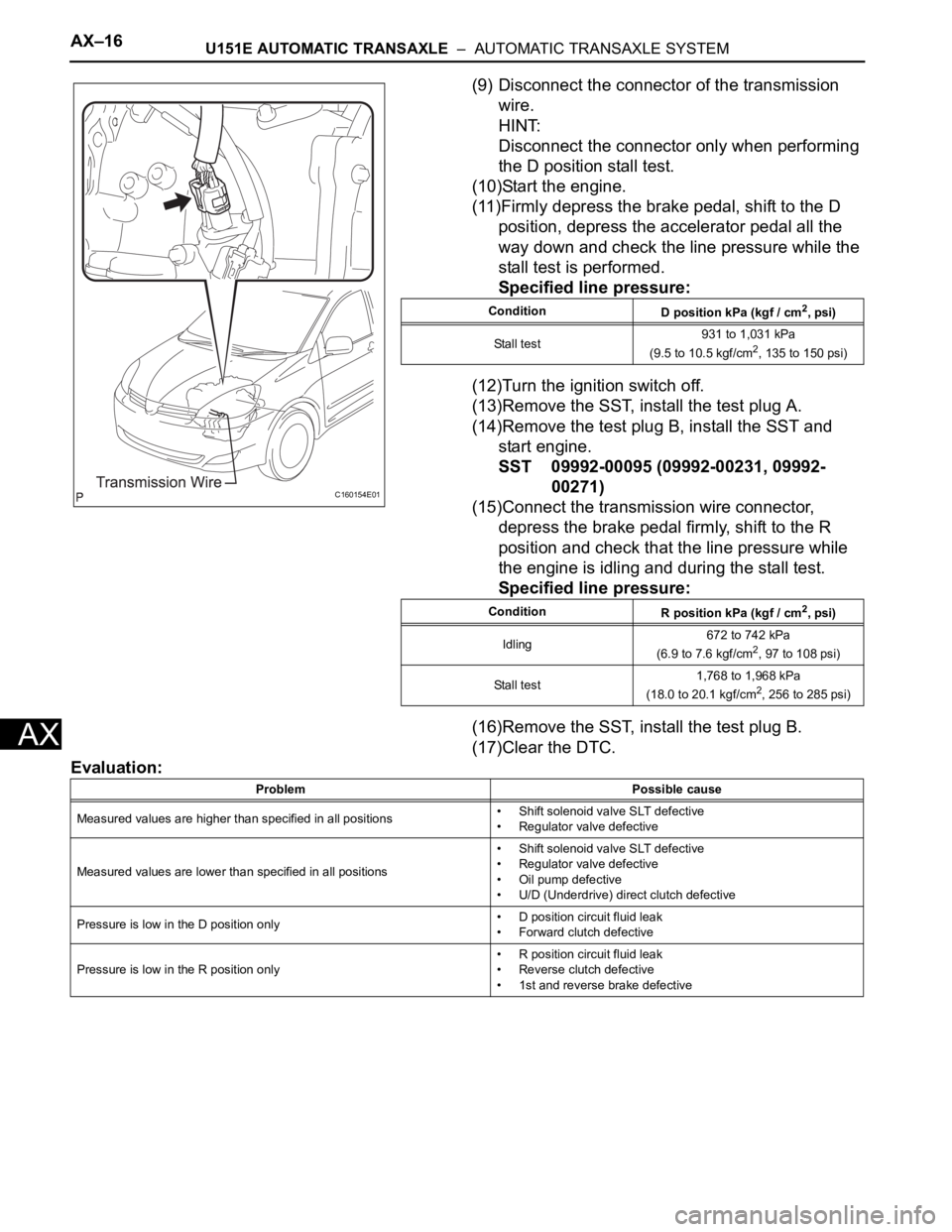
(9) Disconnect the connector of the transmission
wire.
HINT:
Disconnect the connector only when performing
the D position stall test.
(10)Start the engine.
(11)Firmly depress the brake pedal, shift to the D
position, depress the accelerator pedal all the
way down and check the line pressure while the
stall test is performed.
Specified line pressure:
(12)Turn the ignition switch off.
(13)Remove the SST, install the test plug A.
(14)Remove the test plug B, install the SST and
start engine.
SST 09992-00095 (09992-00231, 09992-
00271)
(15)Connect the transmission wire connector,
depress the brake pedal firmly, shift to the R
position and check that the line pressure while
the engine is idling and during the stall test.
Specified line pressure:
(16)Remove the SST, install the test plug B.
(17)Clear the DTC.
Evaluation:
C160154E01
Condition
D position kPa (kgf / cm2, psi)
Stall test931 to 1,031 kPa
(9.5 to 10.5 kgf/cm
2, 135 to 150 psi)
Condition
R position kPa (kgf / cm
2, psi)
Idling672 to 742 kPa
(6.9 to 7.6 kgf/cm
2, 97 to 108 psi)
Stall test1,768 to 1,968 kPa
(18.0 to 20.1 kgf/cm
2, 256 to 285 psi)
Problem Possible cause
Measured values are higher than specified in all positions• Shift solenoid valve SLT defective
• Regulator valve defective
Measured values are lower than specified in all positions• Shift solenoid valve SLT defective
• Regulator valve defective
• Oil pump defective
• U/D (Underdrive) direct clutch defective
Pressure is low in the D position only• D position circuit fluid leak
• Forward clutch defective
Pressure is low in the R position only• R position circuit fluid leak
• Reverse clutch defective
• 1st and reverse brake defective
Page 1399 of 3000

AX–22U151E AUTOMATIC TRANSAXLE – AUTOMATIC TRANSAXLE SYSTEM
AX
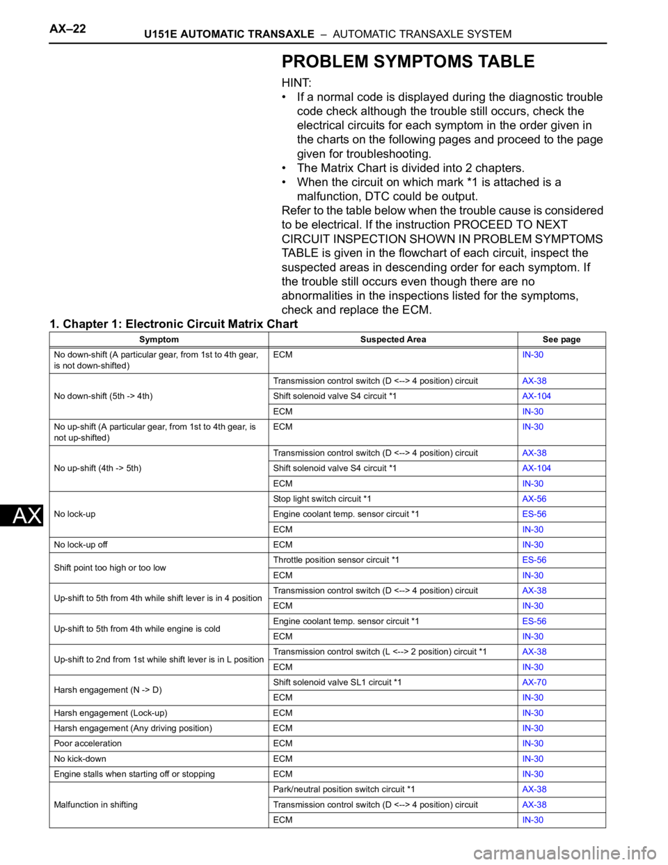
PROBLEM SYMPTOMS TABLE
HINT:
• If a normal code is displayed during the diagnostic trouble
code check although the trouble still occurs, check the
electrical circuits for each symptom in the order given in
the charts on the following pages and proceed to the page
given for troubleshooting.
• The Matrix Chart is divided into 2 chapters.
• When the circuit on which mark *1 is attached is a
malfunction, DTC could be output.
Refer to the table below when the trouble cause is considered
to be electrical. If the instruction PROCEED TO NEXT
CIRCUIT INSPECTION SHOWN IN PROBLEM SYMPTOMS
TABLE is given in the flowchart of each circuit, inspect the
suspected areas in descending order for each symptom. If
the trouble still occurs even though there are no
abnormalities in the inspections listed for the symptoms,
check and replace the ECM.
1. Chapter 1: Electronic Circuit Matrix Chart
Symptom Suspected Area See page
No down-shift (A particular gear, from 1st to 4th gear,
is not down-shifted)ECMIN-30
No down-shift (5th -> 4th)Transmission control switch (D <--> 4 position) circuitAX-38
Shift solenoid valve S4 circuit *1AX-104
ECMIN-30
No up-shift (A particular gear, from 1st to 4th gear, is
not up-shifted)ECMIN-30
No up-shift (4th -> 5th)Transmission control switch (D <--> 4 position) circuitAX-38
Shift solenoid valve S4 circuit *1AX-104
ECMIN-30
No lock-upStop light switch circuit *1AX-56
Engine coolant temp. sensor circuit *1ES-56
ECMIN-30
No lock-up off ECMIN-30
Shift point too high or too lowThrottle position sensor circuit *1ES-56
ECMIN-30
Up-shift to 5th from 4th while shift lever is in 4 positionTransmission control switch (D <--> 4 position) circuitAX-38
ECMIN-30
Up-shift to 5th from 4th while engine is coldEngine coolant temp. sensor circuit *1ES-56
ECMIN-30
Up-shift to 2nd from 1st while shift lever is in L positionTransmission control switch (L <--> 2 position) circuit *1AX-38
ECMIN-30
Harsh engagement (N -> D)Shift solenoid valve SL1 circuit *1AX-70
ECMIN-30
Harsh engagement (Lock-up) ECMIN-30
Harsh engagement (Any driving position) ECMIN-30
Poor acceleration ECMIN-30
No kick-down ECMIN-30
Engine stalls when starting off or stopping ECMIN-30
Malfunction in shiftingPark/neutral position switch circuit *1AX-38
Transmission control switch (D <--> 4 position) circuitAX-38
ECMIN-30
Page 1400 of 3000

U151E AUTOMATIC TRANSAXLE – AUTOMATIC TRANSAXLE SYSTEMAX–23
AX
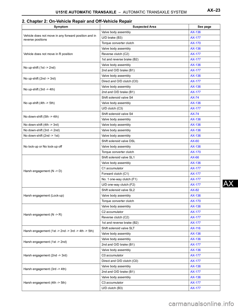
2. Chapter 2: On-Vehicle Repair and Off-Vehicle Repair
Symptom Suspected Area See page
Vehicle does not move in any forward position and in
reverse positionsValve body assemblyAX-136
U/D brake (B3)AX-177
Torque converter clutchAX-170
Vehicle does not move in R positionValve body assemblyAX-136
Reverse clutch (C2)AX-177
1st and reverse brake (B2)AX-177
No up-shift (1st -> 2nd)Valve body assemblyAX-136
2nd and O/D brake (B1)AX-177
No up-shift (2nd -> 3rd)Valve body assemblyAX-136
Direct and O/D clutch (C0)AX-177
No up-shift (3rd -> 4th)Valve body assemblyAX-136
2nd and O/D brake (B1)AX-177
No up-shift (4th -> 5th)Shift solenoid valve S4AX-74
Valve body assemblyAX-136
U/D clutch (C3)AX-177
No down-shift (5th -> 4th)Shift solenoid valve S4AX-74
Valve body assemblyAX-136
No down-shift (4th -> 3rd) Valve body assemblyAX-136
No down-shift (3rd -> 2nd) Valve body assemblyAX-136
No down-shift (2nd -> 1st) Valve body assemblyAX-136
No lock-up or No lock-up offShift solenoid valve DSLAX-60
Valve body assemblyAX-136
Torque converter clutchAX-170
Harsh engagement (N -> D)Shift solenoid valve SL1AX-66
Valve body assemblyAX-136
C1 accumulatorAX-177
Forward clutch (C1)AX-177
No. 1 one-way clutch (F1)AX-177
U/D one-way clutch (F2)AX-177
Harsh engagement (Lock-up)Shift solenoid valve SL2AX-82
Valve body assemblyAX-136
Torque converter clutchAX-170
Harsh engagement (N -> R)Valve body assemblyAX-136
C2 accumulatorAX-177
Reverse clutch (C2)AX-177
1st and reverse brake (B2)AX-177
Harsh engagement (1st -> 2nd -> 3rd -> 4th -> 5th)Shift solenoid valve SLTAX-116
Valve body assemblyAX-136
Harsh engagement (1st -> 2nd)Valve body assemblyAX-136
2nd and O/D brake (B1)AX-177
Harsh engagement (2nd -> 3rd)Valve body assemblyAX-136
C0 accumulatorAX-177
Direct and O/D clutch (C0)AX-177
Harsh engagement (3rd -> 4th)Valve body assemblyAX-136
2nd and O/D brake (B1)AX-177
Harsh engagement (4th -> 5th)Valve body assemblyAX-136
C3 accumulatorAX-177
U/D clutch (B3)AX-177
Page 1401 of 3000

AX–24U151E AUTOMATIC TRANSAXLE – AUTOMATIC TRANSAXLE SYSTEM
AX
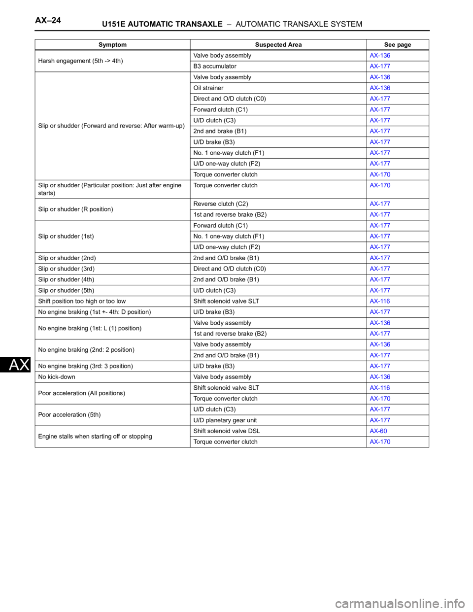
Harsh engagement (5th -> 4th)Valve body assemblyAX-136
B3 accumulatorAX-177
Slip or shudder (Forward and reverse: After warm-up)Valve body assemblyAX-136
Oil strainerAX-136
Direct and O/D clutch (C0)AX-177
Forward clutch (C1)AX-177
U/D clutch (C3)AX-177
2nd and brake (B1)AX-177
U/D brake (B3)AX-177
No. 1 one-way clutch (F1)AX-177
U/D one-way clutch (F2)AX-177
Torque converter clutchAX-170
Slip or shudder (Particular position: Just after engine
starts)Torque converter clutchAX-170
Slip or shudder (R position)Reverse clutch (C2)AX-177
1st and reverse brake (B2)AX-177
Slip or shudder (1st)Forward clutch (C1)AX-177
No. 1 one-way clutch (F1)AX-177
U/D one-way clutch (F2)AX-177
Slip or shudder (2nd) 2nd and O/D brake (B1)AX-177
Slip or shudder (3rd) Direct and O/D clutch (C0)AX-177
Slip or shudder (4th) 2nd and O/D brake (B1)AX-177
Slip or shudder (5th) U/D clutch (C3)AX-177
Shift position too high or too low Shift solenoid valve SLTAX-116
No engine braking (1st +- 4th: D position) U/D brake (B3)AX-177
No engine braking (1st: L (1) position)Valve body assemblyAX-136
1st and reverse brake (B2)AX-177
No engine braking (2nd: 2 position)Valve body assemblyAX-136
2nd and O/D brake (B1)AX-177
No engine braking (3rd: 3 position) U/D brake (B3)AX-177
No kick-down Valve body assemblyAX-136
Poor acceleration (All positions)Shift solenoid valve SLTAX-116
Torque converter clutchAX-170
Poor acceleration (5th)U/D clutch (C3)AX-177
U/D planetary gear unitAX-177
Engine stalls when starting off or stoppingShift solenoid valve DSLAX-60
Torque converter clutchAX-170 Symptom Suspected Area See page