Page 1832 of 3000

U151F AUTOMATIC TRANSAXLE – SHIFT LOCK SYSTEMAX–143
AX
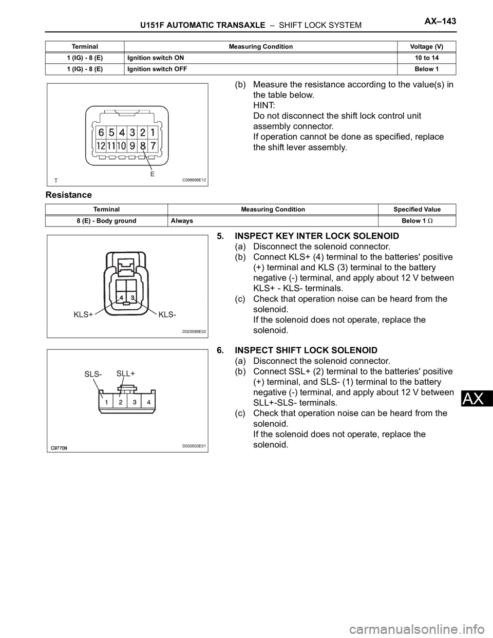
(b) Measure the resistance according to the value(s) in
the table below.
HINT:
Do not disconnect the shift lock control unit
assembly connector.
If operation cannot be done as specified, replace
the shift lever assembly.
Resistance
5. INSPECT KEY INTER LOCK SOLENOID
(a) Disconnect the solenoid connector.
(b) Connect KLS+ (4) terminal to the batteries' positive
(+) terminal and KLS (3) terminal to the battery
negative (-) terminal, and apply about 12 V between
KLS+ - KLS- terminals.
(c) Check that operation noise can be heard from the
solenoid.
If the solenoid does not operate, replace the
solenoid.
6. INSPECT SHIFT LOCK SOLENOID
(a) Disconnect the solenoid connector.
(b) Connect SSL+ (2) terminal to the batteries' positive
(+) terminal, and SLS- (1) terminal to the battery
negative (-) terminal, and apply about 12 V between
SLL+-SLS- terminals.
(c) Check that operation noise can be heard from the
solenoid.
If the solenoid does not operate, replace the
solenoid.
1 (IG) - 8 (E) Ignition switch ON10 to 14
1 (IG) - 8 (E) Ignition switch OFFBelow 1 Terminal Measuring Condition Voltage (V)
C098999E12
Terminal Measuring Condition Specified Value
8 (E) - Body ground AlwaysBelow 1
D025589E02
D030503E01
Page 1834 of 3000

AX–26U151F AUTOMATIC TRANSAXLE – AUTOMATIC TRANSAXLE SYSTEM
AX
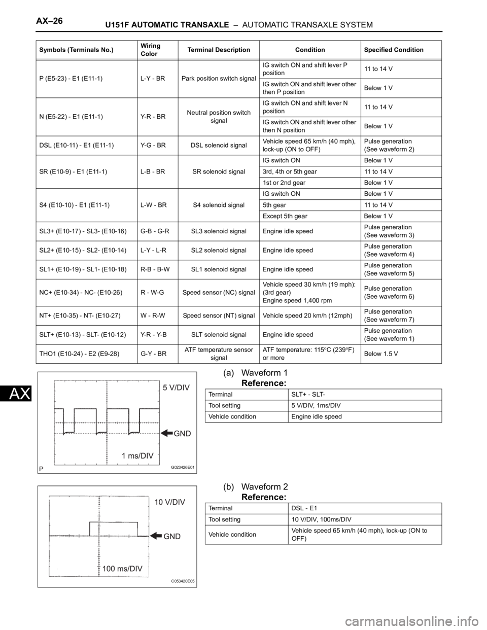
(a) Waveform 1
Reference:
(b) Waveform 2
Reference:
P (E5-23) - E1 (E11-1) L-Y - BR Park position switch signalIG switch ON and shift lever P
position11 to 14 V
IG switch ON and shift lever other
then P positionBelow 1 V
N (E5-22) - E1 (E11-1) Y-R - BRNeutral position switch
signalIG switch ON and shift lever N
position11 to 14 V
IG switch ON and shift lever other
then N positionBelow 1 V
DSL (E10-11) - E1 (E11-1) Y-G - BR DSL solenoid signalVehicle speed 65 km/h (40 mph),
lock-up (ON to OFF)Pulse generation
(See waveform 2)
SR (E10-9) - E1 (E11-1) L-B - BR SR solenoid signalIG switch ON Below 1 V
3rd, 4th or 5th gear 11 to 14 V
1st or 2nd gear Below 1 V
S4 (E10-10) - E1 (E11-1) L-W - BR S4 solenoid signalIG switch ON Below 1 V
5th gear 11 to 14 V
Except 5th gear Below 1 V
SL3+ (E10-17) - SL3- (E10-16) G-B - G-R SL3 solenoid signal Engine idle speedPulse generation
(See waveform 3)
SL2+ (E10-15) - SL2- (E10-14) L-Y - L-R SL2 solenoid signal Engine idle speedPulse generation
(See waveform 4)
SL1+ (E10-19) - SL1- (E10-18) R-B - B-W SL1 solenoid signal Engine idle speedPulse generation
(See waveform 5)
NC+ (E10-34) - NC- (E10-26) R - W-G Speed sensor (NC) signalVehicle speed 30 km/h (19 mph):
(3rd gear)
Engine speed 1,400 rpmPulse generation
(See waveform 6)
NT+ (E10-35) - NT- (E10-27) W - R-W Speed sensor (NT) signal Vehicle speed 20 km/h (12mph)Pulse generation
(See waveform 7)
SLT+ (E10-13) - SLT- (E10-12) Y-R - Y-B SLT solenoid signal Engine idle speedPulse generation
(See waveform 1)
THO1 (E10-24) - E2 (E9-28) G-Y - BRATF temperature sensor
signalATF temperature: 115
C (239F)
or moreBelow 1.5 V Symbols (Terminals No.)Wiring
ColorTerminal Description Condition Specified Condition
G023426E01
Terminal SLT+ - SLT-
Tool setting 5 V/DIV, 1ms/DIV
Vehicle condition Engine idle speed
C053420E05
Terminal DSL - E1
Tool setting 10 V/DIV, 100ms/DIV
Vehicle conditionVehicle speed 65 km/h (40 mph), lock-up (ON to
OFF)
Page 1858 of 3000
U151F AUTOMATIC TRANSAXLE – AUTOMATIC TRANSAXLE UNITAX–183
AX
9. INSPECT TRANSMISSION OIL CLEANER MAGNET
(a) Remove the magnets and use them to collect any
steel chips. Examine the chips and particles in the
pan and on the magnet to determine what type of
wear has occurred in the transaxle:
Result:
Steel (magnetic):
Wear of the bearing, gear and plate
Brass (non-magnetic):
Wear of the bushing
10. DISCONNECT TRANSMISSION WIRE
(a) Remove the 7 connectors from the shift solenoid
valves.
(b) Remove the bolt, lock plate and temperature
sensor.
11. REMOVE TRANSMISSION WIRE
(a) Remove the bolt and transmission wire from the
transaxle case.
12. REMOVE VALVE BODY OIL STRAINER ASSEMBLY
(a) Remove the 3 bolts and oil strainer.
(b) Remove the O-ring from the oil strainer.
AT00103E03
C091927E02
D003547E05
C091931
C091932E01
Page 1924 of 3000
U151F AUTOMATIC TRANSAXLE – AUTOMATIC TRANSAXLE UNITAX–183
AX
9. INSPECT TRANSMISSION OIL CLEANER MAGNET
(a) Remove the magnets and use them to collect any
steel chips. Examine the chips and particles in the
pan and on the magnet to determine what type of
wear has occurred in the transaxle:
Result:
Steel (magnetic):
Wear of the bearing, gear and plate
Brass (non-magnetic):
Wear of the bushing
10. DISCONNECT TRANSMISSION WIRE
(a) Remove the 7 connectors from the shift solenoid
valves.
(b) Remove the bolt, lock plate and temperature
sensor.
11. REMOVE TRANSMISSION WIRE
(a) Remove the bolt and transmission wire from the
transaxle case.
12. REMOVE VALVE BODY OIL STRAINER ASSEMBLY
(a) Remove the 3 bolts and oil strainer.
(b) Remove the O-ring from the oil strainer.
AT00103E03
C091927E02
D003547E05
C091931
C091932E01