Page 6 of 3000
PREPARATION – 2GR-FE ENGINE MECHANICALPP–5
PP
RECOMMENDED TOOLS
09011-12301 Socket Wrench 30 mm
09031-00040 Pin Punch
09040-00011 Hexagon Wrench Set
(09043-20050) Socket Hexagon Wrench 5
(09043-20060) Socket Hexagon Wrench 6
(09043-20100) Socket Hexagon Wrench 10
(09043-30140) Straight Hexagon Wrench 14
09043-50100 Bi-hexagon Wrench 10 mm
09090-04020 Engine Sling Device
09200-00010 Engine Adjust Kit
Page 7 of 3000
PP–6PREPARATION – 2GR-FE ENGINE MECHANICAL
PP
EQUIPMENT
Abrasive compound
Brush
Caliper gauge
Carbide cutter (30
)
Carbide cutter (45
)
Carbide cutter (60
)
Carbide cutter (75
)
Connecting rod aligner
Cylinder gauge
Dial indicator
Dye penetrant
Engine tune-up tester
Groove cleaning tool
Heater
Micrometer
Piston ring compressor
Piston ring expander
Plastigage
Precision straight edge
Press
Reamer (5.5 mm)
Ridge reamer
Soft brush
Solvent
Spring tester
Steel square
Thermometer
To r q u e w r e n c h
Torx socket wrench
Valve seat cutter
Valve guide bushing brush
V-block
Vernier calipers
Wire brush
Bar
Chain Block
CO/HC meter
Compression gauge
Dial indicator with magnetic base
Engine Sling Device
Feeler gauge
Radiator cap tester
Slide calipers
Tachometer
Timing light
Wooden block
Deep socket wrench
Screwdriver
Hammer
Page 8 of 3000
PREPARATION – 2GR-FE ENGINE MECHANICALPP–7
PPHINT:
Torx is registered trademark of Textron Inc.
Needle-noise plier
Compressed air
Magnetic finger
Plastic hammer
Gasket scraper
Piston
Nipper
Page 25 of 3000

EM–262GR-FE ENGINE MECHANICAL – ENGINE ASSEMBLY
EM
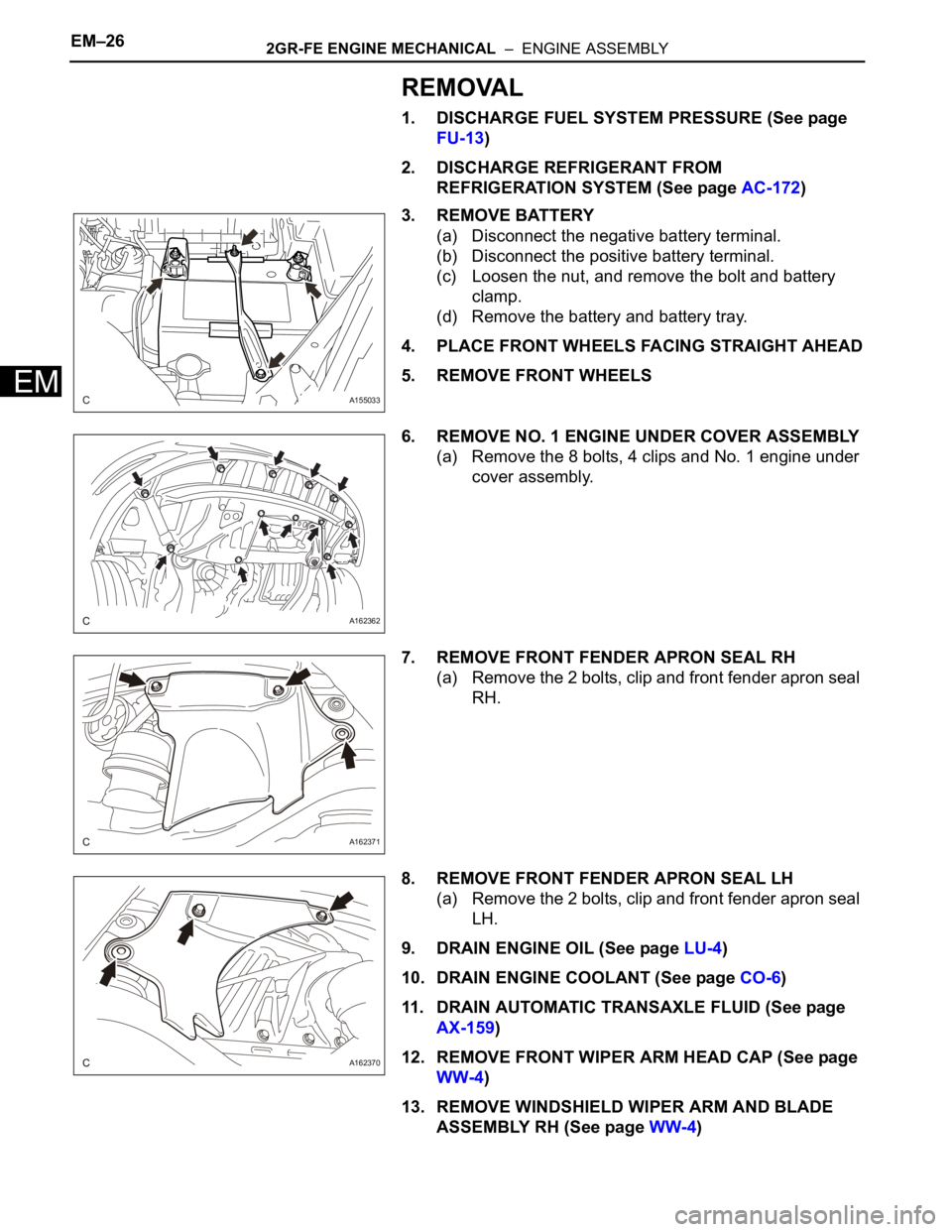
REMOVAL
1. DISCHARGE FUEL SYSTEM PRESSURE (See page
FU-13)
2. DISCHARGE REFRIGERANT FROM
REFRIGERATION SYSTEM (See page AC-172)
3. REMOVE BATTERY
(a) Disconnect the negative battery terminal.
(b) Disconnect the positive battery terminal.
(c) Loosen the nut, and remove the bolt and battery
clamp.
(d) Remove the battery and battery tray.
4. PLACE FRONT WHEELS FACING STRAIGHT AHEAD
5. REMOVE FRONT WHEELS
6. REMOVE NO. 1 ENGINE UNDER COVER ASSEMBLY
(a) Remove the 8 bolts, 4 clips and No. 1 engine under
cover assembly.
7. REMOVE FRONT FENDER APRON SEAL RH
(a) Remove the 2 bolts, clip and front fender apron seal
RH.
8. REMOVE FRONT FENDER APRON SEAL LH
(a) Remove the 2 bolts, clip and front fender apron seal
LH.
9. DRAIN ENGINE OIL (See page LU-4)
10. DRAIN ENGINE COOLANT (See page CO-6)
11. DRAIN AUTOMATIC TRANSAXLE FLUID (See page
AX-159)
12. REMOVE FRONT WIPER ARM HEAD CAP (See page
WW-4)
13. REMOVE WINDSHIELD WIPER ARM AND BLADE
ASSEMBLY RH (See page WW-4)
A155033
A162362
A162371
A162370
Page 26 of 3000
2GR-FE ENGINE MECHANICAL – ENGINE ASSEMBLYEM–27
EM
14. REMOVE WINDSHIELD WIPER ARM AND BLADE
ASSEMBLY LH (See page WW-4)
15. REMOVE COWL TOP VENTILATOR LOUVER SUB-
ASSEMBLY (See page WW-4)
16. REMOVE FRONT WIPER MOTOR AND LINK
ASSEMBLY (See page WW-4)
17. REMOVE NO. 1 COWL TOP TO COWL BRACE INNER
(a) Remove the 2 bolts, 2 clips and No. 1 cowl top to
cowl brace inner.
18. REMOVE FRONT OUTER COWL TOP PANEL SUB-
ASSEMBLY
(a) Remove the nut, and separate the fuel pump
resistor.
(b) Remove the 2 clips, and separate the engine wire.
(c) Remove the 7 bolts and front outer cowl top panel
sub-assembly.
A162366
A162375
A162368
A162367
Page 27 of 3000

EM–282GR-FE ENGINE MECHANICAL – ENGINE ASSEMBLY
EM
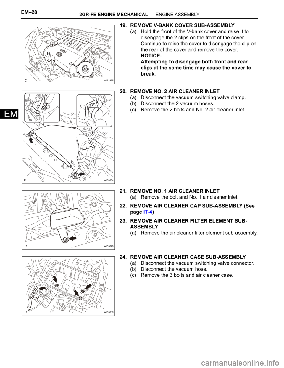
19. REMOVE V-BANK COVER SUB-ASSEMBLY
(a) Hold the front of the V-bank cover and raise it to
disengage the 2 clips on the front of the cover.
Continue to raise the cover to disengage the clip on
the rear of the cover and remove the cover.
NOTICE:
Attempting to disengage both front and rear
clips at the same time may cause the cover to
break.
20. REMOVE NO. 2 AIR CLEANER INLET
(a) Disconnect the vacuum switching valve clamp.
(b) Disconnect the 2 vacuum hoses.
(c) Remove the 2 bolts and No. 2 air cleaner inlet.
21. REMOVE NO. 1 AIR CLEANER INLET
(a) Remove the bolt and No. 1 air cleaner inlet.
22. REMOVE AIR CLEANER CAP SUB-ASSEMBLY (See
page IT-4)
23. REMOVE AIR CLEANER FILTER ELEMENT SUB-
ASSEMBLY
(a) Remove the air cleaner filter element sub-assembly.
24. REMOVE AIR CLEANER CASE SUB-ASSEMBLY
(a) Disconnect the vacuum switching valve connector.
(b) Disconnect the vacuum hose.
(c) Remove the 3 bolts and air cleaner case.
A162365
A133004
A155040
A155039
Page 28 of 3000
2GR-FE ENGINE MECHANICAL – ENGINE ASSEMBLYEM–29
EM
25. REMOVE AIR CLEANER BRACKET
(a) Remove the 2 bolts and air cleaner bracket.
26. REMOVE INTAKE AIR RESONATOR SUB-ASSEMBLY
(a) Remove the clip, bolt and intake air resonator.
27. REMOVE NO. 2 ENGINE MOUNTING STAY RH
(a) Remove bolt, 2 nuts and No. 2 engine mounting
stay RH.
28. REMOVE ENGINE MOVING CONTROL ROD
(a) Remove the 3 bolts and engine moving control rod.
29. DISCONNECT NO. 1 FUEL VAPOR FEED HOSE
(a) Remove the clamp and disconnect the No. 1 fuel
vapor feed hose.
A155041
A155042
A139217
A162369
A155036
Page 29 of 3000
EM–302GR-FE ENGINE MECHANICAL – ENGINE ASSEMBLY
EM
30. DISCONNECT RADIATOR INLET HOSE
(a) Using pliers, grip the claws of the clip and slide the
clip to disconnect radiator inlet hose from the water
outlet.
31. DISCONNECT RADIATOR OUTLET HOSE
(a) Using pliers, grip the claws of the clip and slide the
clip to disconnect the radiator outlet hose from the
water inlet.
32. DISCONNECT HEATER WATER OUTLET HOSE B
(a) Using pliers, grip the claws of the clip and slide the
clip to disconnect heater water inlet hose B from the
water inlet.
33. DISCONNECT HEATER WATER INLET HOSE B
(a) Using pliers, grip the claws of the clip and slide the
clip to disconnect heater water outlet hose B from
the water outlet.
34. DISCONNECT FUEL TUBE SUB-ASSEMBLY
(a) Remove the No. 1 fuel pipe clamp.
A155046
A155038
A155044
A155043
A155045