2007 TOYOTA SIENNA fuel cap
[x] Cancel search: fuel capPage 21 of 3000
2GR-FE ENGINE CONTROL SYSTEM – KNOCK SENSORES–521
ES
REMOVAL
1. DISCHARGE FUEL SYSTEM PRESSURE
(See page FU-13)
2. REMOVE V-BANK COVER SUB-ASSEMBLY (See
page EM-28)
3. DRAIN ENGINE COOLANT (See page CO-6)
4. REMOVE WINDSHIELD WIPER MOTOR ASSEMBLY
HINT:
(See page WW-4)
5. REMOVE FRONT OUTER COWL TOP PANEL SUB-
ASSEMBLY (See page EM-27)
6. REMOVE AIR CLEANER CAP SUB-ASSEMBLY (See
page ES-493)
7. REMOVE AIR CLEANER CASE SUB-ASSEMBLY (See
page EM-28)
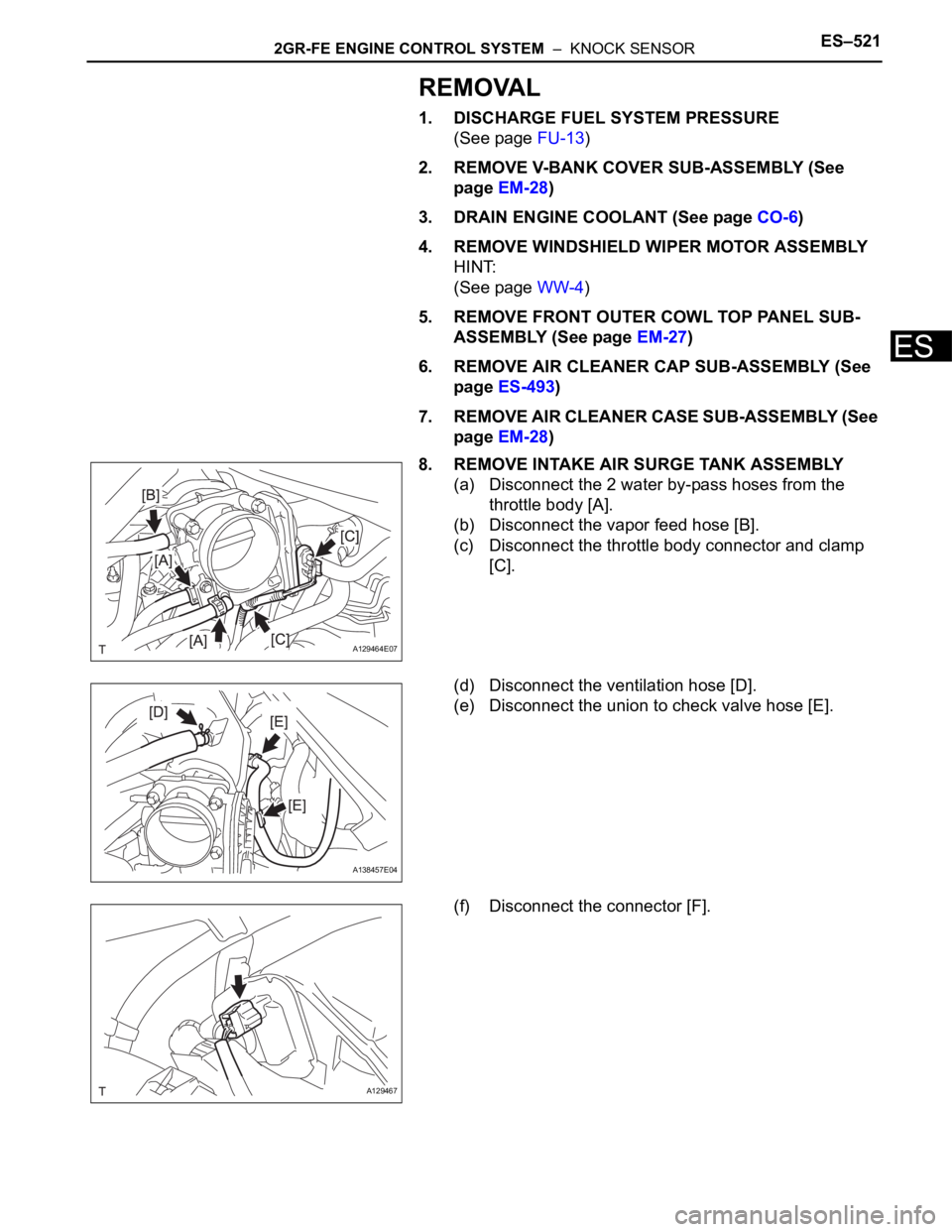
8. REMOVE INTAKE AIR SURGE TANK ASSEMBLY
(a) Disconnect the 2 water by-pass hoses from the
throttle body [A].
(b) Disconnect the vapor feed hose [B].
(c) Disconnect the throttle body connector and clamp
[C].
(d) Disconnect the ventilation hose [D].
(e) Disconnect the union to check valve hose [E].
(f) Disconnect the connector [F].
A129464E07
A138457E04
A129467
Page 23 of 3000
![TOYOTA SIENNA 2007 Service Repair Manual 2GR-FE ENGINE CONTROL SYSTEM – KNOCK SENSORES–523
ES
(a) Install a new gasket to the intake air surge tank [A].
(b) Using a 5 mm hexagon socket wrench, install the 4
bolts [B].
Torque: 18 N*m ( TOYOTA SIENNA 2007 Service Repair Manual 2GR-FE ENGINE CONTROL SYSTEM – KNOCK SENSORES–523
ES
(a) Install a new gasket to the intake air surge tank [A].
(b) Using a 5 mm hexagon socket wrench, install the 4
bolts [B].
Torque: 18 N*m (](/manual-img/14/57466/w960_57466-22.png)
2GR-FE ENGINE CONTROL SYSTEM – KNOCK SENSORES–523
ES
(a) Install a new gasket to the intake air surge tank [A].
(b) Using a 5 mm hexagon socket wrench, install the 4
bolts [B].
Torque: 18 N*m (184 kgf*cm, 13 ft.*lbf)
(c) Install the intake air surge tank with the 2 nuts and 2
bolts [C].
Torque: Nut
16 N*m (163 kgf*cm, 12 ft.*lbf)
Bolt
21 N*m (214 kgf*cm, 15 ft.*lbf)
(d) Connect the connector [D].
(e) Connect the union to check valve hose [E].
(f) Connect the ventilation hose No. 2 [F].
(g) Install the clamp and connect the throttle with motor
body assembly connector [G].
(h) Connect the vapor feed hose [H].
(i) Connect the 2 water by-pass hoses to the throttle
with motor body assembly [I].
5. INSTALL AIR CLEANER CASE SUB-ASSEMBLY (See
page EM-59)
6. INSTALL AIR CLEANER CAP SUB-ASSEMBLY (See
page ES-496)
7. ADD ENGINE COOLANT (See page CO-7)
8. INSPECT FOR ENGINE COOLANT LEAK (See page
CO-1)
9. INSPECT FOR FUEL LEAK (See page FU-7)
10. INSTALL FRONT OUTER COWL TOP PANEL SUB-
ASSEMBLY (See page EM-61)
11. INSTALL WINDSHIELD WIPER MOTOR ASSEMBLY
HINT:
(See page WW-5)
A129468E09
A129467
A138457E05
A129464E08
Page 25 of 3000
EM–262GR-FE ENGINE MECHANICAL – ENGINE ASSEMBLY
EM
REMOVAL
1. DISCHARGE FUEL SYSTEM PRESSURE (See page
FU-13)
2. DISCHARGE REFRIGERANT FROM
REFRIGERATION SYSTEM (See page AC-172)
3. REMOVE BATTERY
(a) Disconnect the negative battery terminal.
(b) Disconnect the positive battery terminal.
(c) Loosen the nut, and remove the bolt and battery
clamp.
(d) Remove the battery and battery tray.
4. PLACE FRONT WHEELS FACING STRAIGHT AHEAD
5. REMOVE FRONT WHEELS
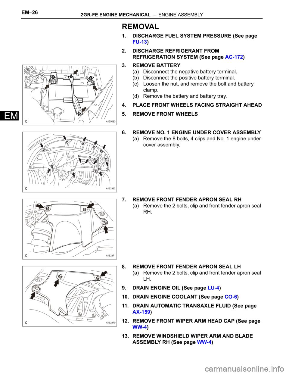
6. REMOVE NO. 1 ENGINE UNDER COVER ASSEMBLY
(a) Remove the 8 bolts, 4 clips and No. 1 engine under
cover assembly.
7. REMOVE FRONT FENDER APRON SEAL RH
(a) Remove the 2 bolts, clip and front fender apron seal
RH.
8. REMOVE FRONT FENDER APRON SEAL LH
(a) Remove the 2 bolts, clip and front fender apron seal
LH.
9. DRAIN ENGINE OIL (See page LU-4)
10. DRAIN ENGINE COOLANT (See page CO-6)
11. DRAIN AUTOMATIC TRANSAXLE FLUID (See page
AX-159)
12. REMOVE FRONT WIPER ARM HEAD CAP (See page
WW-4)
13. REMOVE WINDSHIELD WIPER ARM AND BLADE
ASSEMBLY RH (See page WW-4)
A155033
A162362
A162371
A162370
Page 44 of 3000
2GR-FE EMISSION CONTROL – EMISSION CONTROL SYSTEMEC–5
EC
ON-VEHICLE INSPECTION
1. INSPECT FUEL CUT RPM
(a) Increase the engine speed to at least 3500 rpm.
(b) Use a sound scope to check for injector operating
sounds.
(c) Check that when the throttle lever is released,
injector operating sounds stop momentarily (at 2500
rpm) and then resume (at 1400 rpm).
Standard
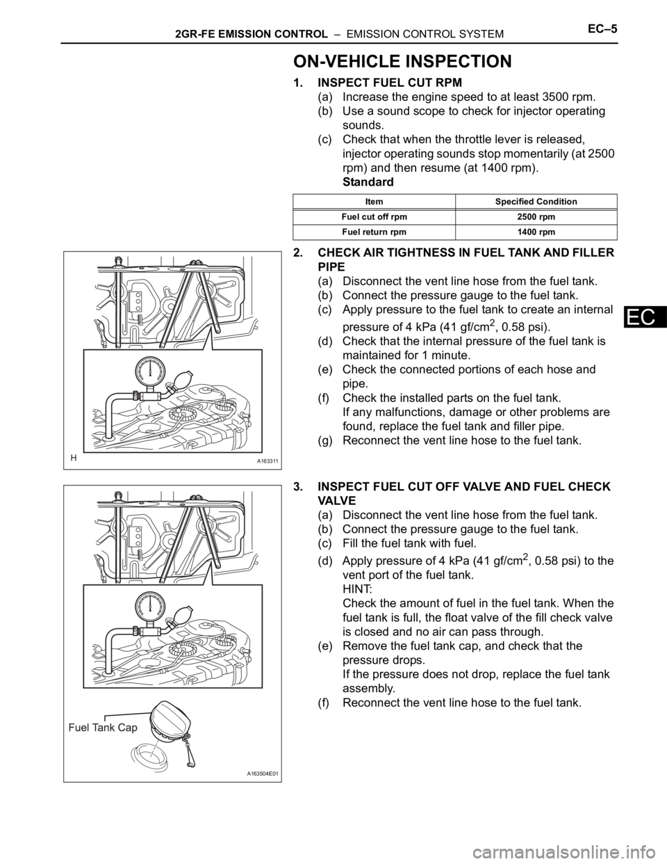
2. CHECK AIR TIGHTNESS IN FUEL TANK AND FILLER
PIPE
(a) Disconnect the vent line hose from the fuel tank.
(b) Connect the pressure gauge to the fuel tank.
(c) Apply pressure to the fuel tank to create an internal
pressure of 4 kPa (41 gf/cm
2, 0.58 psi).
(d) Check that the internal pressure of the fuel tank is
maintained for 1 minute.
(e) Check the connected portions of each hose and
pipe.
(f) Check the installed parts on the fuel tank.
If any malfunctions, damage or other problems are
found, replace the fuel tank and filler pipe.
(g) Reconnect the vent line hose to the fuel tank.
3. INSPECT FUEL CUT OFF VALVE AND FUEL CHECK
VA LV E
(a) Disconnect the vent line hose from the fuel tank.
(b) Connect the pressure gauge to the fuel tank.
(c) Fill the fuel tank with fuel.
(d) Apply pressure of 4 kPa (41 gf/cm
2, 0.58 psi) to the
vent port of the fuel tank.
HINT:
Check the amount of fuel in the fuel tank. When the
fuel tank is full, the float valve of the fill check valve
is closed and no air can pass through.
(e) Remove the fuel tank cap, and check that the
pressure drops.
If the pressure does not drop, replace the fuel tank
assembly.
(f) Reconnect the vent line hose to the fuel tank.
Item Specified Condition
Fuel cut off rpm 2500 rpm
Fuel return rpm 1400 rpm
A163311
A163504E01
Page 326 of 3000

ES–2582GR-FE ENGINE CONTROL SYSTEM – SFI SYSTEM
ES
MONITOR DESCRIPTION
The ECM uses the sensors mounted in front of and behind the three-way catalyst (TWC) to monitor its
efficiency. The first sensor, an Air Fuel ratio (A/F) sensor, sends pre-catalyst A/F ratio information to the
ECM. The second sensor, a heated oxygen sensor (O2S), sends post-catalyst information to the ECM.
The ECM compares these 2 signals to judge the efficiency of the catalyst and the catalyst's ability to store
oxygen. During normal operation, the TWC stores and releases oxygen as needed. The capacity to store
oxygen results in a low variation in the post-TWC exhaust stream.
If the catalyst is functioning normally, the waveform of the heated oxygen sensor slowly switches between
RICH and LEAN. If the catalyst is deteriorated, the waveform will alternate frequently between RICH and
LEAN. As the catalyst efficiency degrades, its ability to store oxygen is reduced and the catalyst output
becomes more variable. When running the monitor, the ECM compares sensor 1 signals (A/F sensor)
over a specific amount of time to determine catalyst efficiency. The ECM begins by calculating the signal
length for both sensors (for the rear oxygen sensor, the ECM uses the output voltage signal length). If the
oxygen sensor output voltage signal length is greater than the threshold (threshold is calculated based on
the A/F sensor signal length), the ECM concludes that the catalyst is malfunctioning. The ECM will turn on
the MIL and a DTC will be set.
HINT:
• Bank 1 refers to the bank that includes cylinder No. 1.
• Bank 2 refers to the bank that does not include cylinder No. 1.
• Sensor 1 refers to the sensor closest to the engine assembly.
• Sensor 2 refers to the sensor farthest away from the engine assembly.
MONITOR STRATEGY
DTC P0420Catalyst System Efficiency Below Threshold
(Bank 1)
DTC P0430Catalyst System Efficiency Below Threshold
(Bank 2)
DTC No. DTC Detection Condition Trouble Area
P0420Oxygen Storage Capacity (OSC) value is smaller than
standard value under active air-fuel ratio control (2 trip
detection logic)• Gas leakage from exhaust system
• A/F sensor (bank 1 sensor 1)
• HO2 sensor (bank 1 sensor 2)
• Exhaust manifold (TWC)
P0430OSC value is smaller than standard value under active
air-fuel ratio control (2 trip detection logic)• Gas leakage from exhaust system
• A/F sensor (bank 2 sensor 1)
• HO2 sensor (bank 2 sensor 2)
• Exhaust manifold (TWC)
Related DTCsP0420: Catalyst Deterioration
P0430: Catalyst Deterioration
Required Sensors / Components (Main) TWC
Required Sensors / Components (Related)A/F sensor, heated oxygen sensor, intake air temperature sensor, mass air flow
meter, crankshaft position sensor and engine coolant temperature sensor
Frequency of Operation Once per driving cycle
Duration Approximately 30 seconds
MIL Operation 2 driving cycles
Sequence of Operation None
Page 327 of 3000
2GR-FE ENGINE CONTROL SYSTEM – SFI SYSTEMES–259
ES
TYPICAL ENABLING CONDITIONS
TYPICAL MALFUNCTION THRESHOLDS
MONITOR RESULT
Refer to CHECKING MONITOR STATUS (See page ES-19).
CONDITIONING FOR SENSOR TESTING
HINT:
Perform the operation with the engine speeds and durations described below prior to checking the
waveforms of the A/F and HO2 sensors. This is in order to activate the sensors sufficiently to obtain the
appropriate inspection results.
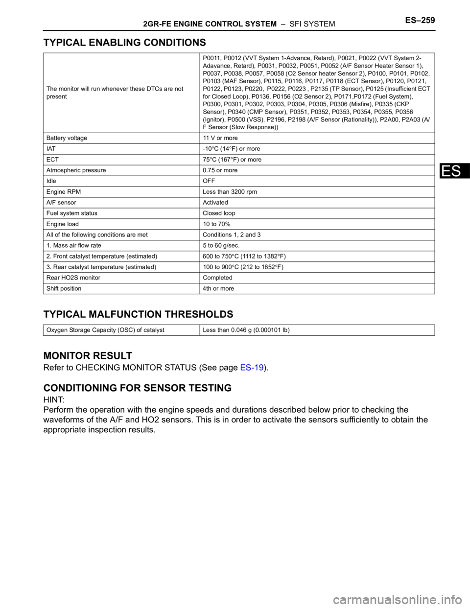
The monitor will run whenever these DTCs are not
presentP0011, P0012 (VVT System 1-Advance, Retard), P0021, P0022 (VVT System 2-
Adavance, Retard), P0031, P0032, P0051, P0052 (A/F Sensor Heater Sensor 1),
P0037, P0038, P0057, P0058 (O2 Sensor heater Sensor 2), P0100, P0101, P0102,
P0103 (MAF Sensor), P0115, P0116, P0117, P0118 (ECT Sensor), P0120, P0121,
P0122, P0123, P0220, P0222, P0223 , P2135 (TP Sensor), P0125 (Insufficient ECT
for Closed Loop), P0136, P0156 (O2 Sensor 2), P0171,P0172 (Fuel System),
P0300, P0301, P0302, P0303, P0304, P0305, P0306 (Misfire), P0335 (CKP
Sensor), P0340 (CMP Sensor), P0351, P0352, P0353, P0354, P0355, P0356
(Ignitor), P0500 (VSS), P2196, P2198 (A/F Sensor (Rationality)), P2A00, P2A03 (A/
F Sensor (Slow Response))
Battery voltage 11 V or more
IAT -10
C (14F) or more
ECT 75
C (167F) or more
Atmospheric pressure 0.75 or more
Idle OFF
Engine RPM Less than 3200 rpm
A/F sensor Activated
Fuel system status Closed loop
Engine load 10 to 70%
All of the following conditions are met Conditions 1, 2 and 3
1. Mass air flow rate 5 to 60 g/sec.
2. Front catalyst temperature (estimated) 600 to 750
C (1112 to 1382F)
3. Rear catalyst temperature (estimated) 100 to 900
C (212 to 1652F)
Rear HO2S monitor Completed
Shift position 4th or more
Oxygen Storage Capacity (OSC) of catalyst Less than 0.046 g (0.000101 lb)
Page 382 of 3000
ES–762GR-FE ENGINE CONTROL SYSTEM – SFI SYSTEM
ES
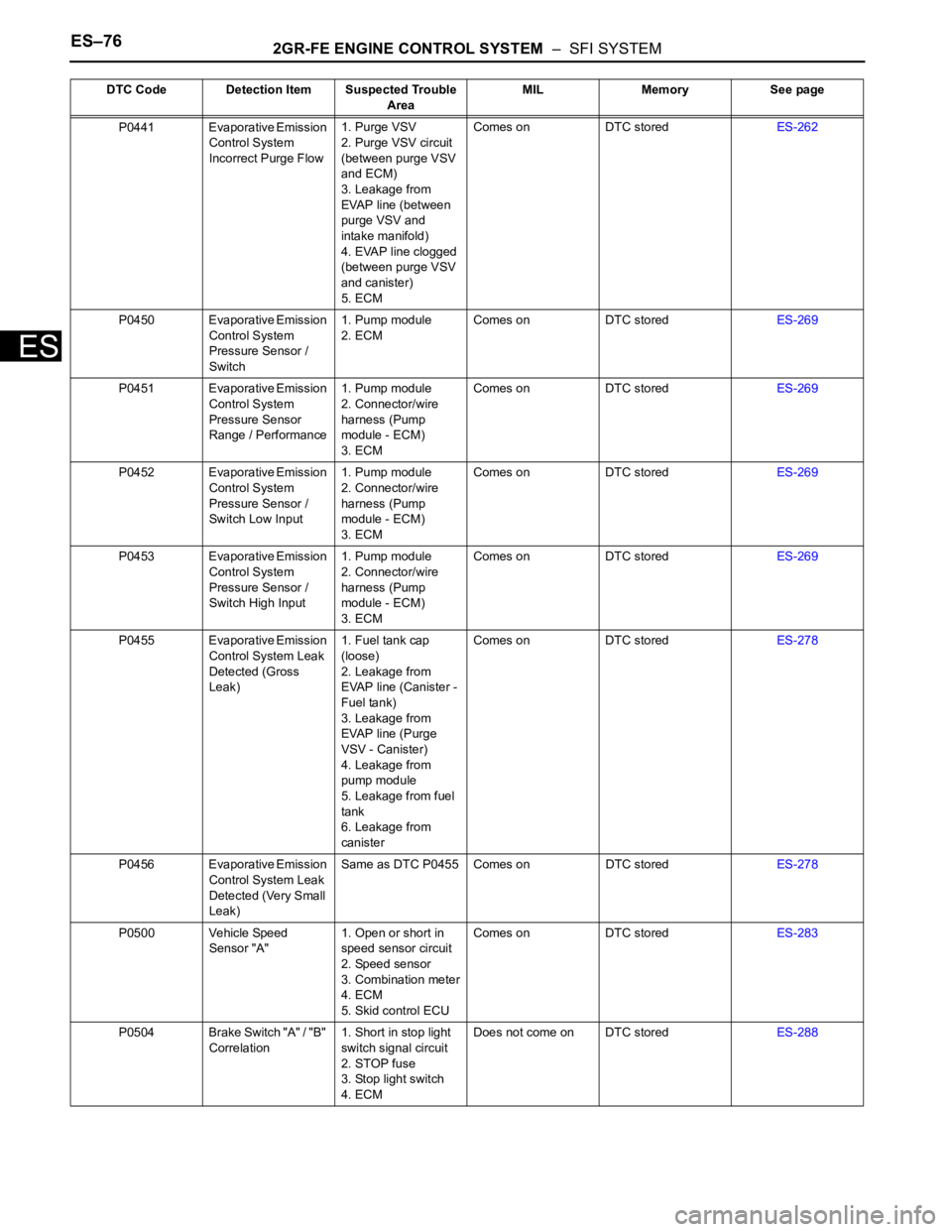
P0441 Evaporative Emission
Control System
Incorrect Purge Flow1. Purge VSV
2. Purge VSV circuit
(between purge VSV
and ECM)
3. Leakage from
EVAP line (between
purge VSV and
intake manifold)
4. EVAP line clogged
(between purge VSV
and canister)
5. ECMComes on DTC storedES-262
P0450 Evaporative Emission
Control System
Pressure Sensor /
Switch1. Pump module
2. ECMComes on DTC storedES-269
P0451 Evaporative Emission
Control System
Pressure Sensor
Range / Performance1. Pump module
2. Connector/wire
harness (Pump
module - ECM)
3. ECMComes on DTC storedES-269
P0452 Evaporative Emission
Control System
Pressure Sensor /
Switch Low Input1. Pump module
2. Connector/wire
harness (Pump
module - ECM)
3. ECMComes on DTC storedES-269
P0453 Evaporative Emission
Control System
Pressure Sensor /
Switch High Input1. Pump module
2. Connector/wire
harness (Pump
module - ECM)
3. ECMComes on DTC storedES-269
P0455 Evaporative Emission
Control System Leak
Detected (Gross
Leak)1. Fuel tank cap
(loose)
2. Leakage from
EVAP line (Canister -
Fuel tank)
3. Leakage from
EVAP line (Purge
VSV - Canister)
4. Leakage from
pump module
5. Leakage from fuel
tank
6. Leakage from
canisterComes on DTC storedES-278
P0456 Evaporative Emission
Control System Leak
Detected (Very Small
Leak)Same as DTC P0455 Comes on DTC storedES-278
P0500 Vehicle Speed
Sensor "A"1. Open or short in
speed sensor circuit
2. Speed sensor
3. Combination meter
4. ECM
5. Skid control ECUComes on DTC storedES-283
P0504 Brake Switch "A" / "B"
Correlation1. Short in stop light
switch signal circuit
2. STOP fuse
3. Stop light switch
4. ECMDoes not come on DTC storedES-288 DTC Code Detection Item Suspected Trouble
AreaMIL Memory See page
Page 476 of 3000
ES–1702GR-FE ENGINE CONTROL SYSTEM – SFI SYSTEM
ES
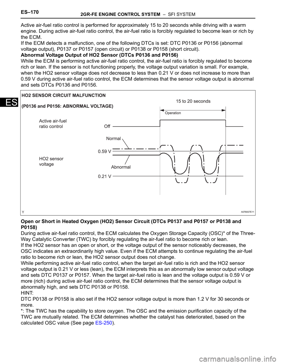
Active air-fuel ratio control is performed for approximately 15 to 20 seconds while driving with a warm
engine. During active air-fuel ratio control, the air-fuel ratio is forcibly regulated to become lean or rich by
the ECM.
If the ECM detects a malfunction, one of the following DTCs is set: DTC P0136 or P0156 (abnormal
voltage output), P0137 or P0157 (open circuit) or P0138 or P0158 (short circuit).
Abnormal Voltage Output of HO2 Sensor (DTCs P0136 and P0156)
While the ECM is performing active air-fuel ratio control, the air-fuel ratio is forcibly regulated to become
rich or lean. If the sensor is not functioning properly, the voltage output variation is small. For example,
when the HO2 sensor voltage does not decrease to less than 0.21 V or does not increase to more than
0.59 V during active air-fuel ratio control, the ECM determines that the sensor voltage output is abnormal
and sets DTCs P0136 and P0156.
Open or Short in Heated Oxygen (HO2) Sensor Circuit (DTCs P0137 and P0157 or P0138 and
P0158)
During active air-fuel ratio control, the ECM calculates the Oxygen Storage Capacity (OSC)* of the Three-
Way Catalytic Converter (TWC) by forcibly regulating the air-fuel ratio to become rich or lean.
If the HO2 sensor has an open or short, or the voltage output of the sensor noticeably decreases, the
OSC indicates an extraordinarily high value. Even if the ECM attempts to continue regulating the air-fuel
ratio to become rich or lean, the HO2 sensor output does not change.
While performing active air-fuel ratio control, when the target air-fuel ratio is rich and the HO2 sensor
voltage output is 0.21 V or less (lean), the ECM interprets this as an abnormally low sensor output voltage
and sets DTC P0137 or P0157. When the target air-fuel ratio is lean and the voltage output is 0.59 V or
more (rich) during active air-fuel ratio control, the ECM determines that the sensor voltage output is
abnormally high, and sets DTC P0138 or P0158.
HINT:
DTC P0138 or P0158 is also set if the HO2 sensor voltage output is more than 1.2 V for 30 seconds or
more.
*: The TWC has the capability to store oxygen. The OSC and the emission purification capacity of the
TWC are mutually related. The ECM determines whether the catalyst has deteriorated, based on the
calculated OSC value (See page ES-250).
A076837E11