Page 1122 of 3000

2GR-FE FUEL – FUEL SYSTEMFU–1
FU
FUEL SYSTEM
PRECAUTION
1. PRECAUTION
(a) Before inspecting and repairing the fuel system,
disconnect the cable from the negative (-) battery
terminal.
(b) Do not smoke or work near fire when handling the
fuel system.
(c) Keep gasoline away from rubber or leather parts.
2. DISCHARGE FUEL SYSTEM PRESSURE (*1)
CAUTION:
• Perform the following procedures to prevent fuel
from spilling out before removing any fuel system
parts.
• Pressure will still remain in the fuel line even after
performing the following procedures. When
disconnecting the fuel line, cover it with a shop
rag or a piece of cloth to prevent fuel from
spraying or coming out.
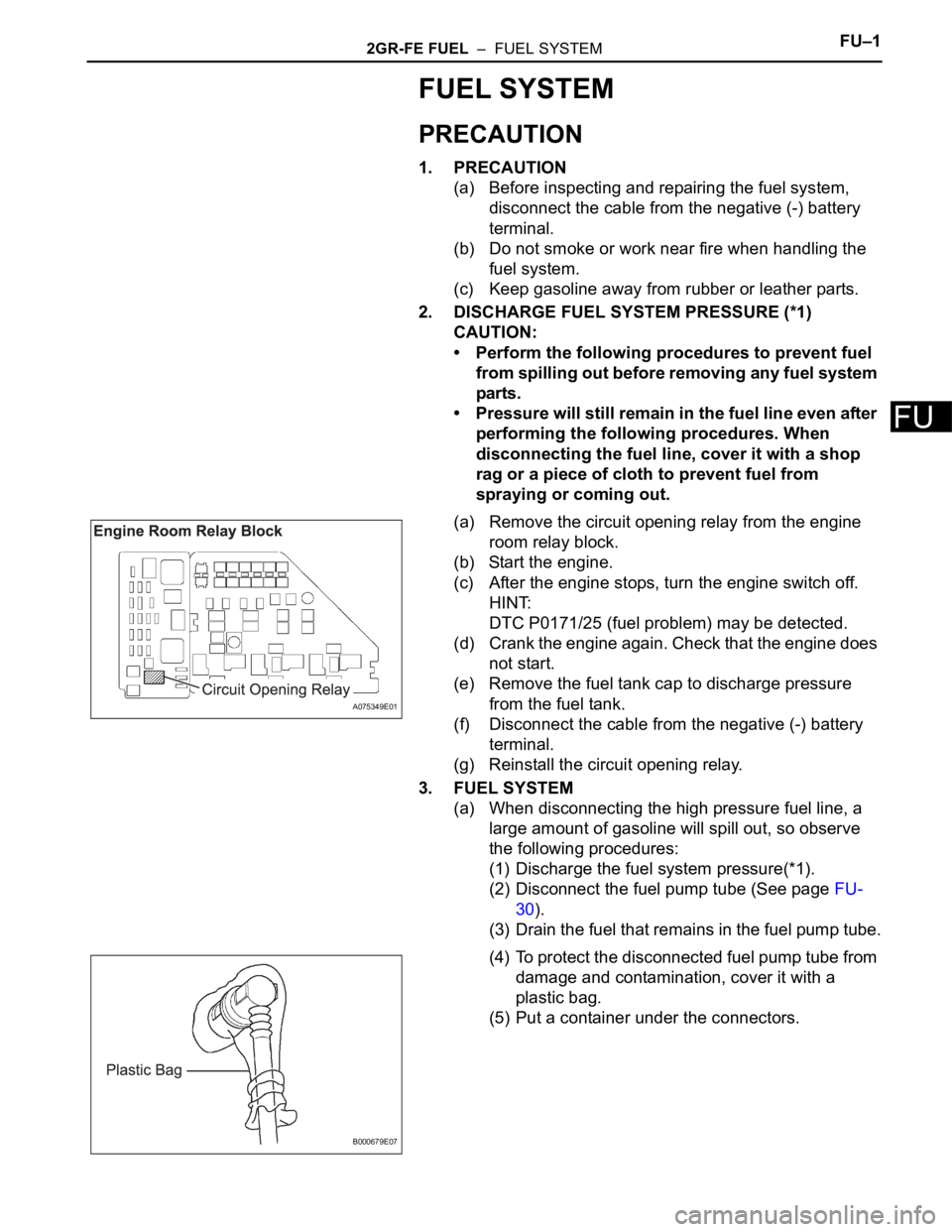
(a) Remove the circuit opening relay from the engine
room relay block.
(b) Start the engine.
(c) After the engine stops, turn the engine switch off.
HINT:
DTC P0171/25 (fuel problem) may be detected.
(d) Crank the engine again. Check that the engine does
not start.
(e) Remove the fuel tank cap to discharge pressure
from the fuel tank.
(f) Disconnect the cable from the negative (-) battery
terminal.
(g) Reinstall the circuit opening relay.
3. FUEL SYSTEM
(a) When disconnecting the high pressure fuel line, a
large amount of gasoline will spill out, so observe
the following procedures:
(1) Discharge the fuel system pressure(*1).
(2) Disconnect the fuel pump tube (See page FU-
30).
(3) Drain the fuel that remains in the fuel pump tube.
(4) To protect the disconnected fuel pump tube from
damage and contamination, cover it with a
plastic bag.
(5) Put a container under the connectors.
A075349E01
B000679E07
Page 1132 of 3000
FU–202GR-FE FUEL – FUEL INJECTOR
FU
(e) Connect the union to check valve hose. (*1)
(f) Connect the No. 1 ventilation hose. (*2)
(g) Install the clamp and connect the throttle with motor
body assembly connector. (*3)
(h) Connect the vapor feed hose assembly. (*4)
(i) Connect the 2 water by-pass hoses to the throttle
with motor body assembly. (*5)
4. INSTALL AIR CLEANER CAP SUB-ASSEMBLY
(a) Install the 2 bolts and air cleaner cap sub-assembly.
(b) Connect the No. 2 ventilation hose and air cleaner
hose band.
(c) Connect the vacuum hose (EVAP) to the air cleaner
hose.
(d) Connect the 3 vacuum hoses.
5. ADD ENGINE COOLANT (See page CO-7)
6. CONNECT CABLE TO NEGATIVE BATTERY
TERMINAL
7. INSPECT FOR ENGINE COOLANT LEAK (See page
CO-1)
8. INSTALL NO. 1 ENGINE UNDER COVER
9. INSPECT FOR FUEL LEAK (See page FU-7)
A162431E01
A129464E10
A163204
A135113E01
A135112E01
Page 1134 of 3000
2GR-FE FUEL – FUEL INJECTORFU–13
FU
REMOVAL
1. DISCHARGE FUEL SYSTEM PRESSURE
HINT:
See page FU-1.
2. DISCONNECT CABLE FROM NEGATIVE BATTERY
TERMINAL
3. REMOVE NO. 1 ENGINE UNDER COVER
4. DRAIN ENGINE COOLANT (See page CO-6)
5. REMOVE FRONT WIPER ARM HEAD CAP (See page
WW-4)
6. REMOVE FRONT WIPER ARM RH (See page WW-4)
7. REMOVE FRONT WIPER ARM LH (See page WW-4)
8. REMOVE COWL TOP VENTILATOR LOUVER SUB-
ASSEMBLY (See page WW-4)
9. REMOVE WINDSHIELD WIPER MOTOR AND LINK
ASSEMBLY (See page WW-4)
10. REMOVE NO. 1 COWL TOP TO COWL BRACE INNER
(a) Remove the 2 bolts and the No. 1 cowl top to cowl
brace inner.
11. REMOVE COWL TOP PANEL SUB-ASSEMBLY
OUTER FRONT
(a) Remove the wire harness clamp.
(b) Disconnect the fuel pump resistor connector.
(c) Remove the 7 bolts and the cowl top panel outer
front.
12. REMOVE V-BANK COVER SUB-ASSEMBLY (See
page EM-28)
13. REMOVE AIR CLEANER CAP SUB-ASSEMBLY
(a) Disconnect the 3 vacuum hoses.
A162429
A162430
A135112E01
Page 1135 of 3000
FU–142GR-FE FUEL – FUEL INJECTOR
FU
(b) Remove the No. 2 ventilation hose and air cleaner
hose band.
(c) Disconnect the vacuum hose (EVAP) from the air
cleaner hose.
(d) Remove the 2 bolts and air cleaner cap sub-
assembly.
14. REMOVE INTAKE AIR SURGE TANK ASSEMBLY
(a) Disconnect the 2 water by-pass hoses from the
throttle with motor body assembly. (*1)
(b) Disconnect the fuel vapor feed hose assembly.(*2)
(c) Disconnect the throttle with motor body assembly
connector and clamp. (*3)
(d) Disconnect the No. 1 ventilation hose. (*4)
(e) Disconnect the union to check valve hose. (*5)
(f) Disconnect the connector.
A135113E01
A163204
A129464E10
A162431E01
A129467
Page 1141 of 3000
FU–202GR-FE FUEL – FUEL INJECTOR
FU
(e) Connect the union to check valve hose. (*1)
(f) Connect the No. 1 ventilation hose. (*2)
(g) Install the clamp and connect the throttle with motor
body assembly connector. (*3)
(h) Connect the vapor feed hose assembly. (*4)
(i) Connect the 2 water by-pass hoses to the throttle
with motor body assembly. (*5)
4. INSTALL AIR CLEANER CAP SUB-ASSEMBLY
(a) Install the 2 bolts and air cleaner cap sub-assembly.
(b) Connect the No. 2 ventilation hose and air cleaner
hose band.
(c) Connect the vacuum hose (EVAP) to the air cleaner
hose.
(d) Connect the 3 vacuum hoses.
5. ADD ENGINE COOLANT (See page CO-7)
6. CONNECT CABLE TO NEGATIVE BATTERY
TERMINAL
7. INSPECT FOR ENGINE COOLANT LEAK (See page
CO-1)
8. INSTALL NO. 1 ENGINE UNDER COVER
9. INSPECT FOR FUEL LEAK (See page FU-7)
A162431E01
A129464E10
A163204
A135113E01
A135112E01
Page 1143 of 3000

2GR-FE FUEL – FUEL PRESSURE PULSATION DAMPERFU–25
FU
REMOVAL
1. DISCHARGE FUEL SYSTEM PRESSURE
HINT:
See page FU-1.
2. DISCONNECT CABLE FROM NEGATIVE BATTERY
TERMINAL
3. REMOVE NO. 1 ENGINE UNDER COVER
4. DRAIN ENGINE COOLANT (See page CO-6)
5. REMOVE FRONT WIPER ARM HEAD CAP (See page
WW-4)
6. REMOVE FRONT WIPER ARM RH (See page WW-4)
7. REMOVE FRONT WIPER ARM LH (See page WW-4)
8. REMOVE COWL TOP VENTILATOR LOUVER SUB-
ASSEMBLY (See page WW-4)
9. REMOVE WINDSHIELD WIPER MOTOR AND LINK
ASSEMBLY (See page WW-4)
10. REMOVE NO. 1 COWL TOP TO COWL BRACE INNER
(See page FU-13)
11. REMOVE COWL TOP PANEL SUB-ASSEMBLY
OUTER FRONT (See page FU-13)
12. REMOVE V-BANK COVER SUB-ASSEMBLY (See
page EM-28)
13. REMOVE AIR CLEANER CAP SUB-ASSEMBLY (See
page FU-13)
14. REMOVE INTAKE AIR SURGE TANK ASSEMBLY
(See page FU-14)
15. REMOVE FUEL PRESSURE PULSATION DAMPER
ASSEMBLY
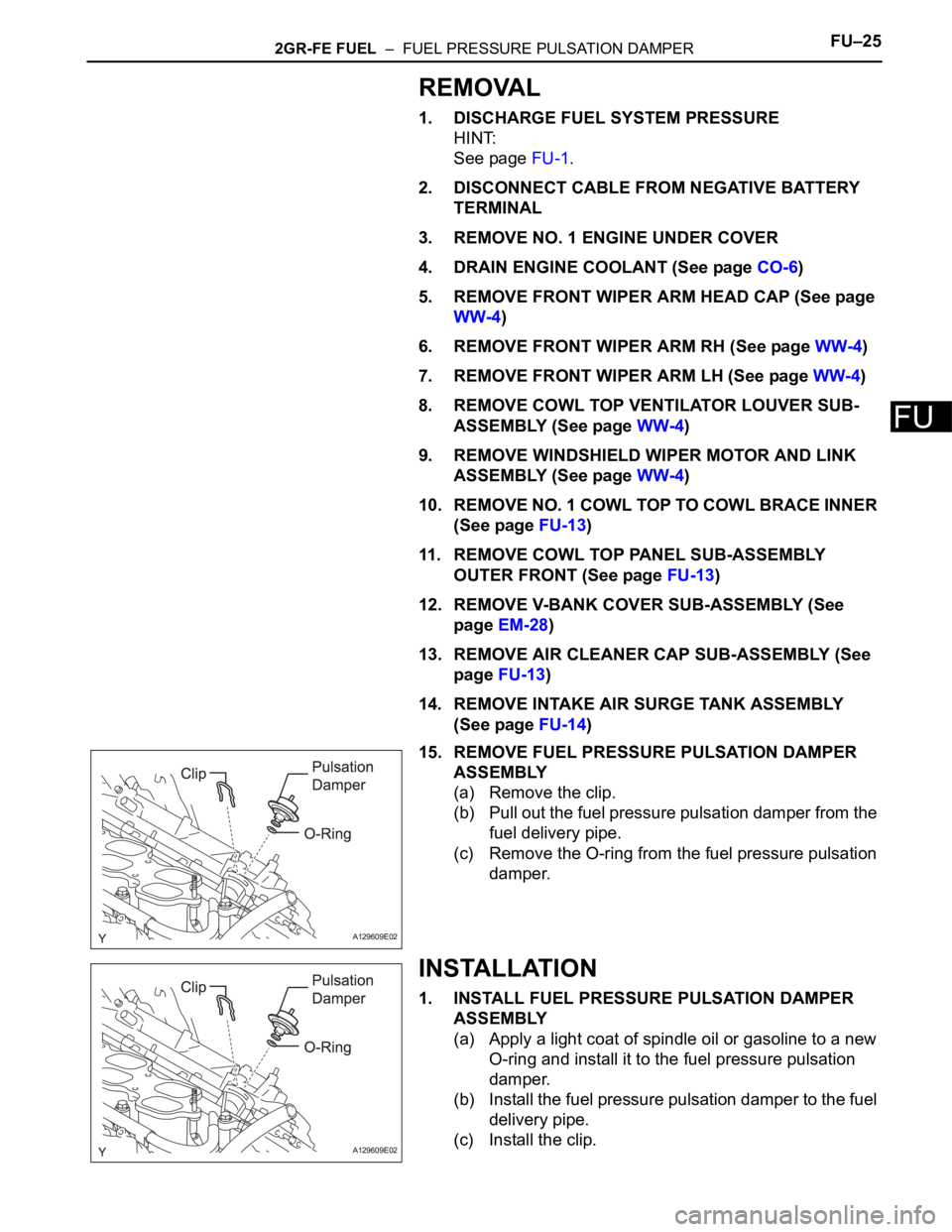
(a) Remove the clip.
(b) Pull out the fuel pressure pulsation damper from the
fuel delivery pipe.
(c) Remove the O-ring from the fuel pressure pulsation
damper.
INSTALLATION
1. INSTALL FUEL PRESSURE PULSATION DAMPER
ASSEMBLY
(a) Apply a light coat of spindle oil or gasoline to a new
O-ring and install it to the fuel pressure pulsation
damper.
(b) Install the fuel pressure pulsation damper to the fuel
delivery pipe.
(c) Install the clip.
A129609E02
A129609E02
Page 1144 of 3000
FU–262GR-FE FUEL – FUEL PRESSURE PULSATION DAMPER
FU
2. INSTALL INTAKE AIR SURGE TANK ASSEMBLY (See
page FU-19)
3. INSTALL AIR CLEANER CAP SUB-ASSEMBLY (See
page FU-20)
4. ADD ENGINE COOLANT (See page CO-7)
5. CONNECT CABLE TO NEGATIVE BATTERY
TERMINAL
6. INSPECT FOR ENGINE COOLANT LEAK (See page
CO-1)
7. INSTALL NO. 1 ENGINE UNDER COVER
8. INSPECT FOR FUEL LEAK (See page FU-7)
9. INSTALL V-BANK COVER SUB-ASSEMBLY (See
page EM-63)
10. INSTALL COWL TOP PANEL SUB-ASSEMBLY
OUTER FRONT (See page FU-21)
11. INSTALL NO. 1 COWL TOP TO COWL BRACE INNER
(See page FU-21)
12. INSTALL WINDSHIELD WIPER MOTOR AND LINK
ASSEMBLY (See page WW-6)
13. INSTALL FRONT WIPER ARM LH (See page WW-6)
14. INSTALL FRONT WIPER ARM RH (See page WW-7)
Page 1175 of 3000

2GR-FE EMISSION CONTROL – EMISSION CONTROL SYSTEMEC–5
EC
ON-VEHICLE INSPECTION
1. INSPECT FUEL CUT RPM
(a) Increase the engine speed to at least 3500 rpm.
(b) Use a sound scope to check for injector operating
sounds.
(c) Check that when the throttle lever is released,
injector operating sounds stop momentarily (at 2500
rpm) and then resume (at 1400 rpm).
Standard
2. CHECK AIR TIGHTNESS IN FUEL TANK AND FILLER
PIPE
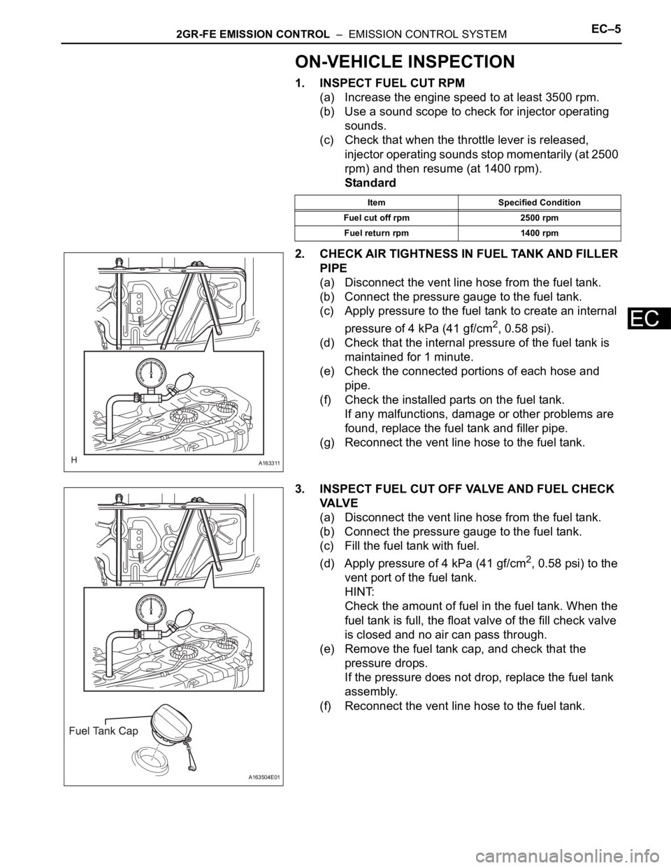
(a) Disconnect the vent line hose from the fuel tank.
(b) Connect the pressure gauge to the fuel tank.
(c) Apply pressure to the fuel tank to create an internal
pressure of 4 kPa (41 gf/cm
2, 0.58 psi).
(d) Check that the internal pressure of the fuel tank is
maintained for 1 minute.
(e) Check the connected portions of each hose and
pipe.
(f) Check the installed parts on the fuel tank.
If any malfunctions, damage or other problems are
found, replace the fuel tank and filler pipe.
(g) Reconnect the vent line hose to the fuel tank.
3. INSPECT FUEL CUT OFF VALVE AND FUEL CHECK
VA LV E
(a) Disconnect the vent line hose from the fuel tank.
(b) Connect the pressure gauge to the fuel tank.
(c) Fill the fuel tank with fuel.
(d) Apply pressure of 4 kPa (41 gf/cm
2, 0.58 psi) to the
vent port of the fuel tank.
HINT:
Check the amount of fuel in the fuel tank. When the
fuel tank is full, the float valve of the fill check valve
is closed and no air can pass through.
(e) Remove the fuel tank cap, and check that the
pressure drops.
If the pressure does not drop, replace the fuel tank
assembly.
(f) Reconnect the vent line hose to the fuel tank.
Item Specified Condition
Fuel cut off rpm 2500 rpm
Fuel return rpm 1400 rpm
A163311
A163504E01