Page 168 of 3000
SUSPENSION – SUSPENSION SYSTEMSP–3
SP
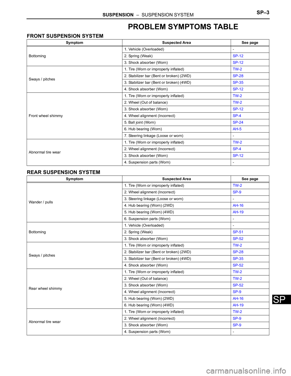
PROBLEM SYMPTOMS TABLE
FRONT SUSPENSION SYSTEM
REAR SUSPENSION SYSTEM
Symptom Suspected Area See page
Bottoming1. Vehicle (Overloaded) -
2. Spring (Weak)SP-12
3. Shock absorber (Worn)SP-12
Sways / pitches1. Tire (Worn or improperly inflated)TW-2
2. Stabilizer bar (Bent or broken) (2WD)SP-28
3. Stabilizer bar (Bent or broken) (4WD)SP-35
4. Shock absorber (Worn)SP-12
Front wheel shimmy1. Tire (Worn or improperly inflated)TW-2
2. Wheel (Out of balance)TW-2
3. Shock absorber (Worn)SP-12
4. Wheel alignment (Incorrect)SP-4
5. Ball joint (Worn)SP-24
6. Hub bearing (Worn)AH-5
7. Steering linkage (Loose or worn) -
Abnormal tire wear1. Tire (Worn or improperly inflated)TW-2
2. Wheel alignment (Incorrect)SP-4
3. Shock absorber (Worn)SP-12
4. Suspension parts (Worn) -
Symptom Suspected Area See page
Wander / pulls1. Tire (Worn or improperly inflated)TW-2
2. Wheel alignment (Incorrect)SP-9
3. Steering linkage (Loose or worn) -
4. Hub bearing (Worn) (2WD)AH-16
5. Hub bearing (Worn) (4WD)AH-19
6. Suspension parts (Worn) -
Bottoming1. Vehicle (Overloaded) -
2. Spring (Weak)SP-51
3. Shock absorber (Worn)SP-52
Sways / pitches1. Tire (Worn or improperly inflated)TW-2
2. Stabilizer bar (Bent or broken) (2WD)SP-28
3. Stabilizer bar (Bent or broken) (4WD)SP-35
4. Shock absorber (Worn)SP-52
Rear wheel shimmy1. Tire (Worn or improperly inflated)TW-2
2. Wheel (Out of balance)TW-2
3. Shock absorber (Worn)SP-52
4. Wheel alignment (Incorrect)SP-9
5. Hub bearing (Worn) (2WD)AH-16
6. Hub bearing (Worn) (4WD)AH-19
Abnormal tire wear1. Tire (Worn or improperly inflated)TW-2
2. Wheel alignment (Incorrect)SP-9
3. Shock absorber (Worn)SP-9
4. Suspension parts (Worn) -
Page 174 of 3000
TW–4TIRE AND WHEEL – TIRE AND WHEEL SYSTEM
TW
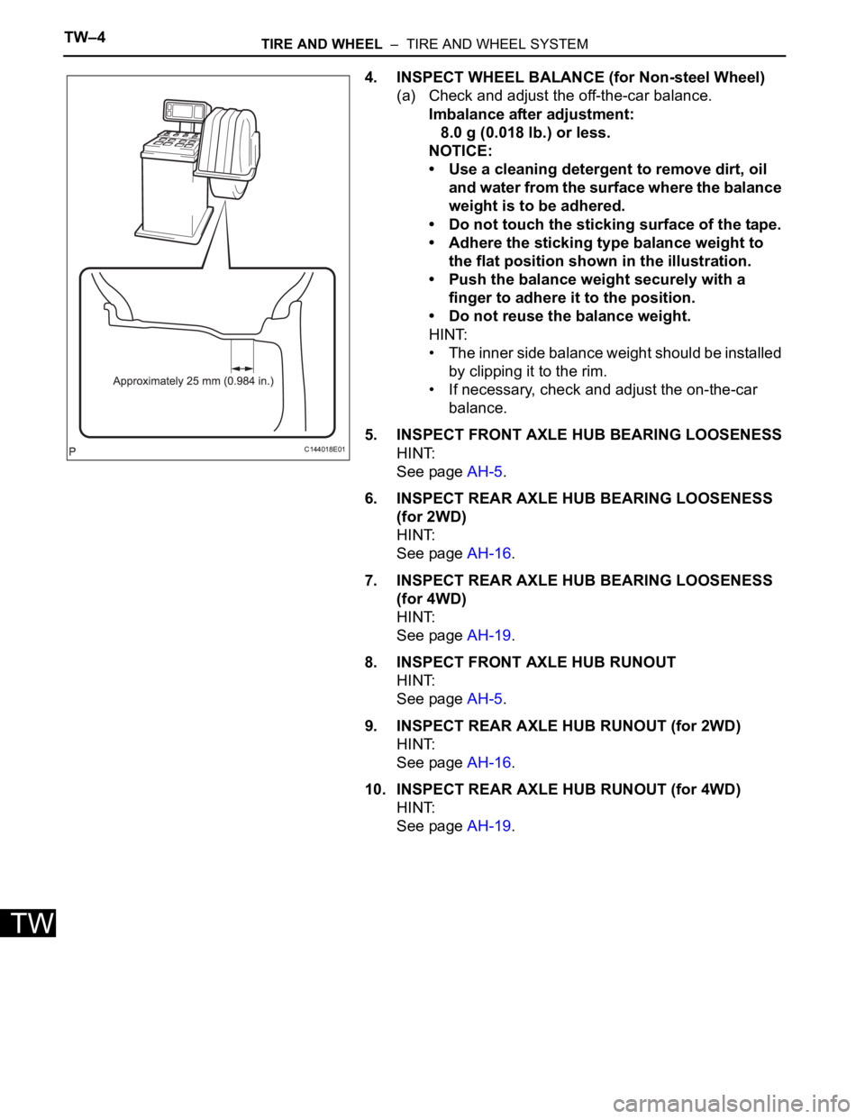
4. INSPECT WHEEL BALANCE (for Non-steel Wheel)
(a) Check and adjust the off-the-car balance.
Imbalance after adjustment:
8.0 g (0.018 lb.) or less.
NOTICE:
• Use a cleaning detergent to remove dirt, oil
and water from the surface where the balance
weight is to be adhered.
• Do not touch the sticking surface of the tape.
• Adhere the sticking type balance weight to
the flat position shown in the illustration.
• Push the balance weight securely with a
finger to adhere it to the position.
• Do not reuse the balance weight.
HINT:
• The inner side balance weight should be installed
by clipping it to the rim.
• If necessary, check and adjust the on-the-car
balance.
5. INSPECT FRONT AXLE HUB BEARING LOOSENESS
HINT:
See page AH-5.
6. INSPECT REAR AXLE HUB BEARING LOOSENESS
(for 2WD)
HINT:
See page AH-16.
7. INSPECT REAR AXLE HUB BEARING LOOSENESS
(for 4WD)
HINT:
See page AH-19.
8. INSPECT FRONT AXLE HUB RUNOUT
HINT:
See page AH-5.
9. INSPECT REAR AXLE HUB RUNOUT (for 2WD)
HINT:
See page AH-16.
10. INSPECT REAR AXLE HUB RUNOUT (for 4WD)
HINT:
See page AH-19.
C144018E01
Page 870 of 3000
2GR-FE ENGINE MECHANICAL – ENGINE ASSEMBLYEM–53
EM
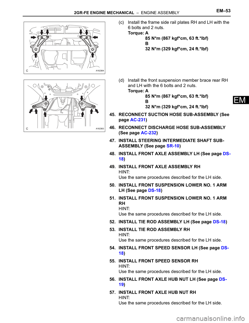
(c) Install the frame side rail plates RH and LH with the
6 bolts and 2 nuts.
Torque: A
85 N*m (867 kgf*cm, 63 ft.*lbf)
B
32 N*m (329 kgf*cm, 24 ft.*lbf)
(d) Install the front suspension member brace rear RH
and LH with the 6 bolts and 2 nuts.
Torque: A
85 N*m (867 kgf*cm, 63 ft.*lbf)
B
32 N*m (329 kgf*cm, 24 ft.*lbf)
45. RECONNECT SUCTION HOSE SUB-ASSEMBLY (See
page AC-231)
46. RECONNECT DISCHARGE HOSE SUB-ASSEMBLY
(See page AC-232)
47. INSTALL STEERING INTERMEDIATE SHAFT SUB-
ASSEMBLY (See page SR-10)
48. INSTALL FRONT AXLE ASSEMBLY LH (See page DS-
18)
49. INSTALL FRONT AXLE ASSEMBLY RH
HINT:
Use the same procedures described for the LH side.
50. INSTALL FRONT SUSPENSION LOWER NO. 1 ARM
LH (See page DS-18)
51. INSTALL FRONT SUSPENSION LOWER NO. 1 ARM
RH
HINT:
Use the same procedures described for the LH side.
52. INSTALL TIE ROD ASSEMBLY LH (See page DS-18)
53. INSTALL TIE ROD ASSEMBLY RH
HINT:
Use the same procedures described for the LH side.
54. INSTALL FRONT SPEED SENSOR LH (See page DS-
18)
55. INSTALL FRONT SPEED SENSOR RH
HINT:
Use the same procedures described for the LH side.
56. INSTALL FRONT AXLE HUB NUT LH (See page DS-
19)
57. INSTALL FRONT AXLE HUB NUT RH
HINT:
Use the same procedures described for the LH side.
A162364
A162363
Page 1012 of 3000
2GR-FE ENGINE MECHANICAL – ENGINE ASSEMBLYEM–53
EM
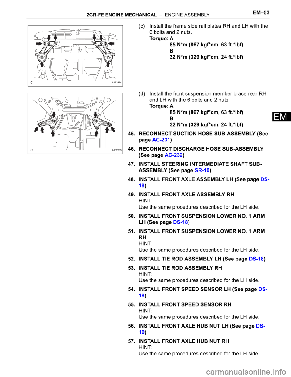
(c) Install the frame side rail plates RH and LH with the
6 bolts and 2 nuts.
Torque: A
85 N*m (867 kgf*cm, 63 ft.*lbf)
B
32 N*m (329 kgf*cm, 24 ft.*lbf)
(d) Install the front suspension member brace rear RH
and LH with the 6 bolts and 2 nuts.
Torque: A
85 N*m (867 kgf*cm, 63 ft.*lbf)
B
32 N*m (329 kgf*cm, 24 ft.*lbf)
45. RECONNECT SUCTION HOSE SUB-ASSEMBLY (See
page AC-231)
46. RECONNECT DISCHARGE HOSE SUB-ASSEMBLY
(See page AC-232)
47. INSTALL STEERING INTERMEDIATE SHAFT SUB-
ASSEMBLY (See page SR-10)
48. INSTALL FRONT AXLE ASSEMBLY LH (See page DS-
18)
49. INSTALL FRONT AXLE ASSEMBLY RH
HINT:
Use the same procedures described for the LH side.
50. INSTALL FRONT SUSPENSION LOWER NO. 1 ARM
LH (See page DS-18)
51. INSTALL FRONT SUSPENSION LOWER NO. 1 ARM
RH
HINT:
Use the same procedures described for the LH side.
52. INSTALL TIE ROD ASSEMBLY LH (See page DS-18)
53. INSTALL TIE ROD ASSEMBLY RH
HINT:
Use the same procedures described for the LH side.
54. INSTALL FRONT SPEED SENSOR LH (See page DS-
18)
55. INSTALL FRONT SPEED SENSOR RH
HINT:
Use the same procedures described for the LH side.
56. INSTALL FRONT AXLE HUB NUT LH (See page DS-
19)
57. INSTALL FRONT AXLE HUB NUT RH
HINT:
Use the same procedures described for the LH side.
A162364
A162363
Page 1568 of 3000
U151E AUTOMATIC TRANSAXLE – AUTOMATIC TRANSAXLE UNITAX–189
AX
48. REMOVE GOVERNOR APPLY GASKET NO.1
(a) Using a screwdriver, remove the 3 apply gaskets.
49. REMOVE BRAKE APPLY TUBE
(a) Remove the bolt, clamp and brake apply tube.
(b) Remove the clutch apply tube.
(c) Remove the brake apply tube from the clamp.
NOTICE:
Do not bend the tubes.
50. REMOVE DIRECT CLUTCH ASSEMBLY
(a) Remove the thrust bearing and the direct clutch
assembly from the transaxle case.
51. REMOVE OVERDRIVE DIRECT CLUTCH HUB SUB-
ASSEMBLY
(a) Remove the thrust bearing race, thrust bearing and
overdrive direct clutch hub from the planetary gear
assembly.
52. INSPECT OVERDRIVE DIRECT CLUTCH DRUM SUB-
ASSEMBLY
HINT:
(See page AX-198)
53. REMOVE REAR PLANETARY SUN GEAR ASSEMBLY
(a) Remove the rear planetary sun gear assembly from
the transaxle case.
D026390
D026391E03
D026403E02
D026392E03
D026714E02
Page 1595 of 3000
U151E AUTOMATIC TRANSAXLE – AUTOMATIC TRANSAXLE UNITAX–209
AX
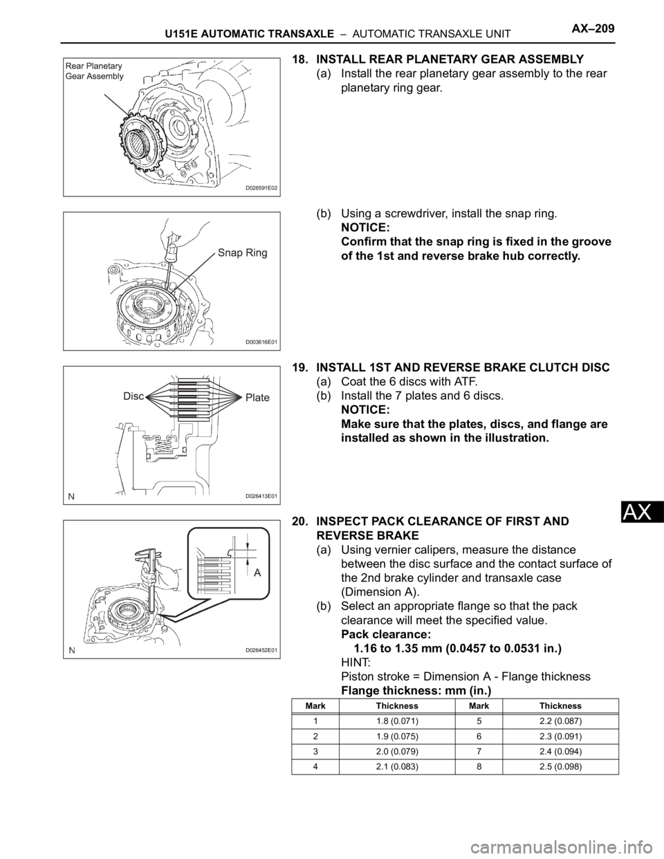
18. INSTALL REAR PLANETARY GEAR ASSEMBLY
(a) Install the rear planetary gear assembly to the rear
planetary ring gear.
(b) Using a screwdriver, install the snap ring.
NOTICE:
Confirm that the snap ring is fixed in the groove
of the 1st and reverse brake hub correctly.
19. INSTALL 1ST AND REVERSE BRAKE CLUTCH DISC
(a) Coat the 6 discs with ATF.
(b) Install the 7 plates and 6 discs.
NOTICE:
Make sure that the plates, discs, and flange are
installed as shown in the illustration.
20. INSPECT PACK CLEARANCE OF FIRST AND
REVERSE BRAKE
(a) Using vernier calipers, measure the distance
between the disc surface and the contact surface of
the 2nd brake cylinder and transaxle case
(Dimension A).
(b) Select an appropriate flange so that the pack
clearance will meet the specified value.
Pack clearance:
1.16 to 1.35 mm (0.0457 to 0.0531 in.)
HINT:
Piston stroke = Dimension A - Flange thickness
Flange thickness: mm (in.)
D026591E02
D003616E01
D026413E01
D026452E01
Mark Thickness Mark Thickness
1 1.8 (0.071) 5 2.2 (0.087)
2 1.9 (0.075) 6 2.3 (0.091)
3 2.0 (0.079) 7 2.4 (0.094)
4 2.1 (0.083) 8 2.5 (0.098)
Page 1599 of 3000
U151E AUTOMATIC TRANSAXLE – AUTOMATIC TRANSAXLE UNITAX–213
AX
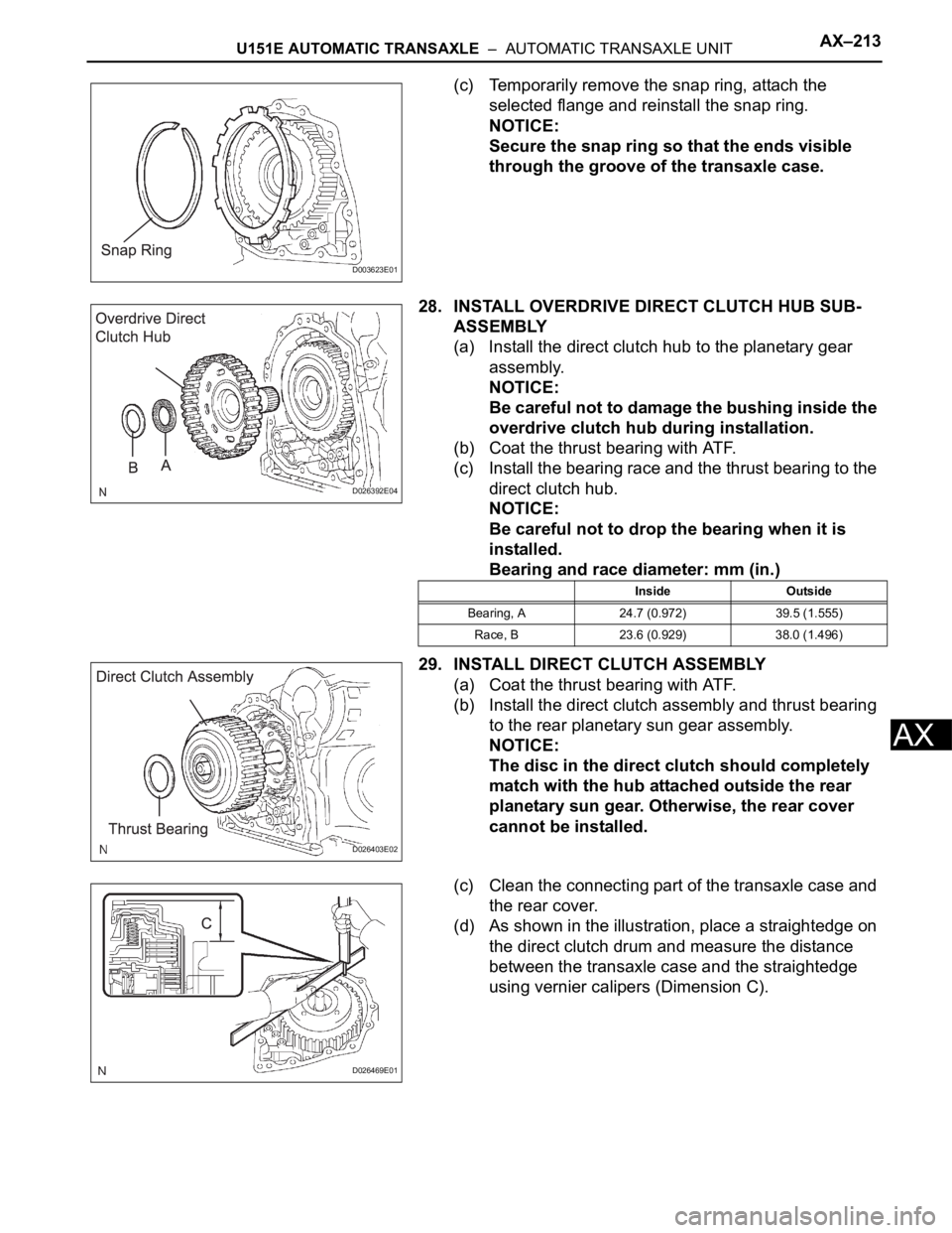
(c) Temporarily remove the snap ring, attach the
selected flange and reinstall the snap ring.
NOTICE:
Secure the snap ring so that the ends visible
through the groove of the transaxle case.
28. INSTALL OVERDRIVE DIRECT CLUTCH HUB SUB-
ASSEMBLY
(a) Install the direct clutch hub to the planetary gear
assembly.
NOTICE:
Be careful not to damage the bushing inside the
overdrive clutch hub during installation.
(b) Coat the thrust bearing with ATF.
(c) Install the bearing race and the thrust bearing to the
direct clutch hub.
NOTICE:
Be careful not to drop the bearing when it is
installed.
Bearing and race diameter: mm (in.)
29. INSTALL DIRECT CLUTCH ASSEMBLY
(a) Coat the thrust bearing with ATF.
(b) Install the direct clutch assembly and thrust bearing
to the rear planetary sun gear assembly.
NOTICE:
The disc in the direct clutch should completely
match with the hub attached outside the rear
planetary sun gear. Otherwise, the rear cover
cannot be installed.
(c) Clean the connecting part of the transaxle case and
the rear cover.
(d) As shown in the illustration, place a straightedge on
the direct clutch drum and measure the distance
between the transaxle case and the straightedge
using vernier calipers (Dimension C).
D003623E01
D026392E04
Inside Outside
Bearing, A 24.7 (0.972) 39.5 (1.555)
Race, B 23.6 (0.929) 38.0 (1.496)
D026403E02
D026469E01
Page 1633 of 3000
U151E AUTOMATIC TRANSAXLE – AUTOMATIC TRANSAXLE UNITAX–189
AX
48. REMOVE GOVERNOR APPLY GASKET NO.1
(a) Using a screwdriver, remove the 3 apply gaskets.
49. REMOVE BRAKE APPLY TUBE
(a) Remove the bolt, clamp and brake apply tube.
(b) Remove the clutch apply tube.
(c) Remove the brake apply tube from the clamp.
NOTICE:
Do not bend the tubes.
50. REMOVE DIRECT CLUTCH ASSEMBLY
(a) Remove the thrust bearing and the direct clutch
assembly from the transaxle case.
51. REMOVE OVERDRIVE DIRECT CLUTCH HUB SUB-
ASSEMBLY
(a) Remove the thrust bearing race, thrust bearing and
overdrive direct clutch hub from the planetary gear
assembly.
52. INSPECT OVERDRIVE DIRECT CLUTCH DRUM SUB-
ASSEMBLY
HINT:
(See page AX-198)
53. REMOVE REAR PLANETARY SUN GEAR ASSEMBLY
(a) Remove the rear planetary sun gear assembly from
the transaxle case.
D026390
D026391E03
D026403E02
D026392E03
D026714E02