2007 TOYOTA SIENNA fuel injector
[x] Cancel search: fuel injectorPage 44 of 3000
2GR-FE EMISSION CONTROL – EMISSION CONTROL SYSTEMEC–5
EC
ON-VEHICLE INSPECTION
1. INSPECT FUEL CUT RPM
(a) Increase the engine speed to at least 3500 rpm.
(b) Use a sound scope to check for injector operating
sounds.
(c) Check that when the throttle lever is released,
injector operating sounds stop momentarily (at 2500
rpm) and then resume (at 1400 rpm).
Standard
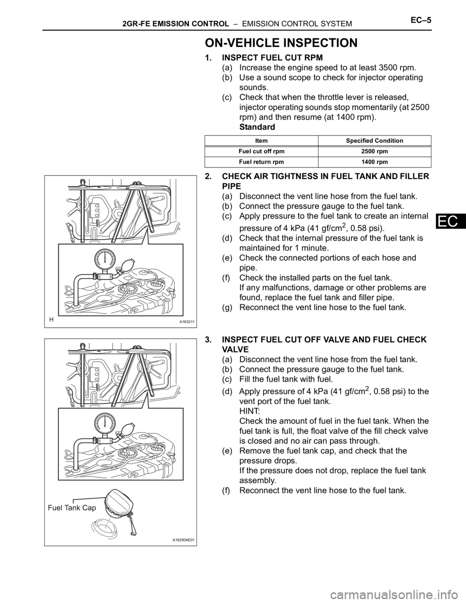
2. CHECK AIR TIGHTNESS IN FUEL TANK AND FILLER
PIPE
(a) Disconnect the vent line hose from the fuel tank.
(b) Connect the pressure gauge to the fuel tank.
(c) Apply pressure to the fuel tank to create an internal
pressure of 4 kPa (41 gf/cm
2, 0.58 psi).
(d) Check that the internal pressure of the fuel tank is
maintained for 1 minute.
(e) Check the connected portions of each hose and
pipe.
(f) Check the installed parts on the fuel tank.
If any malfunctions, damage or other problems are
found, replace the fuel tank and filler pipe.
(g) Reconnect the vent line hose to the fuel tank.
3. INSPECT FUEL CUT OFF VALVE AND FUEL CHECK
VA LV E
(a) Disconnect the vent line hose from the fuel tank.
(b) Connect the pressure gauge to the fuel tank.
(c) Fill the fuel tank with fuel.
(d) Apply pressure of 4 kPa (41 gf/cm
2, 0.58 psi) to the
vent port of the fuel tank.
HINT:
Check the amount of fuel in the fuel tank. When the
fuel tank is full, the float valve of the fill check valve
is closed and no air can pass through.
(e) Remove the fuel tank cap, and check that the
pressure drops.
If the pressure does not drop, replace the fuel tank
assembly.
(f) Reconnect the vent line hose to the fuel tank.
Item Specified Condition
Fuel cut off rpm 2500 rpm
Fuel return rpm 1400 rpm
A163311
A163504E01
Page 80 of 3000

IG–62GR-FE IGNITION – IGNITION COIL AND SPARK PLUG
IG
ON-VEHICLE INSPECTION
NOTICE:
In this section, the terms "cold" and "hot" refer to the
temperature of the coils. "Cold" means approximately -
10
C (14F) to 50C (122F). "Hot" means approximately
50
C (122F) to 100C (212F).
1. INSPECT IGNITION COIL ASSEMBLY
(a) Check for DTCs.
NOTICE:
If any DTC is present, perform troubleshooting
in accordance with the procedures for that DTC.
(b) Remove the ignition coil assembly and spark plug.
(See page IG-8).
(c) Check that sparks occur.
(1) Disconnect the 6 fuel injector connectors.
(2) Install the spark plugs to each ignition coil, and
connect the ignition coil connectors.
(3) Ground the spark plugs.
(4) Check if a spark occurs at each spark plug
while the engine is being cranked.
NOTICE:
• Be sure to ground the spark plugs when
checking.
• Replace the ignition coil if it receives an
impact.
• Do not crank the engine for more than 2
seconds.
(d) Perform the spark test according to the flowchart
below.
(1) Check that the ignition coil connector is
securely connected.
Result
(2) Perform a spark test on each ignition coil.
1. Replace the ignition coil with a normal one.
2. Perform the spark test again.
Result
A133895
A133897
Result Proceed to
NG Connect securely
OK Go to next step
Result Proceed to
NG Go to next step
OK Replace ignition coil
Page 81 of 3000

2GR-FE IGNITION – IGNITION COIL AND SPARK PLUGIG–7
IG
(3) Check the spark plug (See page EM-1).
Result
(4) Check the power supply to the ignition coil.
1. Turn the ignition switch to the ON position.
2. Check that there is battery voltage at the
ignition coil positive (+) terminal.
Result
(5) Measure the resistance of the crankshaft
position sensor (See page ES-514).
Result
(6) Check the IGT signal from the ECM (See page
ES-233)
Result
(e) Using a 16 mm (0.63 in.) plug wrench, install the
spark plugs.
Torque: 18 N*m (184 kgf*cm, 13 ft.*lbf)
(f) Connect the 6 fuel injector connectors.
(g) Install the ignition coil assembly (See page IG-10).
2. INSPECT SPARK PLUG
NOTICE:
• Never use a wire brush for cleaning.
• Never attempt to adjust the electrode gap on a
used spark plug.
(a) Check the electrode.
(1) Using a megohmmeter, measure the insulation
resistance.
Standard insulation resistance:
10 M
or higher
HINT:
• If the result is 10 M
or less, clean the plug
and measure the resistance again.
• If a megohmmeter is not available, perform
the following simple inspection instead.
(b) Alternative inspection method:
(1) Quickly accelerate the engine to 4000 rpm 5
times.
Result Proceed to
NG Replace spark plug
OK Go to next step
Result Proceed to
NGCheck wiring between ignition
switch and ignition coil
OK Go to next step
Result Proceed to
NG Replace crankshaft position sensor
OK Go to next step
Result Proceed to
NG Check ECM
OKRepair wiring between ignition coil
and ECM
I039522E10
Page 357 of 3000
2GR-FE ENGINE CONTROL SYSTEM – SFI SYSTEMES–31
ES
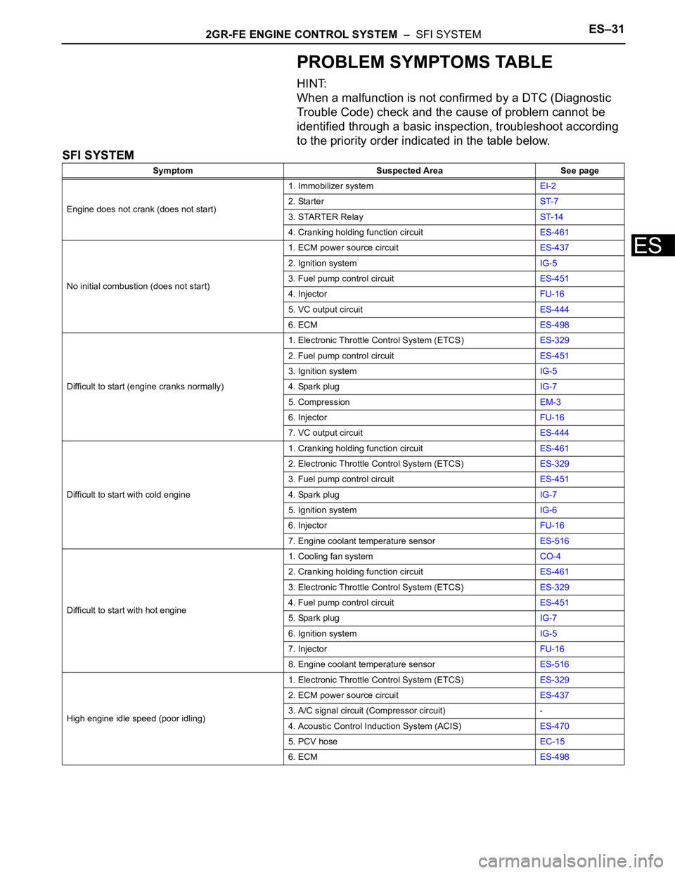
PROBLEM SYMPTOMS TABLE
HINT:
When a malfunction is not confirmed by a DTC (Diagnostic
Trouble Code) check and the cause of problem cannot be
identified through a basic inspection, troubleshoot according
to the priority order indicated in the table below.
SFI SYSTEM
Symptom Suspected Area See page
Engine does not crank (does not start)1. Immobilizer systemEI-2
2. StarterST-7
3. STARTER RelayST-14
4. Cranking holding function circuitES-461
No initial combustion (does not start)1. ECM power source circuitES-437
2. Ignition systemIG-5
3. Fuel pump control circuitES-451
4. InjectorFU-16
5. VC output circuitES-444
6. ECMES-498
Difficult to start (engine cranks normally)1. Electronic Throttle Control System (ETCS)ES-329
2. Fuel pump control circuitES-451
3. Ignition systemIG-5
4. Spark plugIG-7
5. CompressionEM-3
6. InjectorFU-16
7. VC output circuitES-444
Difficult to start with cold engine1. Cranking holding function circuitES-461
2. Electronic Throttle Control System (ETCS)ES-329
3. Fuel pump control circuitES-451
4. Spark plugIG-7
5. Ignition systemIG-6
6. InjectorFU-16
7. Engine coolant temperature sensorES-516
Difficult to start with hot engine1. Cooling fan systemCO-4
2. Cranking holding function circuitES-461
3. Electronic Throttle Control System (ETCS)ES-329
4. Fuel pump control circuitES-451
5. Spark plugIG-7
6. Ignition systemIG-5
7. InjectorFU-16
8. Engine coolant temperature sensorES-516
High engine idle speed (poor idling)1. Electronic Throttle Control System (ETCS)ES-329
2. ECM power source circuitES-437
3. A/C signal circuit (Compressor circuit) -
4. Acoustic Control Induction System (ACIS)ES-470
5. PCV hoseEC-15
6. ECMES-498
Page 358 of 3000
ES–322GR-FE ENGINE CONTROL SYSTEM – SFI SYSTEM
ES
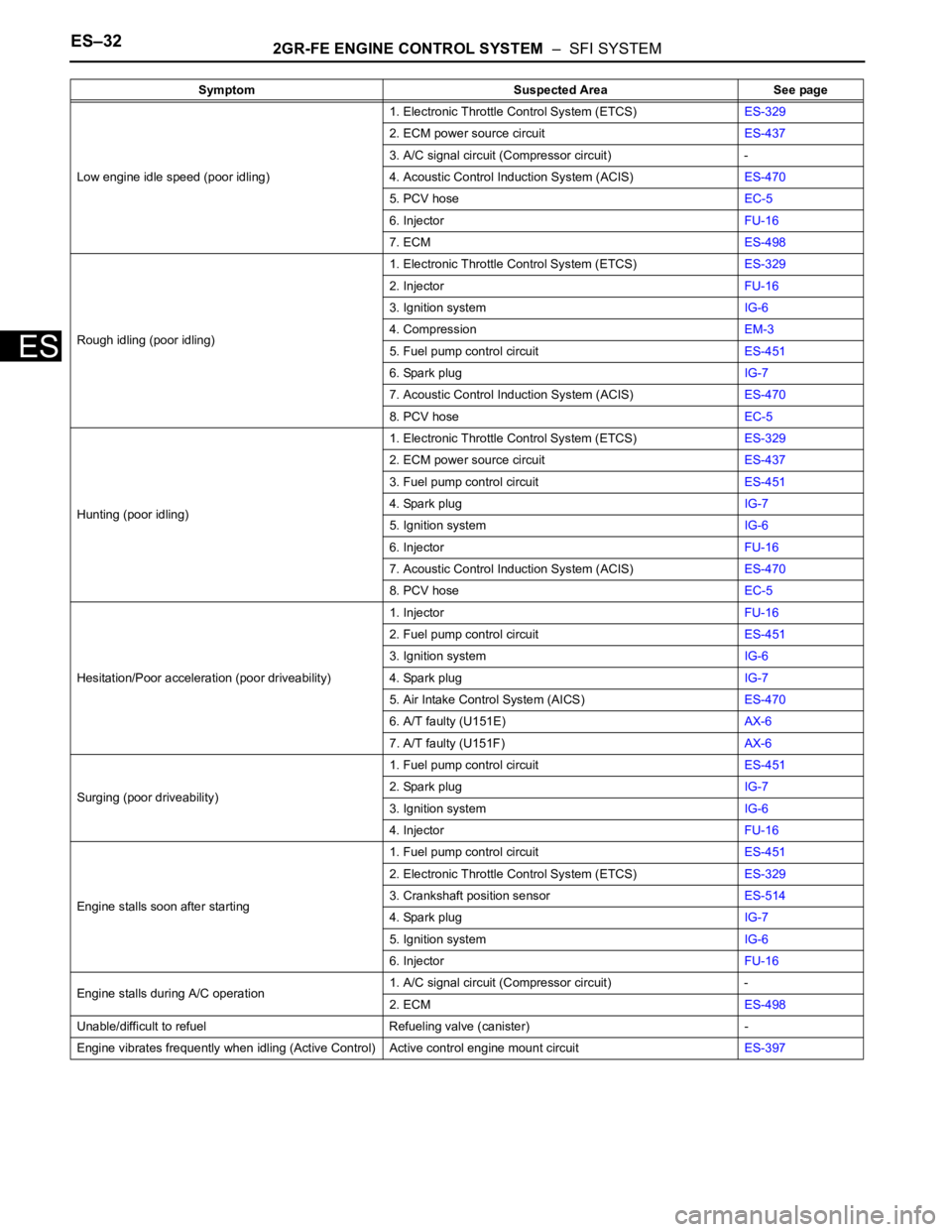
Low engine idle speed (poor idling)1. Electronic Throttle Control System (ETCS)ES-329
2. ECM power source circuitES-437
3. A/C signal circuit (Compressor circuit) -
4. Acoustic Control Induction System (ACIS)ES-470
5. PCV hoseEC-5
6. InjectorFU-16
7. ECMES-498
Rough idling (poor idling)1. Electronic Throttle Control System (ETCS)ES-329
2. InjectorFU-16
3. Ignition systemIG-6
4. CompressionEM-3
5. Fuel pump control circuitES-451
6. Spark plugIG-7
7. Acoustic Control Induction System (ACIS)ES-470
8. PCV hoseEC-5
Hunting (poor idling)1. Electronic Throttle Control System (ETCS)ES-329
2. ECM power source circuitES-437
3. Fuel pump control circuitES-451
4. Spark plugIG-7
5. Ignition systemIG-6
6. InjectorFU-16
7. Acoustic Control Induction System (ACIS)ES-470
8. PCV hoseEC-5
Hesitation/Poor acceleration (poor driveability)1. InjectorFU-16
2. Fuel pump control circuitES-451
3. Ignition systemIG-6
4. Spark plugIG-7
5. Air Intake Control System (AICS)ES-470
6. A/T faulty (U151E)AX-6
7. A/T faulty (U151F)AX-6
Surging (poor driveability)1. Fuel pump control circuitES-451
2. Spark plugIG-7
3. Ignition systemIG-6
4. InjectorFU-16
Engine stalls soon after starting1. Fuel pump control circuitES-451
2. Electronic Throttle Control System (ETCS)ES-329
3. Crankshaft position sensorES-514
4. Spark plugIG-7
5. Ignition systemIG-6
6. InjectorFU-16
Engine stalls during A/C operation1. A/C signal circuit (Compressor circuit) -
2. ECMES-498
Unable/difficult to refuel Refueling valve (canister) -
Engine vibrates frequently when idling (Active Control) Active control engine mount circuitES-397 Symptom Suspected Area See page
Page 364 of 3000
ES–462GR-FE ENGINE CONTROL SYSTEM – SFI SYSTEM
ES
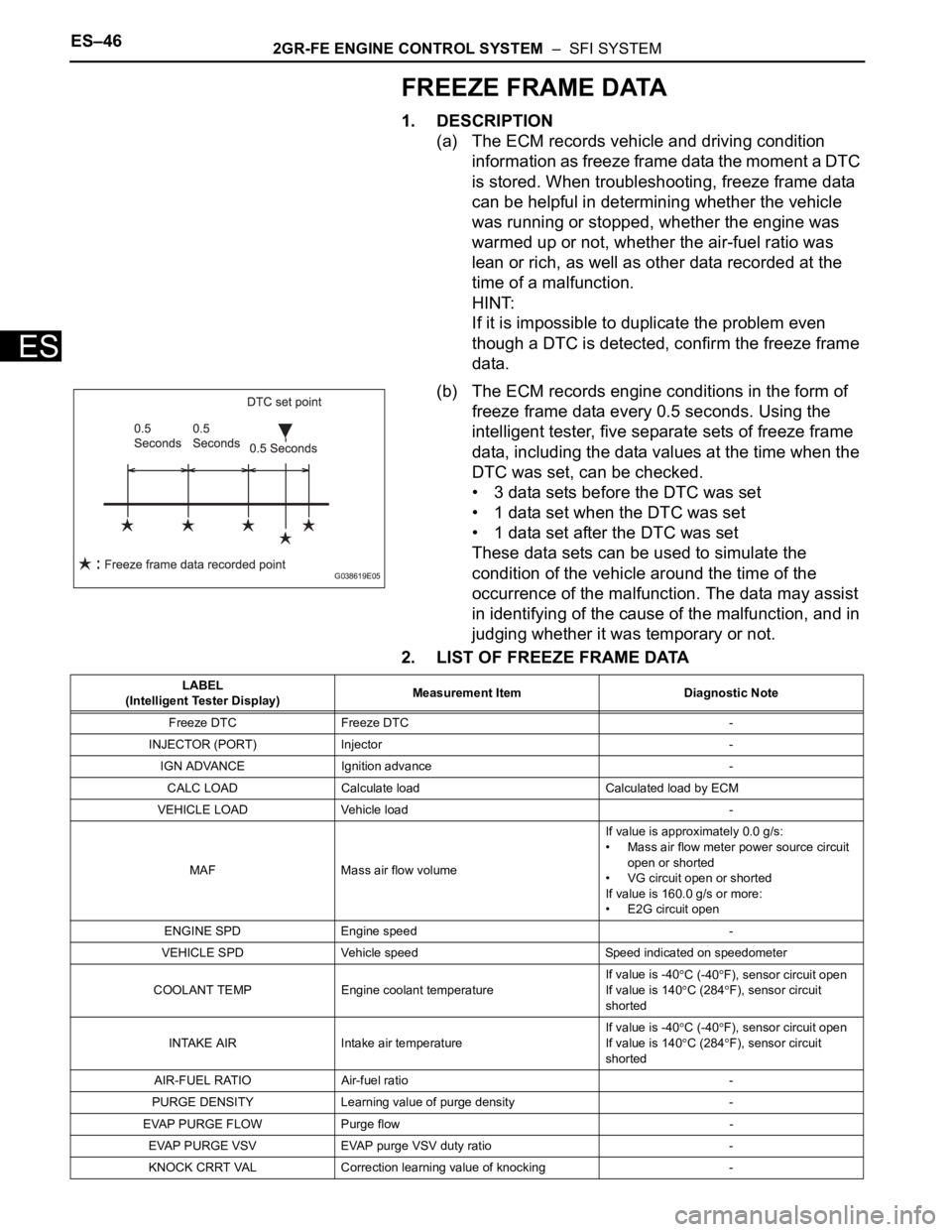
FREEZE FRAME DATA
1. DESCRIPTION
(a) The ECM records vehicle and driving condition
information as freeze frame data the moment a DTC
is stored. When troubleshooting, freeze frame data
can be helpful in determining whether the vehicle
was running or stopped, whether the engine was
warmed up or not, whether the air-fuel ratio was
lean or rich, as well as other data recorded at the
time of a malfunction.
HINT:
If it is impossible to duplicate the problem even
though a DTC is detected, confirm the freeze frame
data.
(b) The ECM records engine conditions in the form of
freeze frame data every 0.5 seconds. Using the
intelligent tester, five separate sets of freeze frame
data, including the data values at the time when the
DTC was set, can be checked.
• 3 data sets before the DTC was set
• 1 data set when the DTC was set
• 1 data set after the DTC was set
These data sets can be used to simulate the
condition of the vehicle around the time of the
occurrence of the malfunction. The data may assist
in identifying of the cause of the malfunction, and in
judging whether it was temporary or not.
2. LIST OF FREEZE FRAME DATA
G038619E05
LABEL
(Intelligent Tester Display)Measurement Item Diagnostic Note
Freeze DTC Freeze DTC -
INJECTOR (PORT) Injector -
IGN ADVANCE Ignition advance -
CALC LOAD Calculate load Calculated load by ECM
VEHICLE LOAD Vehicle load -
MAF Mass air flow volumeIf value is approximately 0.0 g/s:
• Mass air flow meter power source circuit
open or shorted
• VG circuit open or shorted
If value is 160.0 g/s or more:
• E2G circuit open
ENGINE SPD Engine speed -
VEHICLE SPD Vehicle speed Speed indicated on speedometer
COOLANT TEMP Engine coolant temperatureIf value is -40
C (-40F), sensor circuit open
If value is 140
C (284F), sensor circuit
shorted
INTAKE AIR Intake air temperatureIf value is -40
C (-40F), sensor circuit open
If value is 140C (284F), sensor circuit
shorted
AIR-FUEL RATIO Air-fuel ratio -
PURGE DENSITY Learning value of purge density -
EVAP PURGE FLOW Purge flow -
EVAP PURGE VSV EVAP purge VSV duty ratio -
KNOCK CRRT VAL Correction learning value of knocking -
Page 369 of 3000

2GR-FE ENGINE CONTROL SYSTEM – SFI SYSTEMES–51
ES
FAIL-SAFE CHART
If any of the following DTCs are set, the ECM enters fail-safe
mode to allow the vehicle to be driven temporarily.
HINT:
• *1: The vehicle can be driven slowly when the accelerator
pedal is depressed firmly and slowly. If the accelerator
pedal is depressed quickly, the vehicle may speed up and
slow down erratically.
• *2: Misfire related fail-safe operations occur when catalyst
overheat malfunctions occur.
DTCs Components Fail-Safe OperationsFail-Safe Deactivation
Conditions
P0031, P0032, P0051 and P0052Air-Fuel Ratio (A/F) Sensor
HeaterECM turns off A/F sensor heater Ignition switch off
P0037, P0038, P0057 and P0058Heated Oxygen (HO2) Sensor
HeaterECM turns off HO2 sensor heater Ignition switch off
P0100, P0102 and P0103 Mass Air Flow (MAF) MeterECM calculates ignition timing
according to engine speed and
throttle valve positionPass condition detected
P0110, P0112 and P0113Intake Air Temperature (IAT)
SensorECM estimates IAT to be 20
C
(68
F)Pass condition detected
P0115, P0117 and P0118Engine Coolant Temperature
(ECT) SensorECM estimates ECT to be 80
C
(176
F)Pass condition detected
P0120, P0121, P0122, P0123,
P0220, P0222, P0223, P0604,
P0606, P0607, P0657, P2102,
P2103, P2111, P2112, P2118,
P2119 and P2135Electronic Throttle Control
System (ETCS)ECM cuts off throttle actuator
current and throttle valve returned
to 6.5
throttle position by return
spring
ECM then adjusts engine output
by controlling fuel injection
(intermittent fuel-cut) and ignition
timing in accordance with
accelerator pedal opening angle,
to allow vehicle to continue at
minimal speed*1Pass condition detected and then
ignition switch turned off
P0300, P0301, P0302, P0303,
P0304, P0305 and P0306*2• Fuel injector
• Electronic Throttle Control
System (ETCS)When misfire occurs, fuel cut is
performed for catalyst overheat
malfunction prevention
• During normal load and
normal engine speed (MIL is
blinking)
- Fuel cut is performed on
malfunctioning cylinder
• During high load and high
engine speed (MIL is
blinking)
- Throttle valve opening angle
control is performed
- All cylinder fuel cut or
malfunction cylinder fuel cutPass condition detected and then
ignition switch turned OFF
P0327, P0328, P0332 and P0333 Knock SensorECM sets ignition timing to
maximum retardIgnition switch off
P0351 to P0356 Igniter ECM cuts fuel Pass condition detected
P2120, P2121, P2122, P2123,
P2125, P2127, P2128 and P2138Accelerator Pedal Position (APP)
SensorAPP sensor has 2 sensor circuits:
Main and Sub
If either of circuits malfunctions,
ECM controls engine using the
other circuit
If both of circuits malfunction,
ECM regards accelerator pedal
as being released. As a result,
throttle valve is closed and engine
idlesPass condition detected and then
ignition switch turned off
Page 375 of 3000
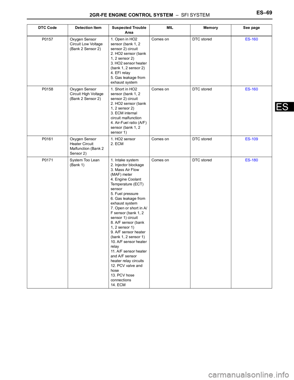
2GR-FE ENGINE CONTROL SYSTEM – SFI SYSTEMES–69
ES
P0157 Oxygen Sensor
Circuit Low Voltage
(Bank 2 Sensor 2)1. Open in HO2
sensor (bank 1, 2
sensor 2) circuit
2. HO2 sensor (bank
1, 2 sensor 2)
3. HO2 sensor heater
(bank 1, 2 sensor 2)
4. EFI relay
5. Gas leakage from
exhaust systemComes on DTC storedES-160
P0158 Oxygen Sensor
Circuit High Voltage
(Bank 2 Sensor 2)1. Short in HO2
sensor (bank 1, 2
sensor 2) circuit
2. HO2 sensor (bank
1, 2 sensor 2)
3. ECM internal
circuit malfunction
4. Air-Fuel ratio (A/F)
sensor (bank 1, 2
sensor 1)Comes on DTC storedES-160
P0161 Oxygen Sensor
Heater Circuit
Malfunction (Bank 2
Sensor 2)1. HO2 sensor
2. ECMComes on DTC storedES-109
P0171 System Too Lean
(Bank 1)1. Intake system
2. Injector blockage
3. Mass Air Flow
(MAF) meter
4. Engine Coolant
Temperature (ECT)
sensor
5. Fuel pressure
6. Gas leakage from
exhaust system
7. Open or short in A/
F sensor (bank 1, 2
sensor 1) circuit
8. A/F sensor (bank
1, 2 sensor 1)
9. A/F sensor heater
(bank 1, 2 sensor 1)
10. A/F sensor heater
relay
11. A/F sensor heater
and A/F sensor
heater relay circuits
12. PCV valve and
hose
13. PCV hose
connections
14. ECMComes on DTC storedES-180 DTC Code Detection Item Suspected Trouble
AreaMIL Memory See page