2007 TOYOTA SIENNA throttle body
[x] Cancel search: throttle bodyPage 21 of 3000
2GR-FE ENGINE CONTROL SYSTEM – KNOCK SENSORES–521
ES
REMOVAL
1. DISCHARGE FUEL SYSTEM PRESSURE
(See page FU-13)
2. REMOVE V-BANK COVER SUB-ASSEMBLY (See
page EM-28)
3. DRAIN ENGINE COOLANT (See page CO-6)
4. REMOVE WINDSHIELD WIPER MOTOR ASSEMBLY
HINT:
(See page WW-4)
5. REMOVE FRONT OUTER COWL TOP PANEL SUB-
ASSEMBLY (See page EM-27)
6. REMOVE AIR CLEANER CAP SUB-ASSEMBLY (See
page ES-493)
7. REMOVE AIR CLEANER CASE SUB-ASSEMBLY (See
page EM-28)
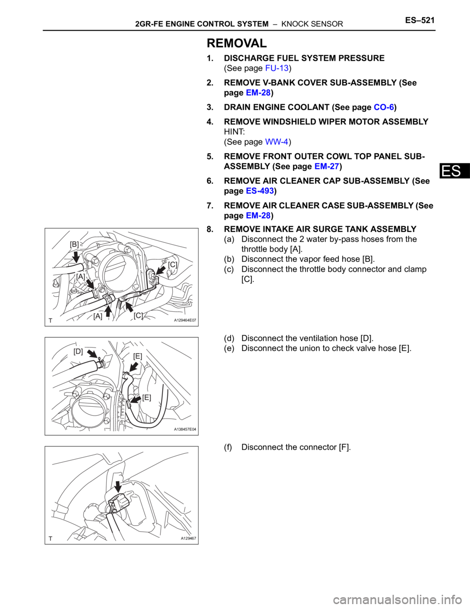
8. REMOVE INTAKE AIR SURGE TANK ASSEMBLY
(a) Disconnect the 2 water by-pass hoses from the
throttle body [A].
(b) Disconnect the vapor feed hose [B].
(c) Disconnect the throttle body connector and clamp
[C].
(d) Disconnect the ventilation hose [D].
(e) Disconnect the union to check valve hose [E].
(f) Disconnect the connector [F].
A129464E07
A138457E04
A129467
Page 22 of 3000
![TOYOTA SIENNA 2007 Service Repair Manual ES–5222GR-FE ENGINE CONTROL SYSTEM – KNOCK SENSOR
ES
(g) Using a 5 mm socket hexagon wrench, remove the
4 bolts [G].
(h) Remove the 2 nuts, 2 bolts and intake air surge tank
[H].
(i) Remove th TOYOTA SIENNA 2007 Service Repair Manual ES–5222GR-FE ENGINE CONTROL SYSTEM – KNOCK SENSOR
ES
(g) Using a 5 mm socket hexagon wrench, remove the
4 bolts [G].
(h) Remove the 2 nuts, 2 bolts and intake air surge tank
[H].
(i) Remove th](/manual-img/14/57466/w960_57466-21.png)
ES–5222GR-FE ENGINE CONTROL SYSTEM – KNOCK SENSOR
ES
(g) Using a 5 mm socket hexagon wrench, remove the
4 bolts [G].
(h) Remove the 2 nuts, 2 bolts and intake air surge tank
[H].
(i) Remove the gasket from the intake air surge tank [I].
9. REMOVE FUEL MAIN TUBE SUB-ASSEMBLY (See
page EM-30)
10. REMOVE INTAKE MANIFOLD (See page EM-39)
11. REMOVE KNOCK CONTROL SENSOR
(a) Disconnect the 2 knock sensor connectors.
(b) Remove the 2 bolts and then remove the 2 knock
control sensors.
INSPECTION
1. KNOCK CONTROL SENSOR
(a) Using an ohmmeter, measure the resistance
between the terminals.
Resistance:
120 to 280 k
at 20C (68F)
If the resistance is not specified, replace the knock
control sensor.
INSTALLATION
1. INSTALL KNOCK CONTROL SENSOR
(a) Install the 2 knock control sensors with the 2 bolts
as shown in the illustration.
Torque: 20 N*m (204 kgf*cm, 15 ft.*lbf)
(b) Connect the 2 knock control sensor connectors.
2. INSTALL INTAKE MANIFOLD (See page EM-49)
3. INSTALL FUEL MAIN TUBE SUB-ASSEMBLY (See
page EM-56)
4. INSTALL INTAKE AIR SURGE TANK
NOTICE:
DO NOT apply oil to the bolts listed below.
A129468E08
A129615
A065174
A132951E01
Tightening PartsTo r q u e
N*m (kgf*cm, ft.*lbf)QTY
Surge Tank and Intake Manifold 18 (184, 13) 4
No. 1 Surge Tank Stay and Surge Tank 21 (214, 15) 1
Throttle Body Bracket and Surge Tank 21 (214, 15) 1
Page 23 of 3000
![TOYOTA SIENNA 2007 Service Repair Manual 2GR-FE ENGINE CONTROL SYSTEM – KNOCK SENSORES–523
ES
(a) Install a new gasket to the intake air surge tank [A].
(b) Using a 5 mm hexagon socket wrench, install the 4
bolts [B].
Torque: 18 N*m ( TOYOTA SIENNA 2007 Service Repair Manual 2GR-FE ENGINE CONTROL SYSTEM – KNOCK SENSORES–523
ES
(a) Install a new gasket to the intake air surge tank [A].
(b) Using a 5 mm hexagon socket wrench, install the 4
bolts [B].
Torque: 18 N*m (](/manual-img/14/57466/w960_57466-22.png)
2GR-FE ENGINE CONTROL SYSTEM – KNOCK SENSORES–523
ES
(a) Install a new gasket to the intake air surge tank [A].
(b) Using a 5 mm hexagon socket wrench, install the 4
bolts [B].
Torque: 18 N*m (184 kgf*cm, 13 ft.*lbf)
(c) Install the intake air surge tank with the 2 nuts and 2
bolts [C].
Torque: Nut
16 N*m (163 kgf*cm, 12 ft.*lbf)
Bolt
21 N*m (214 kgf*cm, 15 ft.*lbf)
(d) Connect the connector [D].
(e) Connect the union to check valve hose [E].
(f) Connect the ventilation hose No. 2 [F].
(g) Install the clamp and connect the throttle with motor
body assembly connector [G].
(h) Connect the vapor feed hose [H].
(i) Connect the 2 water by-pass hoses to the throttle
with motor body assembly [I].
5. INSTALL AIR CLEANER CASE SUB-ASSEMBLY (See
page EM-59)
6. INSTALL AIR CLEANER CAP SUB-ASSEMBLY (See
page ES-496)
7. ADD ENGINE COOLANT (See page CO-7)
8. INSPECT FOR ENGINE COOLANT LEAK (See page
CO-1)
9. INSPECT FOR FUEL LEAK (See page FU-7)
10. INSTALL FRONT OUTER COWL TOP PANEL SUB-
ASSEMBLY (See page EM-61)
11. INSTALL WINDSHIELD WIPER MOTOR ASSEMBLY
HINT:
(See page WW-5)
A129468E09
A129467
A138457E05
A129464E08
Page 37 of 3000
EM–382GR-FE ENGINE MECHANICAL – ENGINE ASSEMBLY
EM
(b) Remove the engine hangers.
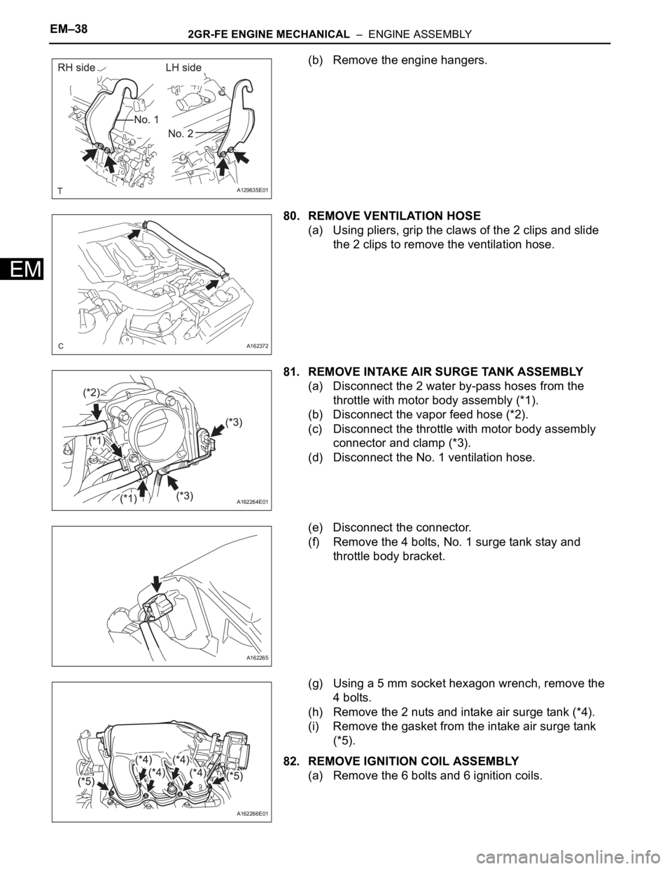
80. REMOVE VENTILATION HOSE
(a) Using pliers, grip the claws of the 2 clips and slide
the 2 clips to remove the ventilation hose.
81. REMOVE INTAKE AIR SURGE TANK ASSEMBLY
(a) Disconnect the 2 water by-pass hoses from the
throttle with motor body assembly (*1).
(b) Disconnect the vapor feed hose (*2).
(c) Disconnect the throttle with motor body assembly
connector and clamp (*3).
(d) Disconnect the No. 1 ventilation hose.
(e) Disconnect the connector.
(f) Remove the 4 bolts, No. 1 surge tank stay and
throttle body bracket.
(g) Using a 5 mm socket hexagon wrench, remove the
4 bolts.
(h) Remove the 2 nuts and intake air surge tank (*4).
(i) Remove the gasket from the intake air surge tank
(*5).
82. REMOVE IGNITION COIL ASSEMBLY
(a) Remove the 6 bolts and 6 ignition coils.
A129635E01
A162372
A162264E01
A162265
A162266E01
Page 45 of 3000
EC–62GR-FE EMISSION CONTROL – EMISSION CONTROL SYSTEM
EC
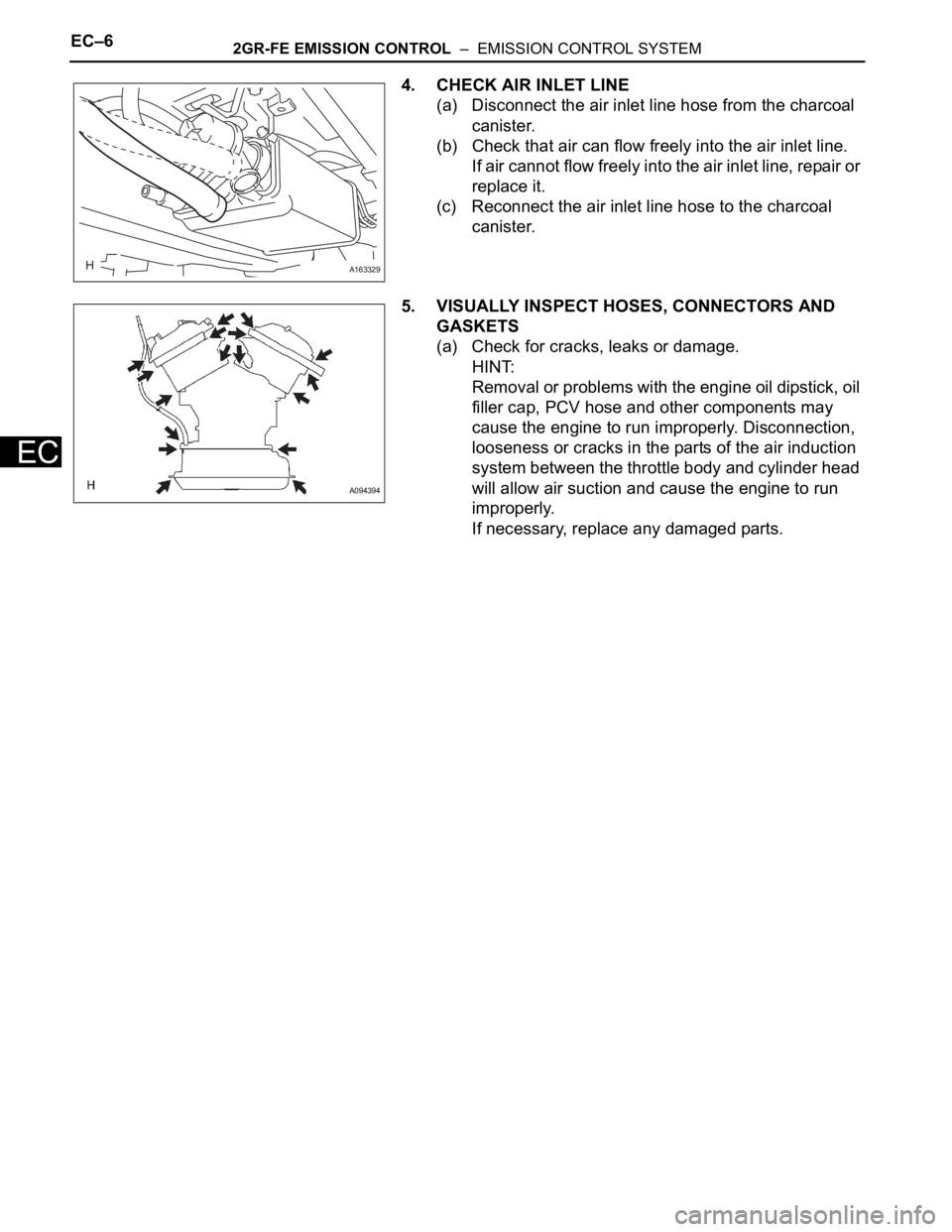
4. CHECK AIR INLET LINE
(a) Disconnect the air inlet line hose from the charcoal
canister.
(b) Check that air can flow freely into the air inlet line.
If air cannot flow freely into the air inlet line, repair or
replace it.
(c) Reconnect the air inlet line hose to the charcoal
canister.
5. VISUALLY INSPECT HOSES, CONNECTORS AND
GASKETS
(a) Check for cracks, leaks or damage.
HINT:
Removal or problems with the engine oil dipstick, oil
filler cap, PCV hose and other components may
cause the engine to run improperly. Disconnection,
looseness or cracks in the parts of the air induction
system between the throttle body and cylinder head
will allow air suction and cause the engine to run
improperly.
If necessary, replace any damaged parts.
A163329
A094394
Page 58 of 3000

INTRODUCTION – TERMSIN–51
IN
IFI Indirect Fuel Injection Indirect Injection (IDL)
IFS Inertia Fuel-Shutoff -
ISC Idle Speed Control -
KS Knock Sensor Knock Sensor
MAF Mass Airflow Air Flow Meter
MAP Manifold Absolute Pressure Manifold Pressure Intake Vacuum
MC Mixture ControlElectric Bleed Air Control Valve (EBCV)
Mixture Control Valve (MCV)
Electric Air Control Valve (EACV)
MDP Manifold Differential Pressure -
MFI Multiport Fuel Injection Electronic Fuel Injection (EFI)
MIL Malfunction Indicator Light Check Engine Light
MST Manifold Surface Temperature -
MVZ Manifold Vacuum Zone -
NVRAM Non-Volatile Random Access Memory -
O2S Oxygen SensorOxygen Sensor, O
2 Sensor (O2S)
OBD On-Board Diagnostic On-Board Diagnostic System (OBD)
OC Oxidation Catalytic Converter Oxidation Catalytic Convert (OC), CCo
OL Open Loop Open Loop
PAIR Pulsed Secondary Air Injection Air Suction (AS)
PCM Powertrain Control Module -
PNP Park/Neutral Position -
PROM Programmable Read Only Memory -
PSP Power Steering Pressure -
PTOX Periodic Trap OxidizerDiesel Particulate Filter (DPF)
Diesel Particulate Trap (DPT)
RAM Random Access Memory Random Access Memory (RAM)
RM Relay Module -
ROM Read Only Memory Read Only Memory (ROM)
RPM Engine Speed Engine Speed
SC Supercharger Supercharger
SCB Supercharger Bypass E-ABV
SFI Sequential Multiport Fuel Injection Electronic Fuel Injection (EFI), Sequential Injection
SPL Smoke Puff Limiter -
SRI Service Reminder Indicator -
SRT System Readiness Test -
ST Scan Tool -
TB Throttle Body Throttle Body
TBI Throttle Body Fuel InjectionSingle Point Injection
Central Fuel Injection (Ci)
TC Turbocharger Turbocharger
TCC Torque Converter Clutch Torque Converter
TCM Transmission Control Module Transmission ECU, ECT ECU
TP Throttle Position Throttle Position
TR Transmission Range -
TVV Thermal Vacuum ValveBimetallic Vacuum Switching Valve (BVSV)
Thermostatic Vacuum Switching Valve (TVSV)
TWC Three-Way Catalytic ConverterThree-Way Catalytic (TWC)
Manifold Converter
CC
RO
SAE
ABBREVIATIONSSAE TERMSTOYOTA TERMS
( )-ABBREVIATIONS
Page 197 of 3000
SS–10SERVICE SPECIFICATIONS – 2GR-FE ENGINE MECHANICAL
SS
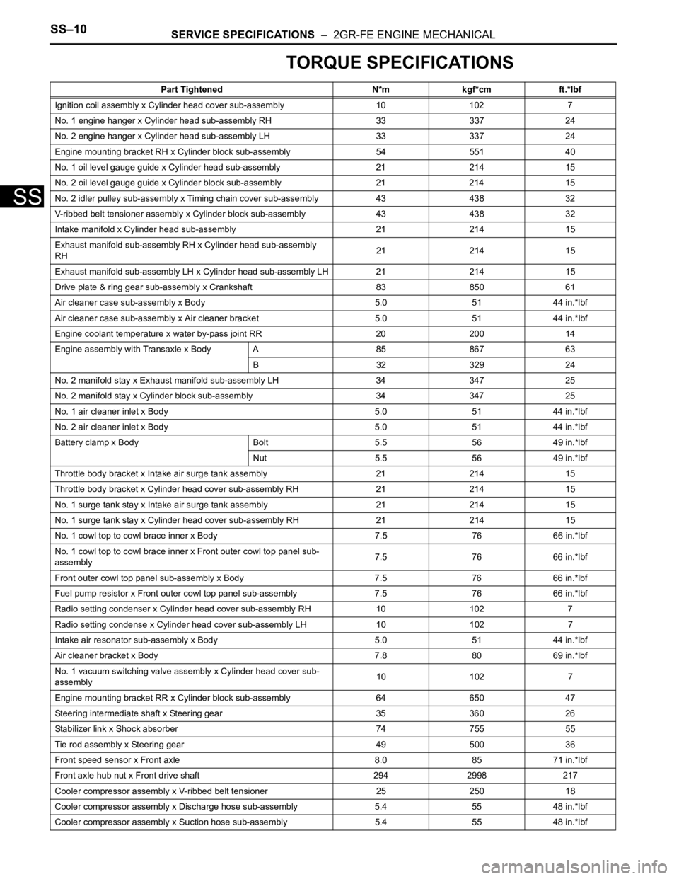
TORQUE SPECIFICATIONS
Part Tightened N*m kgf*cm ft.*lbf
Ignition coil assembly x Cylinder head cover sub-assembly 10 102 7
No. 1 engine hanger x Cylinder head sub-assembly RH 33 337 24
No. 2 engine hanger x Cylinder head sub-assembly LH 33 337 24
Engine mounting bracket RH x Cylinder block sub-assembly 54 551 40
No. 1 oil level gauge guide x Cylinder head sub-assembly 21 214 15
No. 2 oil level gauge guide x Cylinder block sub-assembly 21 214 15
No. 2 idler pulley sub-assembly x Timing chain cover sub-assembly 43 438 32
V-ribbed belt tensioner assembly x Cylinder block sub-assembly 43 438 32
Intake manifold x Cylinder head sub-assembly 21 214 15
Exhaust manifold sub-assembly RH x Cylinder head sub-assembly
RH21 214 15
Exhaust manifold sub-assembly LH x Cylinder head sub-assembly LH 21 214 15
Drive plate & ring gear sub-assembly x Crankshaft 83 850 61
Air cleaner case sub-assembly x Body 5.0 51 44 in.*lbf
Air cleaner case sub-assembly x Air cleaner bracket 5.0 51 44 in.*lbf
Engine coolant temperature x water by-pass joint RR 20 200 14
Engine assembly with Transaxle x Body A 85 867 63
B 32 329 24
No. 2 manifold stay x Exhaust manifold sub-assembly LH 34 347 25
No. 2 manifold stay x Cylinder block sub-assembly 34 347 25
No. 1 air cleaner inlet x Body 5.0 51 44 in.*lbf
No. 2 air cleaner inlet x Body 5.0 51 44 in.*lbf
Battery clamp x Body Bolt 5.5 56 49 in.*lbf
Nut 5.5 56 49 in.*lbf
Throttle body bracket x Intake air surge tank assembly 21 214 15
Throttle body bracket x Cylinder head cover sub-assembly RH 21 21415
No. 1 surge tank stay x Intake air surge tank assembly 21 214 15
No. 1 surge tank stay x Cylinder head cover sub-assembly RH 21 21415
No. 1 cowl top to cowl brace inner x Body 7.5 76 66 in.*lbf
No. 1 cowl top to cowl brace inner x Front outer cowl top panel sub-
assembly7.5 76 66 in.*lbf
Front outer cowl top panel sub-assembly x Body 7.5 76 66 in.*lbf
Fuel pump resistor x Front outer cowl top panel sub-assembly 7.576 66 in.*lbf
Radio setting condenser x Cylinder head cover sub-assembly RH 10102 7
Radio setting condense x Cylinder head cover sub-assembly LH 10 102 7
Intake air resonator sub-assembly x Body 5.0 51 44 in.*lbf
Air cleaner bracket x Body 7.8 80 69 in.*lbf
No. 1 vacuum switching valve assembly x Cylinder head cover sub-
assembly10 102 7
Engine mounting bracket RR x Cylinder block sub-assembly 64 650 47
Steering intermediate shaft x Steering gear 35 360 26
Stabilizer link x Shock absorber 74 755 55
Tie rod assembly x Steering gear 49 500 36
Front speed sensor x Front axle 8.0 85 71 in.*lbf
Front axle hub nut x Front drive shaft 294 2998 217
Cooler compressor assembly x V-ribbed belt tensioner 25 250 18
Cooler compressor assembly x Discharge hose sub-assembly 5.4 55 48 in.*lbf
Cooler compressor assembly x Suction hose sub-assembly 5.4 55 48 in.*lbf
Page 225 of 3000
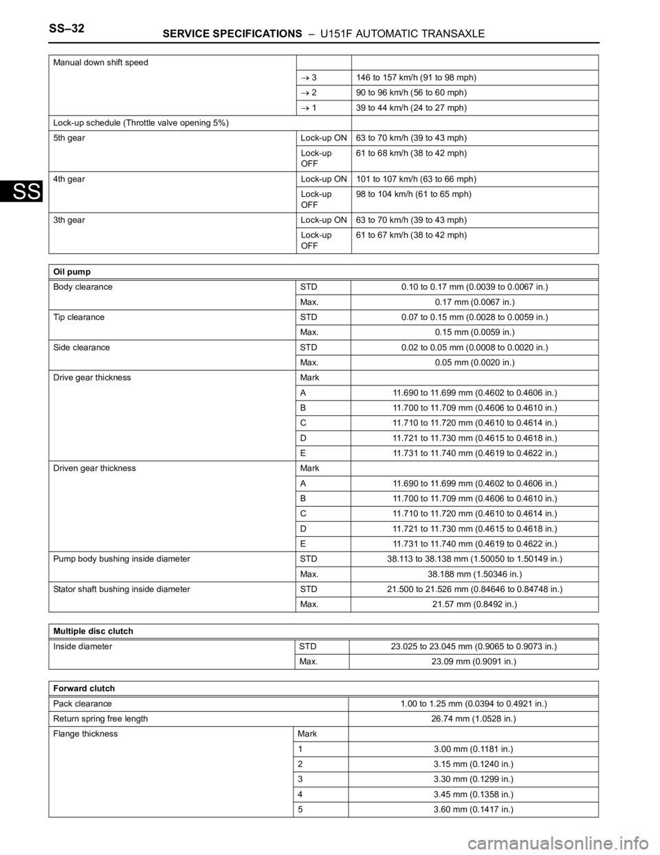
SS–32SERVICE SPECIFICATIONS – U151F AUTOMATIC TRANSAXLE
SS
Manual down shift speed
3 146 to 157 km/h (91 to 98 mph)
2 90 to 96 km/h (56 to 60 mph)
1 39 to 44 km/h (24 to 27 mph)
Lock-up schedule (Throttle valve opening 5%)
5th gear Lock-up ON 63 to 70 km/h (39 to 43 mph)
Lock-up
OFF61 to 68 km/h (38 to 42 mph)
4th gear Lock-up ON 101 to 107 km/h (63 to 66 mph)
Lock-up
OFF98 to 104 km/h (61 to 65 mph)
3th gear Lock-up ON 63 to 70 km/h (39 to 43 mph)
Lock-up
OFF61 to 67 km/h (38 to 42 mph)
Oil pump
Body clearance STD 0.10 to 0.17 mm (0.0039 to 0.0067 in.)
Max. 0.17 mm (0.0067 in.)
Tip clearance STD 0.07 to 0.15 mm (0.0028 to 0.0059 in.)
Max. 0.15 mm (0.0059 in.)
Side clearance STD 0.02 to 0.05 mm (0.0008 to 0.0020 in.)
Max. 0.05 mm (0.0020 in.)
Drive gear thickness Mark
A 11.690 to 11.699 mm (0.4602 to 0.4606 in.)
B 11.700 to 11.709 mm (0.4606 to 0.4610 in.)
C 11.710 to 11.720 mm (0.4610 to 0.4614 in.)
D 11.721 to 11.730 mm (0.4615 to 0.4618 in.)
E 11.731 to 11.740 mm (0.4619 to 0.4622 in.)
Driven gear thickness Mark
A 11.690 to 11.699 mm (0.4602 to 0.4606 in.)
B 11.700 to 11.709 mm (0.4606 to 0.4610 in.)
C 11.710 to 11.720 mm (0.4610 to 0.4614 in.)
D 11.721 to 11.730 mm (0.4615 to 0.4618 in.)
E 11.731 to 11.740 mm (0.4619 to 0.4622 in.)
Pump body bushing inside diameter STD 38.113 to 38.138 mm (1.50050 to 1.50149 in.)
Max. 38.188 mm (1.50346 in.)
Stator shaft bushing inside diameter STD 21.500 to 21.526 mm (0.84646 to 0.84748 in.)
Max. 21.57 mm (0.8492 in.)
Multiple disc clutch
Inside diameter STD 23.025 to 23.045 mm (0.9065 to 0.9073 in.)
Max. 23.09 mm (0.9091 in.)
Forward clutch
Pack clearance1.00 to 1.25 mm (0.0394 to 0.4921 in.)
Return spring free length26.74 mm (1.0528 in.)
Flange thickness Mark
1 3.00 mm (0.1181 in.)
2 3.15 mm (0.1240 in.)
3 3.30 mm (0.1299 in.)
4 3.45 mm (0.1358 in.)
5 3.60 mm (0.1417 in.)