2007 TOYOTA SIENNA automatic transmission fluid
[x] Cancel search: automatic transmission fluidPage 1390 of 3000

U151E AUTOMATIC TRANSAXLE – AUTOMATIC TRANSAXLE SYSTEMAX–13
AX
MECHANICAL SYSTEM TESTS
1. PERFORM MECHANICAL SYSTEM TESTS
(a) Measure the stall speed.
The object of this test is to check the overall
performance of the transaxle and engine by
measuring the stall speeds in the D position.
NOTICE:
• Driving test should be done on a paved road
(a nonskid road).
• Perform the test at the normal operating ATF
(Automatic Transmission Fluid) temperature
50 to 80
C (122 to 176F).
• Do not continuously run this test for longer
than 10 seconds.
• To ensure safety, do this test in a wide, clear
level area which provides good traction.
• The stall test should always be carried out in
pairs. One technician should observe the
conditions of wheels or wheel stoppers
outside the vehicle while the other is doing
the test.
(1) Chock the 4 wheels.
(2) Connect the intelligent tester together with the
CAN VIM (controller area network vehicle
interface module) to the DLC3.
(3) Fully apply the parking brake.
(4) Keep your left foot pressed firmly on the brake
pedal.
(5) Start the engine.
(6) Shift into the D position. Press all the way down
on the accelerator pedal with your right foot.
(7) Quickly read the stall speed at this time.
Stall speed:
2,300 +- 150 rpm
Evaluation:
Problem Possible cause
(a) Stall engine speed is low in D position• Engine power output may be insufficient
• Stator one-way clutch not operating properly
HINT:
If the value is less than the specified value by 600 rpm or more, the
torque converter could be faulty.
(b) Stall engine speed is high in D position• Line pressure is too low
• Forward clutch slipping
• U/D (Underdrive) brake slipping
• U/D (Underdrive) one-way clutch is not operating properly
• No.1 one-way clutch not operating properly
• Improper fluid level
Page 1391 of 3000

AX–14U151E AUTOMATIC TRANSAXLE – AUTOMATIC TRANSAXLE SYSTEM
AX
(b) Measure the time lag.
(1) When the shift lever is shifted while the engine is
idling, there will be a certain time lapse or lag
before the shock can be felt. This is used for
checking the condition of the clutch and brake.
NOTICE:
• Perform the test at the normal operating
ATF (Automatic Transmission Fluid)
temperature: 50 to 80
C (122 to 176F).
• Be sure to allow 1 minute interval between
tests.
• Perform the test three times, and measure
the time lags. Calculate the average value
of the three time lags.
• When conducting stall test, do not
continue more than 10 seconds.
(2) Connect the intelligent tester together with the
CAN VIM (controller area network vehicle
interface module) to the DLC3.
(3) Fully apply the parking brake.
(4) Start and warm up the engine and check idle
speed.
Idle speed:
approx. 700 rpm (In N position and A/C
OFF)
(5) Shift the lever from N to D position. Using a stop
watch, measure the time from when the lever is
shifted until the shock is felt.
Time lag:
N
D less than 1.2 seconds
(6) In the same way, measure the time lag for N
R.
Time lag:
N
R less than 1.5 seconds
Evaluation (If N
D or N R time lag is longer than the specified):
Problem Possible cause
N
D time lag is longer• Line pressure is too low
• Forward clutch worn
• No.1 one-way clutch is not operating properly
• U/D (Underdrive) one-way clutch is not operating
• U/D (Underdrive) brake worn
N
R time lag is longer• Line pressure is too low
• Reverse clutch worn
• 1st and reverse brake worn
• U/D (Underdrive) brake worn
Page 1392 of 3000

U151E AUTOMATIC TRANSAXLE – AUTOMATIC TRANSAXLE SYSTEMAX–15
AX
HYDRAULIC TEST
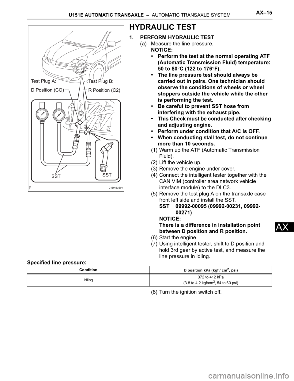
1. PERFORM HYDRAULIC TEST
(a) Measure the line pressure.
NOTICE:
• Perform the test at the normal operating ATF
(Automatic Transmission Fluid) temperature:
50 to 80
C (122 to 176F).
• The line pressure test should always be
carried out in pairs. One technician should
observe the conditions of wheels or wheel
stoppers outside the vehicle while the other
is performing the test.
• Be careful to prevent SST hose from
interfering with the exhaust pipe.
• This Check must be conducted after checking
and adjusting engine.
• Perform under condition that A/C is OFF.
• When conducting stall test, do not continue
more than 10 seconds.
(1) Warm up the ATF (Automatic Transmission
Fluid).
(2) Lift the vehicle up.
(3) Remove the engine under cover.
(4) Connect the intelligent tester together with the
CAN VIM (controller area network vehicle
interface module) to the DLC3.
(5) Remove the test plug A on the transaxle case
front left side and install the SST.
SST 09992-00095 (09992-00231, 09992-
00271)
NOTICE:
There is a difference in installation point
between D position and R position.
(6) Start the engine.
(7) Using intelligent tester, shift to D position and
hold 3rd gear by active test, and measure the
line pressure in idling.
Specified line pressure:
(8) Turn the ignition switch off.
C160153E01
Condition
D position kPa (kgf / cm2, psi)
Idling372 to 412 kPa
(3.8 to 4.2 kgf/cm
2, 54 to 60 psi)
Page 1393 of 3000

AX–16U151E AUTOMATIC TRANSAXLE – AUTOMATIC TRANSAXLE SYSTEM
AX
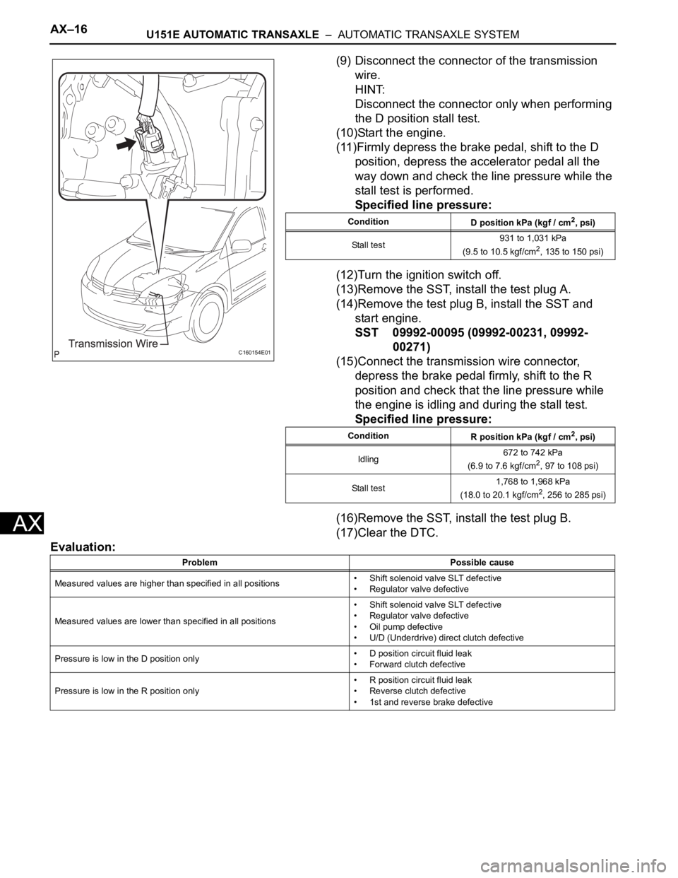
(9) Disconnect the connector of the transmission
wire.
HINT:
Disconnect the connector only when performing
the D position stall test.
(10)Start the engine.
(11)Firmly depress the brake pedal, shift to the D
position, depress the accelerator pedal all the
way down and check the line pressure while the
stall test is performed.
Specified line pressure:
(12)Turn the ignition switch off.
(13)Remove the SST, install the test plug A.
(14)Remove the test plug B, install the SST and
start engine.
SST 09992-00095 (09992-00231, 09992-
00271)
(15)Connect the transmission wire connector,
depress the brake pedal firmly, shift to the R
position and check that the line pressure while
the engine is idling and during the stall test.
Specified line pressure:
(16)Remove the SST, install the test plug B.
(17)Clear the DTC.
Evaluation:
C160154E01
Condition
D position kPa (kgf / cm2, psi)
Stall test931 to 1,031 kPa
(9.5 to 10.5 kgf/cm
2, 135 to 150 psi)
Condition
R position kPa (kgf / cm
2, psi)
Idling672 to 742 kPa
(6.9 to 7.6 kgf/cm
2, 97 to 108 psi)
Stall test1,768 to 1,968 kPa
(18.0 to 20.1 kgf/cm
2, 256 to 285 psi)
Problem Possible cause
Measured values are higher than specified in all positions• Shift solenoid valve SLT defective
• Regulator valve defective
Measured values are lower than specified in all positions• Shift solenoid valve SLT defective
• Regulator valve defective
• Oil pump defective
• U/D (Underdrive) direct clutch defective
Pressure is low in the D position only• D position circuit fluid leak
• Forward clutch defective
Pressure is low in the R position only• R position circuit fluid leak
• Reverse clutch defective
• 1st and reverse brake defective
Page 1406 of 3000

AX–36U151E AUTOMATIC TRANSAXLE – AUTOMATIC TRANSAXLE SYSTEM
AX
FAIL-SAFE CHART
1. FAIL-SAFE
This function minimizes the loss of the ECT functions
when any malfunction occurs in a sensor or solenoid.
(a) ATF (Automatic Transmission Fluid) temperature
sensor:
When the ATF temperature sensor has a
malfunction, 5th upshift is prohibited.
(b) Counter gear speed sensor NC (Speed sensor NC):
When the counter gear speed sensor has a
malfunction, 5th upshift is prohibited.
(c) Shift solenoid valve DSL:
When the solenoid valve DSL has a malfunction, the
current to the solenoid valve is stopped.
This stops lock-up control, then fuel economy
decreases.
(d) Shift solenoid valve SL1, SL2, SL3 and S4:
Fail safe function:
If either of the shift solenoid valve circuits develops
an open or short, the ECM turns the other shift
solenoid "ON" and "OFF" in order to shift into the
gear positions shown in the table below.
Manual shifting as shown in the following table must
be done (In case of a short circuit, the ECM stops
sending the current to the short circuited solenoid).
Even if starting the engine in the fail-safe mode, the
gear position remains in the same position.
HINT:
FL: Flex Lock-up
NormalSolenoid ValveSL1 ON OFF ON OFF OFF
SL2 ON ON OFF FL FL
SL3 OFF OFF OFF ON ON
S4 OFF OFF OFF OFF ON
Gear Position 1st 2nd 3rd 4th 5th
SL1
Malfunction
(During driving
at 1st or 2nd)Solenoid ValveSL1 OFF
SL2 ON ON OFF to ON FL to ON FL to ON
SL3 OFF OFF OFF ON to OFF ON to OFF
S4 OFF OFF OFF OFF ON to OFF
Gear Position 1st to 2nd 2nd 3rd to 2nd 4th to 2nd 5th to 2nd
SL1
Malfunction
(During driving
at 3rd)Solenoid ValveSL1 OFF
SL2 ON to FL ON to FL OFF to FL FL FL
SL3 OFF OFF OFF ON to OFF ON to OFF
S4 OFF to ON OFF to ON OFF to ON OFF to ON ON
Gear Position 1st to 4th 2nd to 4th 3rd to 4th 4th 5th to 4th
SL1
Malfunction
(During driving
at 4th or 5th)Solenoid ValveSL1 OFF
SL2 ON to FL ON to FL OFF to FL FL FL
SL3 OFF to ON OFF to ON OFF to ON ON ON
S4 OFF OFF OFF OFF ON
Gear Position 1st to 4th 2nd to 4th 3rd to 4th 4th 5th to 4th
Page 1408 of 3000

AX–42U151E AUTOMATIC TRANSAXLE – AUTOMATIC TRANSAXLE SYSTEM
AX
DIAGNOSTIC TROUBLE CODE CHART
If a DTC is displayed during the DTC check, check the parts
listed in the table below and proceed to the page given.
HINT:
• *1: Comes on MIL (Malfunction Indicator Lamp) light up
• *2: "DTC stored" mark means ECM memorizes the
malfunction code if the ECM detects the DTC detection
condition.
• This DTC may be output when the clutch, brake and gear
components etc. inside the automatic transmission are
damaged.
AUTOMATIC TRANSAXLE SYSTEM:
DTC Code Detection Item Trouble Area MIL *1 Memory *2 See page
P0705Transmission Range Sensor Circuit
Malfunction (PRNDL Input)1. Open or short in park/neutral position
switch circuit
2. Park/neutral position switch
3. ECMComes on DTC storedAX-38
P0710Transmission Fluid Temperature Sensor
"A" Circuit1. Open or short in ATF temperature
sensor circuit
2. Transmission wire (ATF temperature
sensor)
3. ECMComes on DTC storedAX-43
P0711Transmission Fluid Temperature Sensor
"A" PerformanceTransmission wire (ATF temperature
sensor)Comes on DTC storedAX-48
P0712Transmission Fluid Temperature Sensor
"A" Circuit Low Input1. Short in ATF temperature sensor
circuit
2. Transmission wire (ATF temperature
sensor)
3. ECMComes on DTC storedAX-43
P0713Transmission Fluid Temperature Sensor
"A" Circuit High Input1. Open in ATF temperature sensor
circuit
2. Transmission wire (ATF temperature
sensor)
3. ECMComes on DTC storedAX-43
P0717 Turbine Speed Sensor Circuit No Signal1. Open or short in transmission
revolution sensor NT (speed sensor NT)
circuit
2. Transmission revolution sensor NT
(speed sensor NT)
3. ECM
4. Automatic transaxle assemblyComes on DTC storedAX-52
P0724 Brake Switch "B" Circuit High1. Short in stop light switch circuit
2. Stop light switch
3. ECMComes on DTC storedAX-56
P0741Torque Converter Clutch Solenoid
Performance (Shift Solenoid Valve DSL)1. Shift solenoid valve DSL remains
open or closed
2. Valve body is blocked
3. Torque converter clutch
4. Automatic transaxle (clutch, brake or
gear etc.)
5. Line pressure is too lowComes on DTC storedAX-60
P0746Pressure Control Solenoid "A"
Performance (Shift Solenoid Valve SL1)1. Shift solenoid valve SL1 remains open
or closed
2. Valve body is blocked
3. Automatic transaxle (clutch, brake or
gear etc.)Comes on DTC storedAX-66
P0748Pressure Control Solenoid "A" Electrical
(Shift Solenoid Valve SL1)1. Open or short in shift solenoid valve
SL1 circuit
2. Shift solenoid valve SL1
3. ECMComes on DTC storedAX-70
Page 1416 of 3000

AX–50U151E AUTOMATIC TRANSAXLE – AUTOMATIC TRANSAXLE SYSTEM
AX
DESCRIPTION
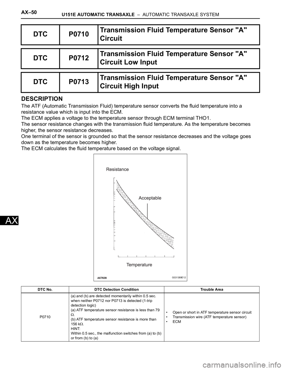
The ATF (Automatic Transmission Fluid) temperature sensor converts the fluid temperature into a
resistance value which is input into the ECM.
The ECM applies a voltage to the temperature sensor through ECM terminal THO1.
The sensor resistance changes with the transmission fluid temperature. As the temperature becomes
higher, the sensor resistance decreases.
One terminal of the sensor is grounded so that the sensor resistance decreases and the voltage goes
down as the temperature becomes higher.
The ECM calculates the fluid temperature based on the voltage signal.
DTC P0710Transmission Fluid Temperature Sensor "A"
Circuit
DTC P0712Transmission Fluid Temperature Sensor "A"
Circuit Low Input
DTC P0713Transmission Fluid Temperature Sensor "A"
Circuit High Input
DTC No. DTC Detection Condition Trouble Area
P0710(a) and (b) are detected momentarily within 0.5 sec.
when neither P0712 nor P0713 is detected (1-trip
detection logic)
(a) ATF temperature sensor resistance is less than 79
.
(b) ATF temperature sensor resistance is more than
156 k
.
HINT:
Within 0.5 sec., the malfunction switches from (a) to (b)
or from (b) to (a)• Open or short in ATF temperature sensor circuit
• Transmission wire (ATF temperature sensor)
•ECM
G031389E12
Page 1417 of 3000

U151E AUTOMATIC TRANSAXLE – AUTOMATIC TRANSAXLE SYSTEMAX–51
AX
MONITOR DESCRIPTION
These DTCs indicate an open or short in the automatic transmission fluid (ATF) temperature sensor (TFT
sensor) circuit. The automatic transmission fluid (ATF) temperature sensor converts ATF temperature to
an electrical resistance value. Based on the resistance, the ECM determines the ATF temperature, and
the ECM detects an opens or shorts in the ATF temperature circuit. If the resistance value of the ATF
temperature is less than 79
*1or more than 156 k *2, the ECM interprets this as a fault in the ATF
sensor or wiring. The ECM will turn on the MIL and store the DTC.
*1: 150
C (302F) or more is indicated regardless of the actual ATF temperature.
*2: -40
C (-40F) is indicated regardless of the actual ATF temperature.
HINT:
The ATF temperature can be checked on the OBD II scan tool or intelligent tester display.
MONITOR STRATEGY
TYPICAL ENABLING CONDITIONS
P0710: Range check (Chattering)
P0712: Range check (Low resistance)
P0713: Range check (High resistance)
TYPICAL MALFUNCTION THRESHOLDS
P0710: Range check (Chattering)
P0712: Range check (Low resistance)
P0713: Range check (High resistance)
P0712ATF temperature sensor resistance is less than 79
for 0.5 sec. or more (1-trip detection logic)• Short in ATF temperature sensor circuit
• Transmission wire (ATF temperature sensor)
•ECM
P0713ATF temperature sensor resistance is more than 156
k
when 15 minutes or more have elapsed after the
engine start
DTC is detected for 0.5 sec. or more (1-trip detection
logic)• Open in ATF temperature sensor circuit
• Transmission wire (ATF temperature sensor)
•ECM
Related DTCsP0710: ATF temperature sensor/Range check (Chattering)
P0712: ATF temperature sensor/Range check (Low resistance)
P0713: ATF temperature sensor/Range check (High resistance)
Required sensors/Components ATF temperature sensor (TFT sensor)
Frequency of operation Continuous
Duration 0.5 sec.
MIL operation Immediate
Sequence of operation None
The monitor will run whenever these DTCs are not present. None
The typical enabling condition is not available. -
The monitor will run whenever this DTC is not present. None
Time after engine start 15 min. or more
TFT (Transmission fluid temperature) sensor resistanceLess than 79
or
More than 156 k
TFT sensor resistanceLess than 79
TFT sensor resistance More than 156 k
DTC No. DTC Detection Condition Trouble Area