Page 686 of 3000

2GR-FE ENGINE CONTROL SYSTEM – SFI SYSTEMES–393
ES
MONITOR DESCRIPTION
5 hours after the ignition switch is turned off, the soak timer activates the ECM to begin the EVAP system
monitor. While the engine is running, the ECM monitors the synchronization of the soak timer and the
CPU clock. If these two are not synchronized, the ECM interprets this as a malfunction, illuminates the
MIL and sets the DTC (2 trip detection logic).
MONITOR STRATEGY
TYPICAL ENABLING CONDITIONS
TYPICAL MALFUNCTION THRESHOLDS
INSPECTION PROCEDURE
HINT:
• DTC P2610 is set if an internal ECM problem is detected. Diagnostic procedures are not required.
ECM replacement is required.
• Read freeze frame data using the intelligent tester. The ECM records vehicle and driving condition
information as freeze frame data the moment a DTC is stored. When troubleshooting, freeze frame
data can be helpful in determining whether the vehicle was running or stopped, whether the engine
was warmed up or not, whether the air-fuel ratio was lean or rich, as well as other data recorded at the
time of a malfunction.
(a) Replace the ECM (See page ES-498).
NEXT
(a) Connect the intelligent tester to the DLC3.
(b) Turn the ignition switch to the ON position.
(c) Clear the DTCs (See page ES-39).
(d) Start the engine and wait for 10 minutes or more.
Required Sensors / Components ECM
Frequency of Operation Once per driving cycle
Duration 10 minutes
MIL Operation 2 driving cycles
Sequence of Operation None
The monitor will run whenever these DTCs are not
presentNone
Ignition switch ON
Engine Running
Battery voltage 8 V or more
Sta r t e r OF F
Soak timer measurement when ECM CPU clock counts
10 minutesLess than 7 minutes or more than 13 minutes
1REPLACE ECM
2CHECK WHETHER DTC OUTPUT RECURS
Page 1341 of 3000

CH–62GR-FE CHARGING – CHARGING SYSTEM
CH
ON-VEHICLE INSPECTION
1. CHECK BATTERY ELECTROLYTE LEVEL
(a) Check the electrolyte level.
(1) If the electrolyte level is low, replace the battery
(or add distilled water) and check the charging
system.
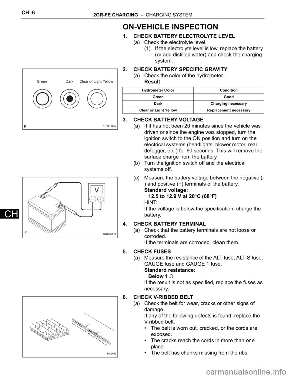
2. CHECK BATTERY SPECIFIC GRAVITY
(a) Check the color of the hydrometer.
Result
3. CHECK BATTERY VOLTAGE
(a) If it has not been 20 minutes since the vehicle was
driven or since the engine was stopped, turn the
ignition switch to the ON position and turn on the
electrical systems (headlights, blower motor, rear
defogger, etc.) for 60 seconds. This will remove the
surface charge from the battery.
(b) Turn the ignition switch off and the electrical
systems off.
(c) Measure the battery voltage between the negative (-
) and positive (+) terminals of the battery.
Standard voltage:
12.5 to 12.9 V at 20
C (68F)
HINT:
If the voltage is below the specification, charge the
battery.
4. CHECK BATTERY TERMINAL
(a) Check that the battery terminals are not loose or
corroded.
If the terminals are corroded, clean them.
5. CHECK FUSES
(a) Measure the resistance of the ALT fuse, ALT-S fuse,
GAUGE fuse and GAUGE 1 fuse.
Standard resistance:
Below 1
If the result is not as specified, replace the fuses as
necessary.
6. CHECK V-RIBBED BELT
(a) Check the belt for wear, cracks or other signs of
damage.
If any of the following defects is found, replace the
V-ribbed belt.
• The belt is worn out, cracked, or the cords are
exposed.
• The cracks reach the cords in more than one
place.
• The belt has chunks missing from the ribs.
A115815E02
Hydrometer Color Condition
Green Good
Dark Charging necessary
Clear or Light Yellow Replacement necessary
A081052E01
B000543
Page 1346 of 3000

CH–62GR-FE CHARGING – CHARGING SYSTEM
CH
ON-VEHICLE INSPECTION
1. CHECK BATTERY ELECTROLYTE LEVEL
(a) Check the electrolyte level.
(1) If the electrolyte level is low, replace the battery
(or add distilled water) and check the charging
system.
2. CHECK BATTERY SPECIFIC GRAVITY
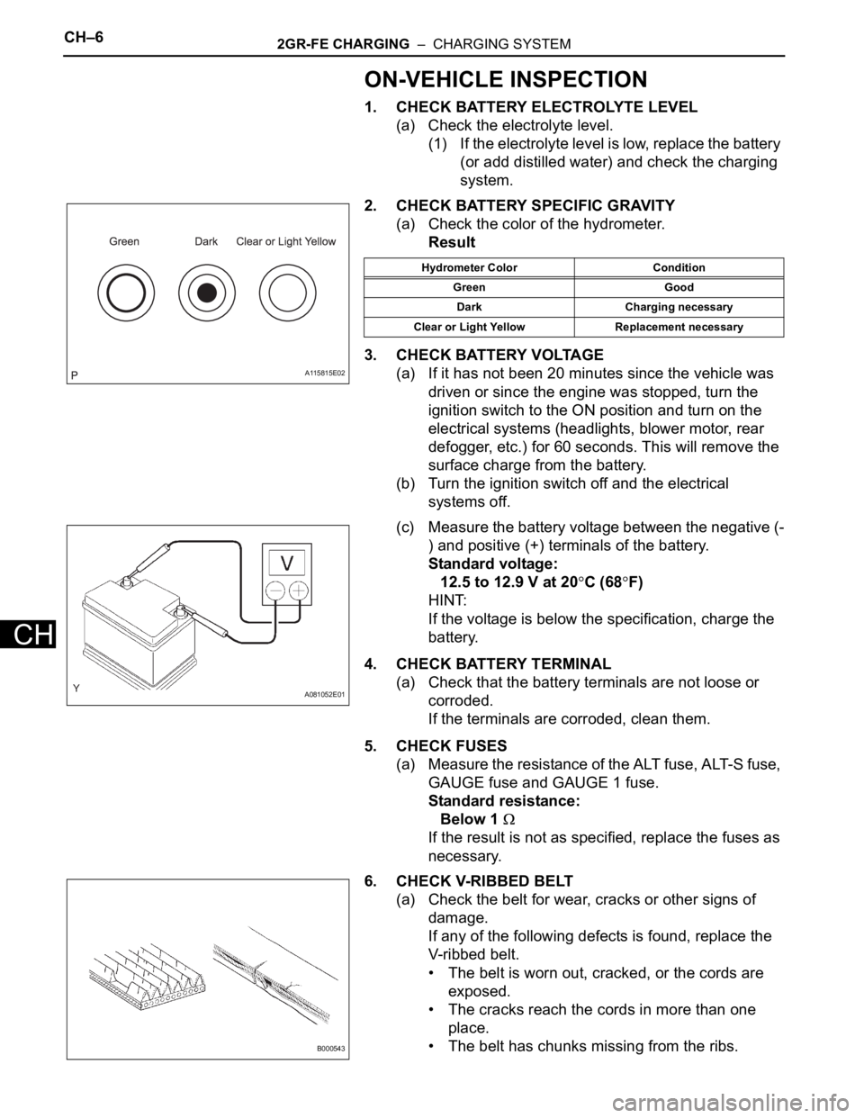
(a) Check the color of the hydrometer.
Result
3. CHECK BATTERY VOLTAGE
(a) If it has not been 20 minutes since the vehicle was
driven or since the engine was stopped, turn the
ignition switch to the ON position and turn on the
electrical systems (headlights, blower motor, rear
defogger, etc.) for 60 seconds. This will remove the
surface charge from the battery.
(b) Turn the ignition switch off and the electrical
systems off.
(c) Measure the battery voltage between the negative (-
) and positive (+) terminals of the battery.
Standard voltage:
12.5 to 12.9 V at 20
C (68F)
HINT:
If the voltage is below the specification, charge the
battery.
4. CHECK BATTERY TERMINAL
(a) Check that the battery terminals are not loose or
corroded.
If the terminals are corroded, clean them.
5. CHECK FUSES
(a) Measure the resistance of the ALT fuse, ALT-S fuse,
GAUGE fuse and GAUGE 1 fuse.
Standard resistance:
Below 1
If the result is not as specified, replace the fuses as
necessary.
6. CHECK V-RIBBED BELT
(a) Check the belt for wear, cracks or other signs of
damage.
If any of the following defects is found, replace the
V-ribbed belt.
• The belt is worn out, cracked, or the cords are
exposed.
• The cracks reach the cords in more than one
place.
• The belt has chunks missing from the ribs.
A115815E02
Hydrometer Color Condition
Green Good
Dark Charging necessary
Clear or Light Yellow Replacement necessary
A081052E01
B000543