2007 TOYOTA SIENNA relay
[x] Cancel search: relayPage 54 of 3000
IN–42INTRODUCTION – HOW TO TROUBLESHOOT ECU CONTROLLED SYSTEMS
IN
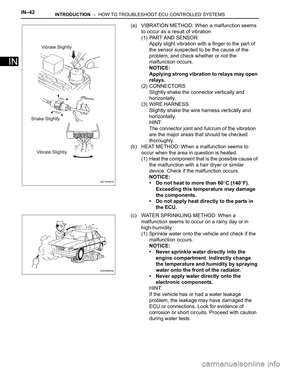
(a) VIBRATION METHOD: When a malfunction seems
to occur as a result of vibration.
(1) PART AND SENSOR
Apply slight vibration with a finger to the part of
the sensor suspected to be the cause of the
problem, and check whether or not the
malfunction occurs.
NOTICE:
Applying strong vibration to relays may open
relays.
(2) CONNECTORS
Slightly shake the connector vertically and
horizontally.
(3) WIRE HARNESS
Slightly shake the wire harness vertically and
horizontally.
HINT:
The connector joint and fulcrum of the vibration
are the major areas that should be checked
thoroughly.
(b) HEAT METHOD: When a malfunction seems to
occur when the area in question is heated.
(1) Heat the component that is the possible cause of
the malfunction with a hair dryer or similar
device. Check if the malfunction occurs.
NOTICE:
• Do not heat to more than 60
C (140F).
Exceeding this temperature may damage
the components.
• Do not apply heat directly to the parts in
the ECU.
(c) WATER SPRINKLING METHOD: When a
malfunction seems to occur on a rainy day or in
high-humidity.
(1) Sprinkle water onto the vehicle and check if the
malfunction occurs.
NOTICE:
• Never sprinkle water directly into the
engine compartment. Indirectly change
the temperature and humidity by spraying
water onto the front of the radiator.
• Never apply water directly onto the
electronic components.
HINT:
If the vehicle has or had a water leakage
problem, the leakage may have damaged the
ECU or connections. Look for evidence of
corrosion or short circuits. Proceed with caution
during water tests.B071602E03
D025085E02
Page 58 of 3000

INTRODUCTION – TERMSIN–51
IN
IFI Indirect Fuel Injection Indirect Injection (IDL)
IFS Inertia Fuel-Shutoff -
ISC Idle Speed Control -
KS Knock Sensor Knock Sensor
MAF Mass Airflow Air Flow Meter
MAP Manifold Absolute Pressure Manifold Pressure Intake Vacuum
MC Mixture ControlElectric Bleed Air Control Valve (EBCV)
Mixture Control Valve (MCV)
Electric Air Control Valve (EACV)
MDP Manifold Differential Pressure -
MFI Multiport Fuel Injection Electronic Fuel Injection (EFI)
MIL Malfunction Indicator Light Check Engine Light
MST Manifold Surface Temperature -
MVZ Manifold Vacuum Zone -
NVRAM Non-Volatile Random Access Memory -
O2S Oxygen SensorOxygen Sensor, O
2 Sensor (O2S)
OBD On-Board Diagnostic On-Board Diagnostic System (OBD)
OC Oxidation Catalytic Converter Oxidation Catalytic Convert (OC), CCo
OL Open Loop Open Loop
PAIR Pulsed Secondary Air Injection Air Suction (AS)
PCM Powertrain Control Module -
PNP Park/Neutral Position -
PROM Programmable Read Only Memory -
PSP Power Steering Pressure -
PTOX Periodic Trap OxidizerDiesel Particulate Filter (DPF)
Diesel Particulate Trap (DPT)
RAM Random Access Memory Random Access Memory (RAM)
RM Relay Module -
ROM Read Only Memory Read Only Memory (ROM)
RPM Engine Speed Engine Speed
SC Supercharger Supercharger
SCB Supercharger Bypass E-ABV
SFI Sequential Multiport Fuel Injection Electronic Fuel Injection (EFI), Sequential Injection
SPL Smoke Puff Limiter -
SRI Service Reminder Indicator -
SRT System Readiness Test -
ST Scan Tool -
TB Throttle Body Throttle Body
TBI Throttle Body Fuel InjectionSingle Point Injection
Central Fuel Injection (Ci)
TC Turbocharger Turbocharger
TCC Torque Converter Clutch Torque Converter
TCM Transmission Control Module Transmission ECU, ECT ECU
TP Throttle Position Throttle Position
TR Transmission Range -
TVV Thermal Vacuum ValveBimetallic Vacuum Switching Valve (BVSV)
Thermostatic Vacuum Switching Valve (TVSV)
TWC Three-Way Catalytic ConverterThree-Way Catalytic (TWC)
Manifold Converter
CC
RO
SAE
ABBREVIATIONSSAE TERMSTOYOTA TERMS
( )-ABBREVIATIONS
Page 72 of 3000
IN–42INTRODUCTION – HOW TO TROUBLESHOOT ECU CONTROLLED SYSTEMS
IN
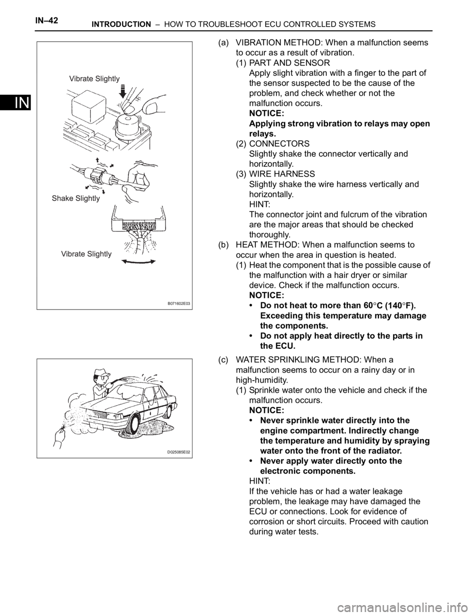
(a) VIBRATION METHOD: When a malfunction seems
to occur as a result of vibration.
(1) PART AND SENSOR
Apply slight vibration with a finger to the part of
the sensor suspected to be the cause of the
problem, and check whether or not the
malfunction occurs.
NOTICE:
Applying strong vibration to relays may open
relays.
(2) CONNECTORS
Slightly shake the connector vertically and
horizontally.
(3) WIRE HARNESS
Slightly shake the wire harness vertically and
horizontally.
HINT:
The connector joint and fulcrum of the vibration
are the major areas that should be checked
thoroughly.
(b) HEAT METHOD: When a malfunction seems to
occur when the area in question is heated.
(1) Heat the component that is the possible cause of
the malfunction with a hair dryer or similar
device. Check if the malfunction occurs.
NOTICE:
• Do not heat to more than 60
C (140F).
Exceeding this temperature may damage
the components.
• Do not apply heat directly to the parts in
the ECU.
(c) WATER SPRINKLING METHOD: When a
malfunction seems to occur on a rainy day or in
high-humidity.
(1) Sprinkle water onto the vehicle and check if the
malfunction occurs.
NOTICE:
• Never sprinkle water directly into the
engine compartment. Indirectly change
the temperature and humidity by spraying
water onto the front of the radiator.
• Never apply water directly onto the
electronic components.
HINT:
If the vehicle has or had a water leakage
problem, the leakage may have damaged the
ECU or connections. Look for evidence of
corrosion or short circuits. Proceed with caution
during water tests.B071602E03
D025085E02
Page 236 of 3000

THEFT DETERRENT – THEFT DETERRENT SYSTEMTD–3
TD
SYSTEM DESCRIPTION
1. OUTLINE OF THEFT DETERRENT SYSTEM
(a) When the theft deterrent system detects that the
vehicle is being tampered with, the system sets off
the alarm, causing the horns to sound and the lights
to light up or blink in order to alert people around the
vehicle to the theft.
(b) The theft deterrent system has 2 modes; one is the
active arming mode (see ACTIVE ARMING MODE)
and the other is passive arming mode (see
PASSIVE ARMING MODE). The passive arming
mode can be switched ON/OFF using the specified
method.
(c) Each mode has 4 states; a disarmed state, an
arming preparation state, an armed state and an
alarm sounding state.
(1) Disarmed state:
• The alarm function is not operating.
• The theft deterrent system is not operating.
(2) Arming preparation state:
• The time until the system goes into the armed
state.
• The theft deterrent system is not operating.
(3) Armed state:
• The theft deterrent system is operating.
(4) Alarm sounding state:
• Alarm function is operating.
Alarm time:
Approx. 60 sec.
Refer to table below for alarm method and time:
HINT:
If any of the doors are unlocked with no key in
the ignition key cylinder during the armed state,
a forced door lock signal will be output (see
FORCED DOOR LOCK CONTROL).
2. ACTIVE ARMING MODE
HINT:
• Active arming mode starts the alarm control
immediately after the doors are locked.
• This system activates as described in the diagram
below when one of items for each condition is met.
Alarm MethodHeadlight Blinking (approx. 0.4 second cycles)
Taillight Blinking (approx. 0.4 second cycles)
Hazard Warning Light Blinking (cycles of flasher relay)
Interior Light Illuminating
Vehicle HornSounding
(approx. 0.4 second cycles)
Security HornSounding
(approx. 0.4 second cycles)
Alarm Time Approx. 60 sec.
Page 283 of 3000
WS–66WINDSHIELD / WINDOWGLASS – WINDOW DEFOGGER SYSTEM
WS
PROBLEM SYMPTOMS TABLE
WINDOW DEFOGGER SYSTEM
ON-VEHICLE INSPECTION
1. INSPECT BACK WINDOW (DEFOGGER WIRE)
NOTICE:
• When cleaning the glass, wipe the glass along the
wire using a soft and dry cloth. Take care not to
damage the wires.
• Do not use detergents or glass cleaners including
abrasive ingredients.
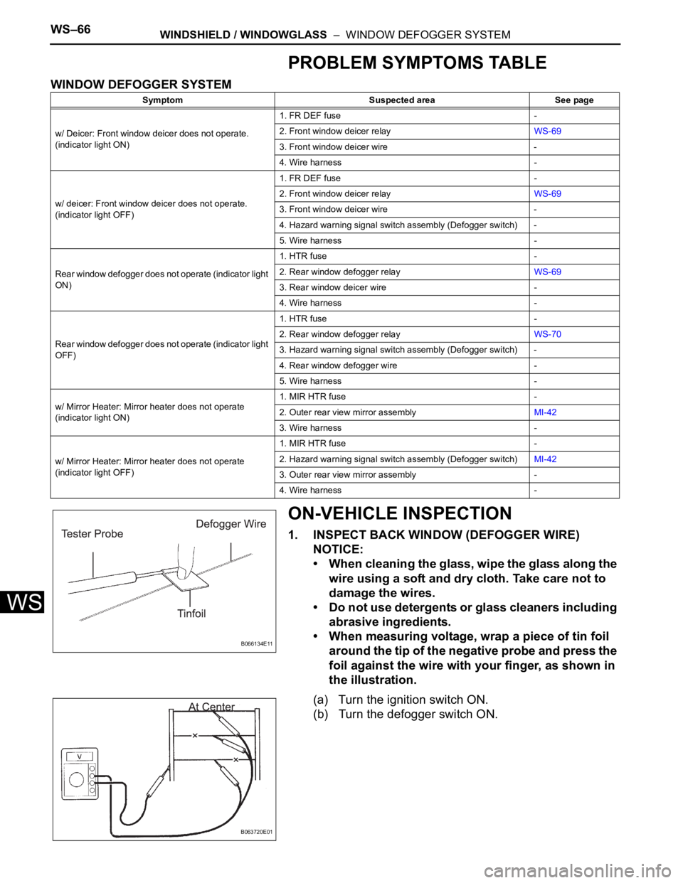
• When measuring voltage, wrap a piece of tin foil
around the tip of the negative probe and press the
foil against the wire with your finger, as shown in
the illustration.
(a) Turn the ignition switch ON.
(b) Turn the defogger switch ON.
Symptom Suspected area See page
w/ Deicer: Front window deicer does not operate.
(indicator light ON)1. FR DEF fuse -
2. Front window deicer relayWS-69
3. Front window deicer wire -
4. Wire harness -
w/ deicer: Front window deicer does not operate.
(indicator light OFF)1. FR DEF fuse -
2. Front window deicer relayWS-69
3. Front window deicer wire -
4. Hazard warning signal switch assembly (Defogger switch) -
5. Wire harness -
Rear window defogger does not operate (indicator light
ON)1. HTR fuse -
2. Rear window defogger relayWS-69
3. Rear window deicer wire -
4. Wire harness -
Rear window defogger does not operate (indicator light
OFF)1. HTR fuse -
2. Rear window defogger relayWS-70
3. Hazard warning signal switch assembly (Defogger switch) -
4. Rear window defogger wire -
5. Wire harness -
w/ Mirror Heater: Mirror heater does not operate
(indicator light ON)1. MIR HTR fuse -
2. Outer rear view mirror assemblyMI-42
3. Wire harness -
w/ Mirror Heater: Mirror heater does not operate
(indicator light OFF)1. MIR HTR fuse -
2. Hazard warning signal switch assembly (Defogger switch)MI-42
3. Outer rear view mirror assembly -
4. Wire harness -
B066134E11
B063720E01
Page 337 of 3000
2GR-FE ENGINE CONTROL SYSTEM – SFI SYSTEMES–409
ES
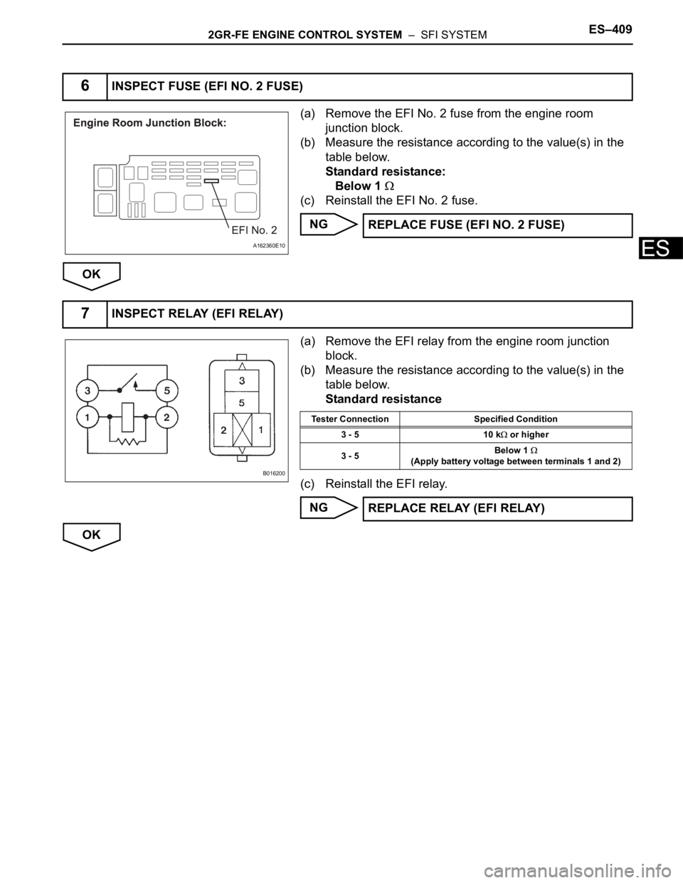
(a) Remove the EFI No. 2 fuse from the engine room
junction block.
(b) Measure the resistance according to the value(s) in the
table below.
Standard resistance:
Below 1
(c) Reinstall the EFI No. 2 fuse.
NG
OK
(a) Remove the EFI relay from the engine room junction
block.
(b) Measure the resistance according to the value(s) in the
table below.
Standard resistance
(c) Reinstall the EFI relay.
NG
OK
6INSPECT FUSE (EFI NO. 2 FUSE)
A162360E10
REPLACE FUSE (EFI NO. 2 FUSE)
7INSPECT RELAY (EFI RELAY)
B016200
Tester Connection Specified Condition
3 - 5 10 k
or higher
3 - 5Below 1
(Apply battery voltage between terminals 1 and 2)
REPLACE RELAY (EFI RELAY)
Page 338 of 3000
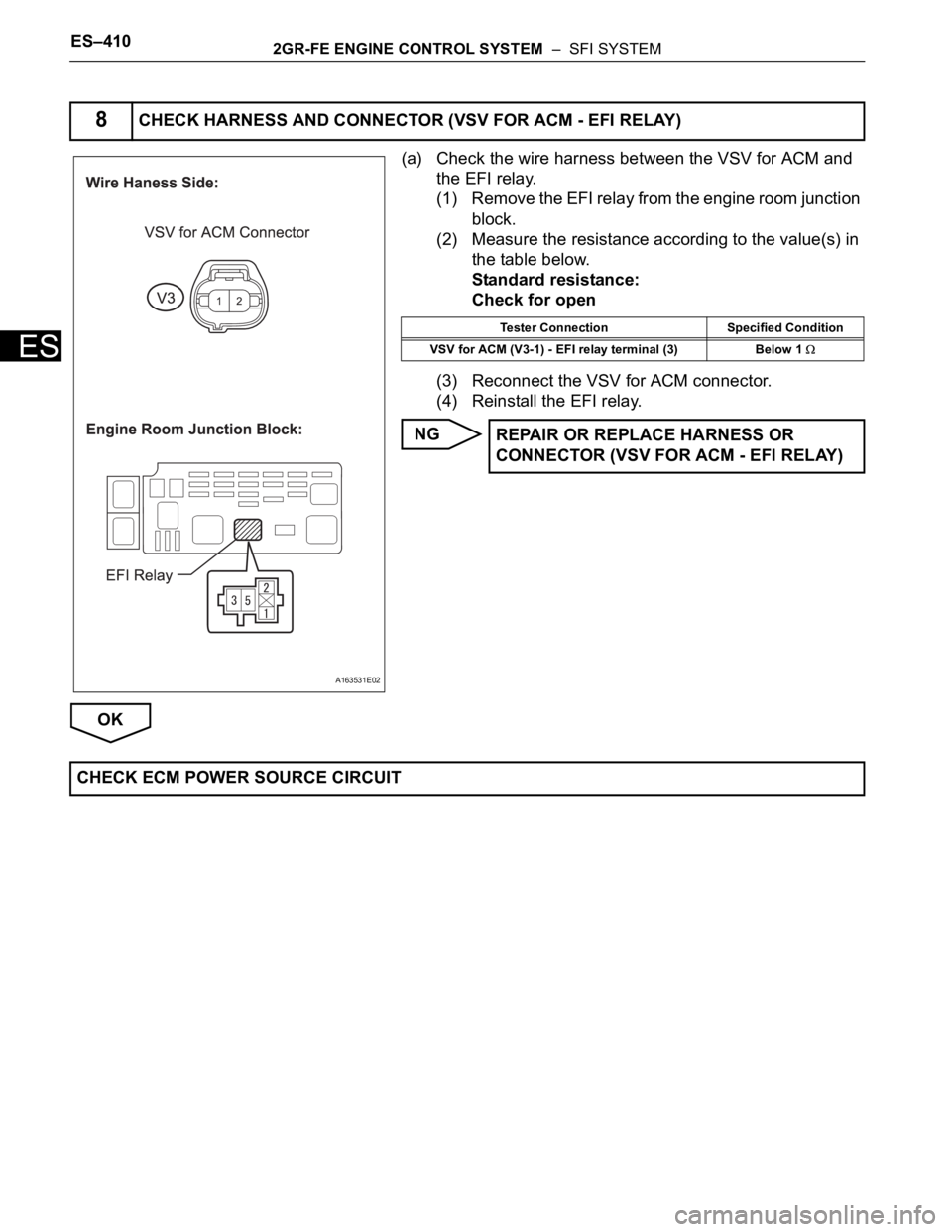
ES–4102GR-FE ENGINE CONTROL SYSTEM – SFI SYSTEM
ES
(a) Check the wire harness between the VSV for ACM and
the EFI relay.
(1) Remove the EFI relay from the engine room junction
block.
(2) Measure the resistance according to the value(s) in
the table below.
Standard resistance:
Check for open
(3) Reconnect the VSV for ACM connector.
(4) Reinstall the EFI relay.
NG
OK
8CHECK HARNESS AND CONNECTOR (VSV FOR ACM - EFI RELAY)
A163531E02
Tester Connection Specified Condition
VSV for ACM (V3-1) - EFI relay terminal (3) Below 1
REPAIR OR REPLACE HARNESS OR
CONNECTOR (VSV FOR ACM - EFI RELAY)
CHECK ECM POWER SOURCE CIRCUIT
Page 357 of 3000

2GR-FE ENGINE CONTROL SYSTEM – SFI SYSTEMES–31
ES
PROBLEM SYMPTOMS TABLE
HINT:
When a malfunction is not confirmed by a DTC (Diagnostic
Trouble Code) check and the cause of problem cannot be
identified through a basic inspection, troubleshoot according
to the priority order indicated in the table below.
SFI SYSTEM
Symptom Suspected Area See page
Engine does not crank (does not start)1. Immobilizer systemEI-2
2. StarterST-7
3. STARTER RelayST-14
4. Cranking holding function circuitES-461
No initial combustion (does not start)1. ECM power source circuitES-437
2. Ignition systemIG-5
3. Fuel pump control circuitES-451
4. InjectorFU-16
5. VC output circuitES-444
6. ECMES-498
Difficult to start (engine cranks normally)1. Electronic Throttle Control System (ETCS)ES-329
2. Fuel pump control circuitES-451
3. Ignition systemIG-5
4. Spark plugIG-7
5. CompressionEM-3
6. InjectorFU-16
7. VC output circuitES-444
Difficult to start with cold engine1. Cranking holding function circuitES-461
2. Electronic Throttle Control System (ETCS)ES-329
3. Fuel pump control circuitES-451
4. Spark plugIG-7
5. Ignition systemIG-6
6. InjectorFU-16
7. Engine coolant temperature sensorES-516
Difficult to start with hot engine1. Cooling fan systemCO-4
2. Cranking holding function circuitES-461
3. Electronic Throttle Control System (ETCS)ES-329
4. Fuel pump control circuitES-451
5. Spark plugIG-7
6. Ignition systemIG-5
7. InjectorFU-16
8. Engine coolant temperature sensorES-516
High engine idle speed (poor idling)1. Electronic Throttle Control System (ETCS)ES-329
2. ECM power source circuitES-437
3. A/C signal circuit (Compressor circuit) -
4. Acoustic Control Induction System (ACIS)ES-470
5. PCV hoseEC-15
6. ECMES-498