2007 TOYOTA SIENNA fuse
[x] Cancel search: fusePage 48 of 3000
IN–36INTRODUCTION – HOW TO TROUBLESHOOT ECU CONTROLLED SYSTEMS
IN
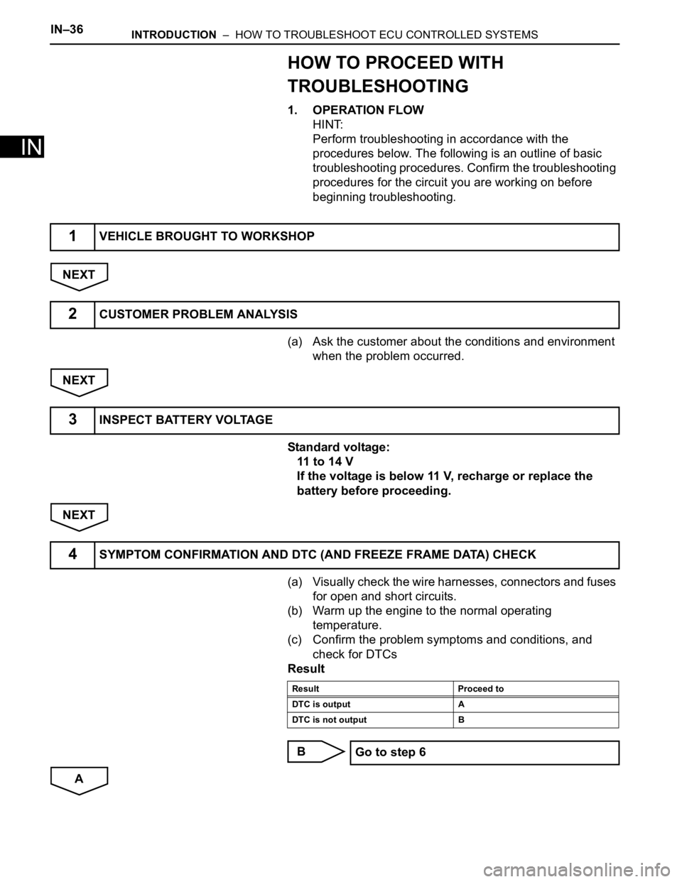
HOW TO PROCEED WITH
TROUBLESHOOTING
1. OPERATION FLOW
HINT:
Perform troubleshooting in accordance with the
procedures below. The following is an outline of basic
troubleshooting procedures. Confirm the troubleshooting
procedures for the circuit you are working on before
beginning troubleshooting.
NEXT
(a) Ask the customer about the conditions and environment
when the problem occurred.
NEXT
Standard voltage:
11 to 14 V
If the voltage is below 11 V, recharge or replace the
battery before proceeding.
NEXT
(a) Visually check the wire harnesses, connectors and fuses
for open and short circuits.
(b) Warm up the engine to the normal operating
temperature.
(c) Confirm the problem symptoms and conditions, and
check for DTCs
Result
B
A
1VEHICLE BROUGHT TO WORKSHOP
2CUSTOMER PROBLEM ANALYSIS
3INSPECT BATTERY VOLTAGE
4SYMPTOM CONFIRMATION AND DTC (AND FREEZE FRAME DATA) CHECK
Result Proceed to
DTC is output A
DTC is not output B
Go to step 6
Page 66 of 3000
IN–36INTRODUCTION – HOW TO TROUBLESHOOT ECU CONTROLLED SYSTEMS
IN
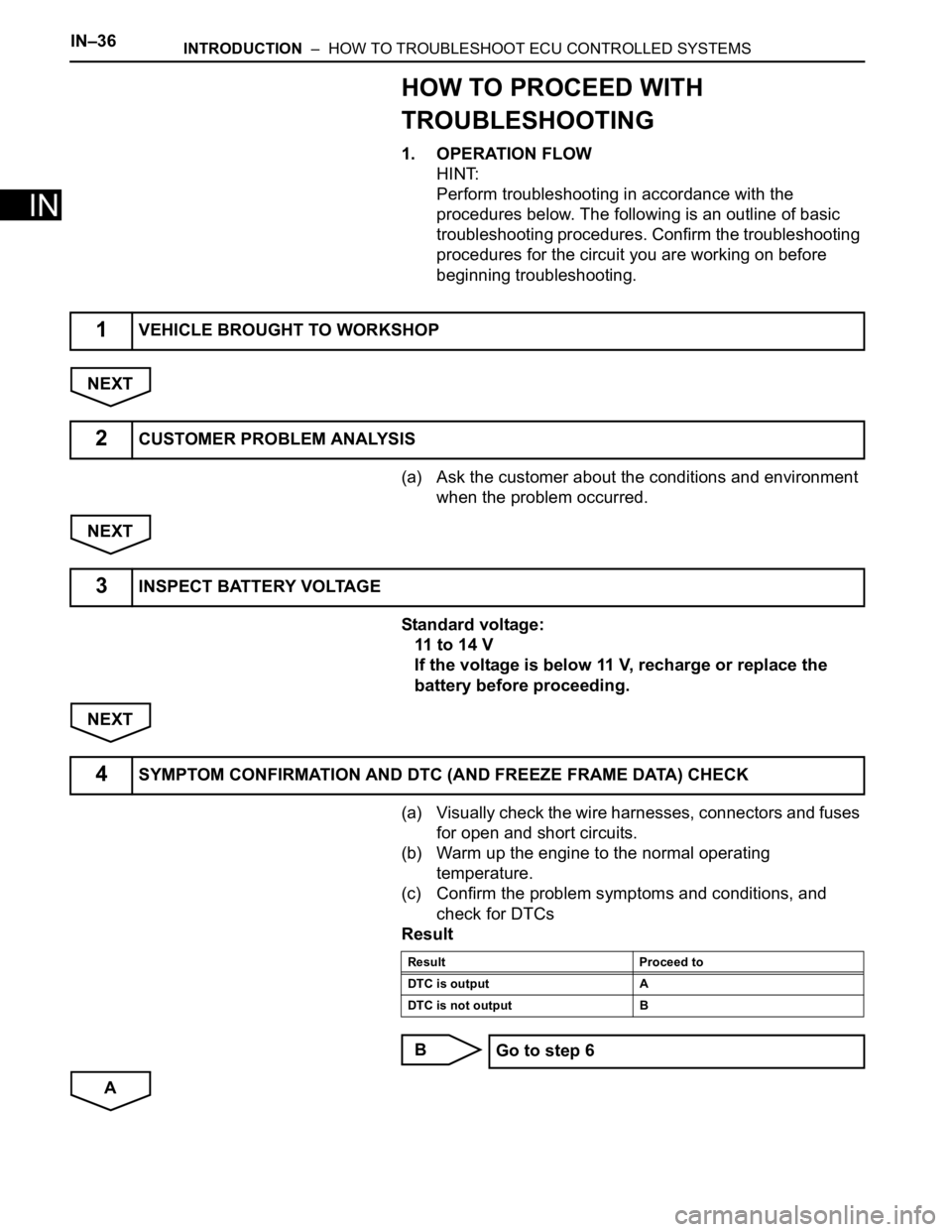
HOW TO PROCEED WITH
TROUBLESHOOTING
1. OPERATION FLOW
HINT:
Perform troubleshooting in accordance with the
procedures below. The following is an outline of basic
troubleshooting procedures. Confirm the troubleshooting
procedures for the circuit you are working on before
beginning troubleshooting.
NEXT
(a) Ask the customer about the conditions and environment
when the problem occurred.
NEXT
Standard voltage:
11 to 14 V
If the voltage is below 11 V, recharge or replace the
battery before proceeding.
NEXT
(a) Visually check the wire harnesses, connectors and fuses
for open and short circuits.
(b) Warm up the engine to the normal operating
temperature.
(c) Confirm the problem symptoms and conditions, and
check for DTCs
Result
B
A
1VEHICLE BROUGHT TO WORKSHOP
2CUSTOMER PROBLEM ANALYSIS
3INSPECT BATTERY VOLTAGE
4SYMPTOM CONFIRMATION AND DTC (AND FREEZE FRAME DATA) CHECK
Result Proceed to
DTC is output A
DTC is not output B
Go to step 6
Page 282 of 3000

WINDSHIELD / WINDOWGLASS – POWER WINDOW CONTROL SYSTEM (w/ Jam Protec-
tion Function)WS–7
WS
INITIALIZATION
NOTICE:
• Resetting the power window motor (initializing the
pulse sensor) is necessary when the battery terminal
is disconnected; when the master switch, wire
harness, power window regulator and power window
motor are replaced or removed/installed; or when the
fuses are replaced. AUTO operation function, jam
protection function and remote operation function via
the power window master switch do not operate
without resetting.
• If the AUTO switch (driver side switch) of the master
switch has been continuously operated for a long
time, the power window motor will stop so that no
additional load can be applied to the motor.
Continuing to operate the switch even after the motor
has stopped will cause the switch to blink while
restricting the AUTO UP/DOWN function and the
remote UP/DOWN function. If this happens, reset the
motor again after several minutes have passed.
• Whenever disconnecting the battery terminal, reset all
the other systems besides the power window control
system.
1. RESET POWER WINDOW REGULATOR MOTOR
(DRIVER SIDE)
(a) Turn the ignition switch ON.
(b) Halfway open the power window by pressing the
power window switch.
(c) Fully pull up the switch until the power window is
fully closed and continue to hold the switch for
approx. 1 second after the power window is fully
closed.
(d) Check that the AUTO UP/DOWN function operates
normally.
If the AUTO UP/DOWN function operates normally,
reset operations have been completed at this time.
If not normal, follow steps below.
(1) Disconnect the negative battery terminal for 10
seconds.
(2) Connect the battery terminal.
(3) Perform the above steps (a) to (d) again.
HINT:
If operation is normal, reset operations have
been completed at this time. If not normal, follow
steps (4) to (7).
(4) Turn the ignition switch ON.
(5) Halfway open the power window by pressing the
power window switch.
(6) Fully pull up the switch until the power window is
fully closed and continue to hold the switch for
approx. 12 seconds after the power window is
fully closed.
(7) Check that the AUTO UP/DOWN function
operates normally.
Page 283 of 3000
WS–66WINDSHIELD / WINDOWGLASS – WINDOW DEFOGGER SYSTEM
WS
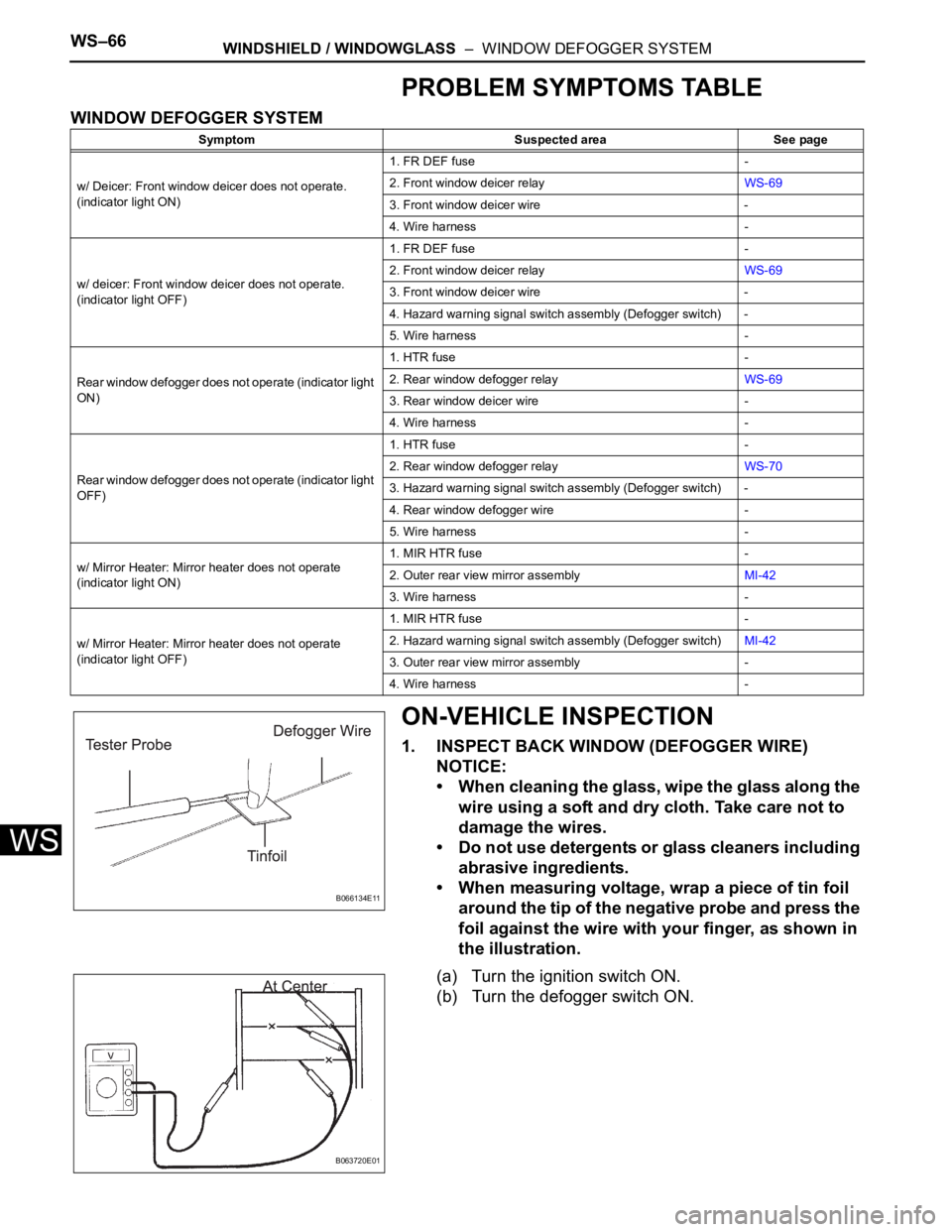
PROBLEM SYMPTOMS TABLE
WINDOW DEFOGGER SYSTEM
ON-VEHICLE INSPECTION
1. INSPECT BACK WINDOW (DEFOGGER WIRE)
NOTICE:
• When cleaning the glass, wipe the glass along the
wire using a soft and dry cloth. Take care not to
damage the wires.
• Do not use detergents or glass cleaners including
abrasive ingredients.
• When measuring voltage, wrap a piece of tin foil
around the tip of the negative probe and press the
foil against the wire with your finger, as shown in
the illustration.
(a) Turn the ignition switch ON.
(b) Turn the defogger switch ON.
Symptom Suspected area See page
w/ Deicer: Front window deicer does not operate.
(indicator light ON)1. FR DEF fuse -
2. Front window deicer relayWS-69
3. Front window deicer wire -
4. Wire harness -
w/ deicer: Front window deicer does not operate.
(indicator light OFF)1. FR DEF fuse -
2. Front window deicer relayWS-69
3. Front window deicer wire -
4. Hazard warning signal switch assembly (Defogger switch) -
5. Wire harness -
Rear window defogger does not operate (indicator light
ON)1. HTR fuse -
2. Rear window defogger relayWS-69
3. Rear window deicer wire -
4. Wire harness -
Rear window defogger does not operate (indicator light
OFF)1. HTR fuse -
2. Rear window defogger relayWS-70
3. Hazard warning signal switch assembly (Defogger switch) -
4. Rear window defogger wire -
5. Wire harness -
w/ Mirror Heater: Mirror heater does not operate
(indicator light ON)1. MIR HTR fuse -
2. Outer rear view mirror assemblyMI-42
3. Wire harness -
w/ Mirror Heater: Mirror heater does not operate
(indicator light OFF)1. MIR HTR fuse -
2. Hazard warning signal switch assembly (Defogger switch)MI-42
3. Outer rear view mirror assembly -
4. Wire harness -
B066134E11
B063720E01
Page 337 of 3000
2GR-FE ENGINE CONTROL SYSTEM – SFI SYSTEMES–409
ES
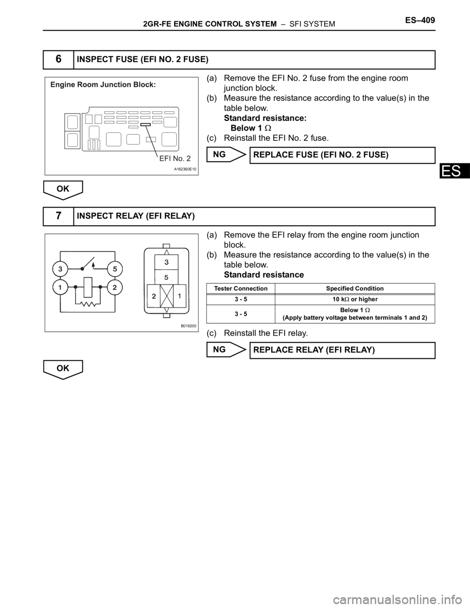
(a) Remove the EFI No. 2 fuse from the engine room
junction block.
(b) Measure the resistance according to the value(s) in the
table below.
Standard resistance:
Below 1
(c) Reinstall the EFI No. 2 fuse.
NG
OK
(a) Remove the EFI relay from the engine room junction
block.
(b) Measure the resistance according to the value(s) in the
table below.
Standard resistance
(c) Reinstall the EFI relay.
NG
OK
6INSPECT FUSE (EFI NO. 2 FUSE)
A162360E10
REPLACE FUSE (EFI NO. 2 FUSE)
7INSPECT RELAY (EFI RELAY)
B016200
Tester Connection Specified Condition
3 - 5 10 k
or higher
3 - 5Below 1
(Apply battery voltage between terminals 1 and 2)
REPLACE RELAY (EFI RELAY)
Page 352 of 3000

ES–262GR-FE ENGINE CONTROL SYSTEM – SFI SYSTEM
ES
READINESS MONITOR DRIVE
PAT T E R N
1. PURPOSE OF READINESS TESTS
• The On-Board Diagnostic (OBD II) system is
designed to monitor the performance of emission-
related components, and indicate any detected
abnormalities with DTCs (Diagnostic Trouble Codes).
Since various components need to be monitored in
different driving conditions, the OBD II system is
designed to run separate monitoring programs called
Readiness Monitors.
• The intelligent tester's software must be version 9.0 or
newer to view the Readiness Monitor status. To view
the status, select the following menu items:
DIAGNOSIS / ENHANCED OBD II / MONITOR INFO
/ MONITOR STATUS.
• When the Readiness Monitor status reads COMPL
(complete), the necessary conditions have been met
for running the performance tests for that Readiness
Monitor.
• A generic OBD II scan tool can also be used to view
the Readiness Monitor status.
HINT:
Many Inspection and Maintenance (I/M) programs
require a vehicle's Readiness Monitor status to show
COMPL before beginning emission tests.
The Readiness Monitor will be reset to INCMPL
(incomplete) if:
• The ECM has lost battery power or broken a fuse.
• DTCs have been cleared.
• The conditions for running the Readiness Monitor
have not been met.
If the Readiness Monitor status shows INCMPL, follow
the appropriate Readiness Monitor Drive Pattern to
change the status to COMPL.
CAUTION:
Strictly observe posted speed limits, traffic laws, and
road conditions when performing these drive
patterns.
NOTICE:
These drive patterns represent the fastest method of
satisfying all conditions necessary to achieve
complete status for each specific Readiness
Monitor.
In the event of a drive pattern being interrupted
(possibly due to factors such as traffic conditions),
the drive pattern can be resumed. In most cases, the
Readiness Monitor will still achieve complete status
upon completion of the drive pattern.
To ensure completion of the Readiness Monitors,
avoid sudden changes in vehicle load and speed
(driving up and down hills and/or sudden
acceleration).
Page 363 of 3000
2GR-FE ENGINE CONTROL SYSTEM – SFI SYSTEMES–45
ES
DTC CHECK / CLEAR
NOTICE:
All the stored DTCs and freeze frame data are erased if:
1) the ECM is changed from normal mode to check mode
or vice versa; or 2) the ignition switch is turned from ON
to ACC or off while in check mode.
Before changing modes, always check and make a note
of any DTCs and freeze frame data.
HINT:
• DTCs which are stored in the ECM can be displayed on an
intelligent tester. An intelligent tester can display current
and pending DTCs.
• Some DTCs are not set if the ECM does not detect the
same malfunction again during the second consecutive
driving cycle. However, such malfunctions, detected on
only one occasion, are stored as pending DTCs.
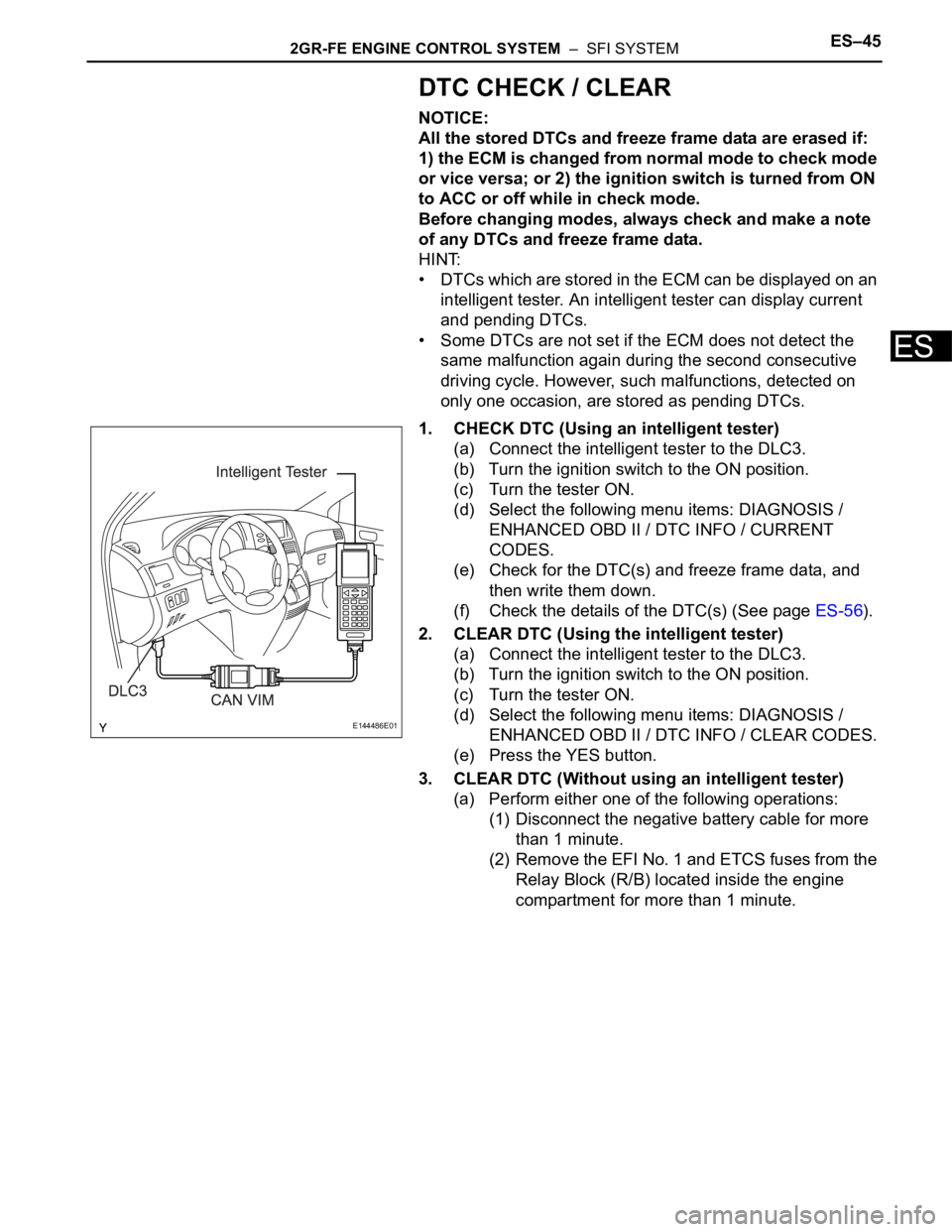
1. CHECK DTC (Using an intelligent tester)
(a) Connect the intelligent tester to the DLC3.
(b) Turn the ignition switch to the ON position.
(c) Turn the tester ON.
(d) Select the following menu items: DIAGNOSIS /
ENHANCED OBD II / DTC INFO / CURRENT
CODES.
(e) Check for the DTC(s) and freeze frame data, and
then write them down.
(f) Check the details of the DTC(s) (See page ES-56).
2. CLEAR DTC (Using the intelligent tester)
(a) Connect the intelligent tester to the DLC3.
(b) Turn the ignition switch to the ON position.
(c) Turn the tester ON.
(d) Select the following menu items: DIAGNOSIS /
ENHANCED OBD II / DTC INFO / CLEAR CODES.
(e) Press the YES button.
3. CLEAR DTC (Without using an intelligent tester)
(a) Perform either one of the following operations:
(1) Disconnect the negative battery cable for more
than 1 minute.
(2) Remove the EFI No. 1 and ETCS fuses from the
Relay Block (R/B) located inside the engine
compartment for more than 1 minute.
E144486E01
Page 382 of 3000
ES–762GR-FE ENGINE CONTROL SYSTEM – SFI SYSTEM
ES
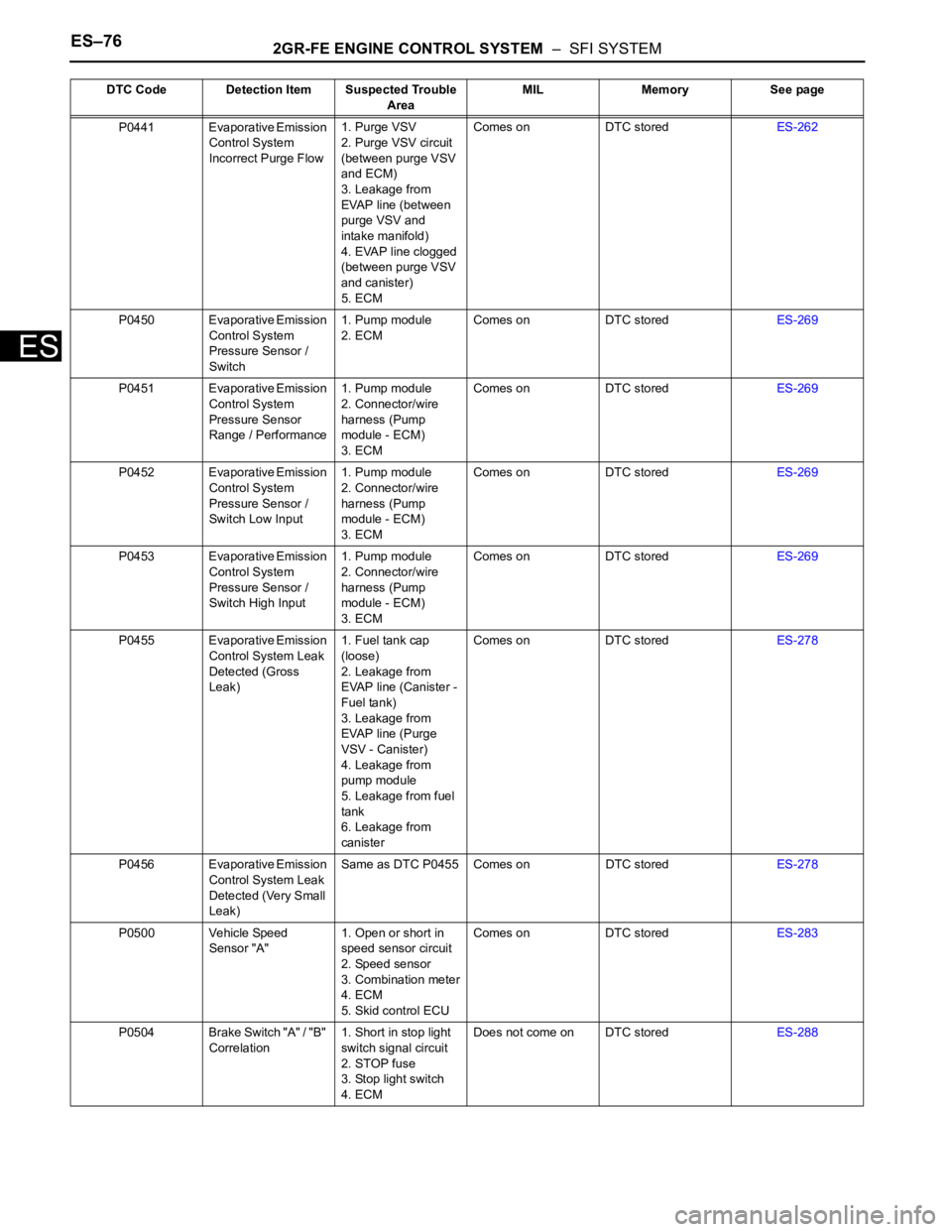
P0441 Evaporative Emission
Control System
Incorrect Purge Flow1. Purge VSV
2. Purge VSV circuit
(between purge VSV
and ECM)
3. Leakage from
EVAP line (between
purge VSV and
intake manifold)
4. EVAP line clogged
(between purge VSV
and canister)
5. ECMComes on DTC storedES-262
P0450 Evaporative Emission
Control System
Pressure Sensor /
Switch1. Pump module
2. ECMComes on DTC storedES-269
P0451 Evaporative Emission
Control System
Pressure Sensor
Range / Performance1. Pump module
2. Connector/wire
harness (Pump
module - ECM)
3. ECMComes on DTC storedES-269
P0452 Evaporative Emission
Control System
Pressure Sensor /
Switch Low Input1. Pump module
2. Connector/wire
harness (Pump
module - ECM)
3. ECMComes on DTC storedES-269
P0453 Evaporative Emission
Control System
Pressure Sensor /
Switch High Input1. Pump module
2. Connector/wire
harness (Pump
module - ECM)
3. ECMComes on DTC storedES-269
P0455 Evaporative Emission
Control System Leak
Detected (Gross
Leak)1. Fuel tank cap
(loose)
2. Leakage from
EVAP line (Canister -
Fuel tank)
3. Leakage from
EVAP line (Purge
VSV - Canister)
4. Leakage from
pump module
5. Leakage from fuel
tank
6. Leakage from
canisterComes on DTC storedES-278
P0456 Evaporative Emission
Control System Leak
Detected (Very Small
Leak)Same as DTC P0455 Comes on DTC storedES-278
P0500 Vehicle Speed
Sensor "A"1. Open or short in
speed sensor circuit
2. Speed sensor
3. Combination meter
4. ECM
5. Skid control ECUComes on DTC storedES-283
P0504 Brake Switch "A" / "B"
Correlation1. Short in stop light
switch signal circuit
2. STOP fuse
3. Stop light switch
4. ECMDoes not come on DTC storedES-288 DTC Code Detection Item Suspected Trouble
AreaMIL Memory See page