Page 1552 of 3000
U151E AUTOMATIC TRANSAXLE – AUTOMATIC TRANSAXLE SYSTEMAX–33
AX
(b) When not using the OBD II scan tool or intelligent
tester: Clearing the DTCs.
(1) Disconnect the battery terminal or remove the
EFI and ETCS fuses from the engine room J/B
for 60 seconds or more. However, if you
disconnect the battery terminal, perform do the
"INITIALIZE" procedure.
Page 1709 of 3000
U151F AUTOMATIC TRANSAXLE – AUTOMATIC TRANSAXLE SYSTEMAX–33
AX
(b) When not using the OBD II scan tool or intelligent
tester: Clearing the DTCs.
(1) Disconnect the battery terminal or remove the
EFI and ETCS fuses from the engine room J/B
for 60 seconds or more. However, if you
disconnect the battery terminal, perform do the
"INITIALIZE" procedure.
Page 1711 of 3000

U151F AUTOMATIC TRANSAXLE – AUTOMATIC TRANSAXLE SYSTEMAX–35
AX
(11)(See page AX-35) to confirm the details of the
DTCs.
2. DTC CLEAR
(a) When using the OBD II scan tool or intelligent
tester: Clearing the DTCs.
(1) Connect the intelligent tester together with the
CAN VIM (controller area network vehicle
interface module) to the DLC3.
(2) Turn the ignition switch to the ON position and
turn the OBD II scan tool or the intelligent tester
main switch on.
(3) When you use intelligent tester: Select the item
"DIAGNOSIS/ENHANCED OBD II/DTC INFO/
CLEAR CODES [YES] button".
HINT:
When operating the OBD II scan tool (complying
with SAE J1978) or intelligent tester to erase the
codes, the DTCs and freeze frame data will be
erased. (See the OBD II scan tool's instruction
book for operating instructions.)
(b) When not using the OBD II scan tool or intelligent
tester: Clearing the DTCs.
(1) Disconnect the battery cable or remove the EFI
and ETCS fuses from the engine room J/B for 60
seconds or more. However, if you disconnect the
battery cable, perform do the "INITIALIZE"
procedure.
Page 1855 of 3000
U151F AUTOMATIC TRANSAXLE – AUTOMATIC TRANSAXLE SYSTEMAX–33
AX
(b) When not using the OBD II scan tool or intelligent
tester: Clearing the DTCs.
(1) Disconnect the battery terminal or remove the
EFI and ETCS fuses from the engine room J/B
for 60 seconds or more. However, if you
disconnect the battery terminal, perform do the
"INITIALIZE" procedure.
Page 2278 of 3000

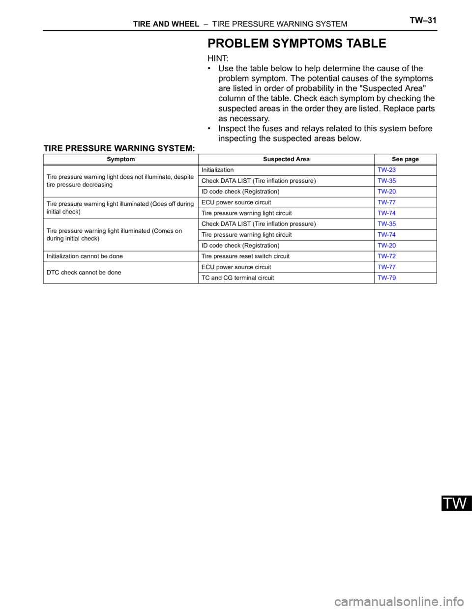
TIRE AND WHEEL – TIRE PRESSURE WARNING SYSTEMTW–31
TW
PROBLEM SYMPTOMS TABLE
HINT:
• Use the table below to help determine the cause of the
problem symptom. The potential causes of the symptoms
are listed in order of probability in the "Suspected Area"
column of the table. Check each symptom by checking the
suspected areas in the order they are listed. Replace parts
as necessary.
• Inspect the fuses and relays related to this system before
inspecting the suspected areas below.
TIRE PRESSURE WARNING SYSTEM:
Symptom Suspected Area See page
Tire pressure warning light does not illuminate, despite
tire pressure decreasingInitializationTW-23
Check DATA LIST (Tire inflation pressure)TW-35
ID code check (Registration)TW-20
Tire pressure warning light illuminated (Goes off during
initial check)ECU power source circuitTW-77
Tire pressure warning light circuitTW-74
Tire pressure warning light illuminated (Comes on
during initial check)Check DATA LIST (Tire inflation pressure)TW-35
Tire pressure warning light circuitTW-74
ID code check (Registration)TW-20
Initialization cannot be done Tire pressure reset switch circuitTW-72
DTC check cannot be doneECU power source circuitTW-77
TC and CG terminal circuitTW-79
Page 2322 of 3000
TW–80TIRE AND WHEEL – TIRE PRESSURE WARNING SYSTEM
TW
DESCRIPTION
This is the power source for the tire pressure warning ECU.
WIRING DIAGRAM
INSPECTION PROCEDURE
NOTICE:
When replacing the tire pressure warning ECU, read the transmitter IDs stored in the old ECU
using the intelligent tester and write them down before removal.
It is necessary to register an ID code after replacing the tire pressure warning valve and
transmitter and/or the tire pressure warning ECU (See page TW-20).
(a) Remove the ECU-IG fuse from the instrument panel
junction block.
(b) Measure the resistance of the fuse.
Standard resistance:
Below 1
NG
ECU Power Source Circuit
1INSPECT FUSE (ECU-IG)
C162809E01
REPLACE FUSE
Page 2346 of 3000

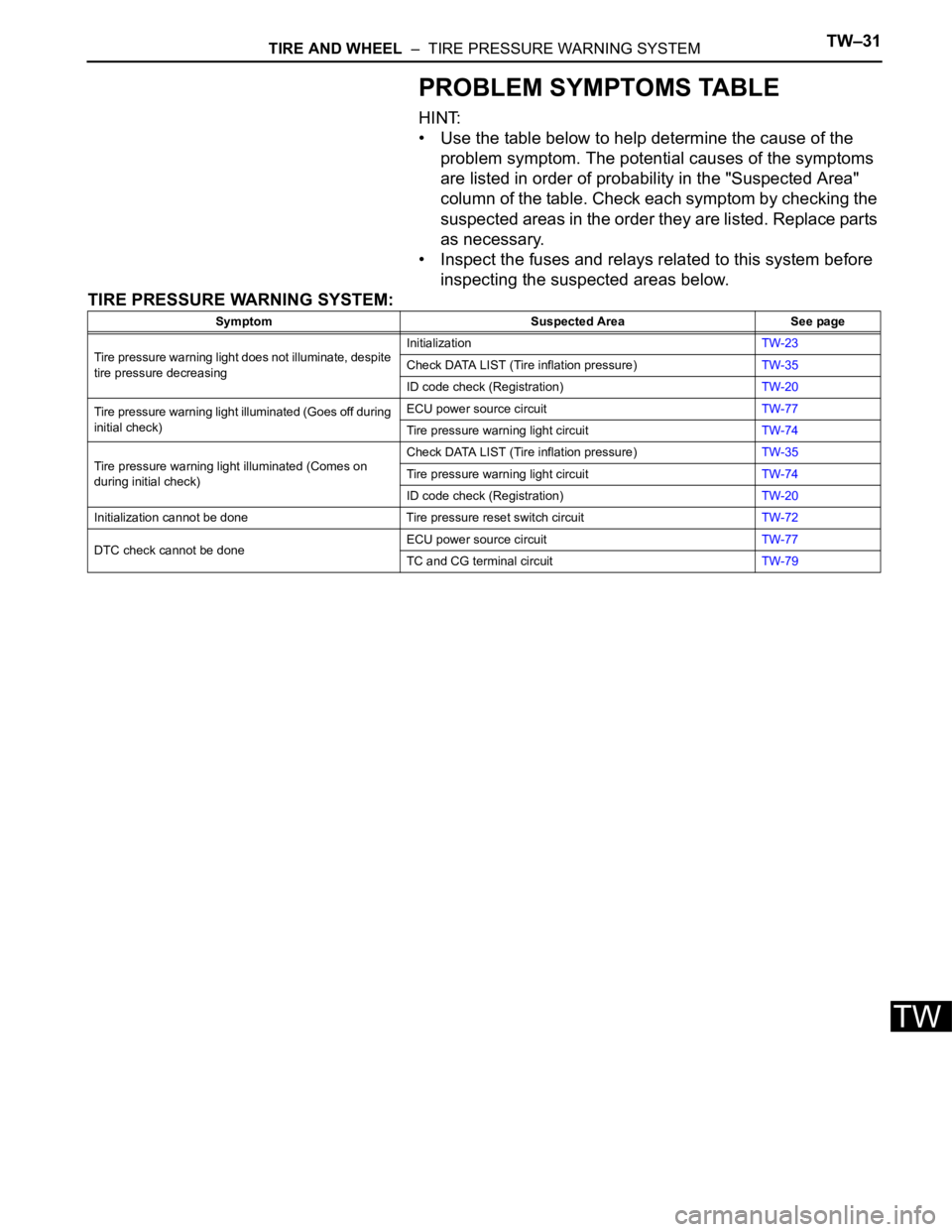
TIRE AND WHEEL – TIRE PRESSURE WARNING SYSTEMTW–31
TW
PROBLEM SYMPTOMS TABLE
HINT:
• Use the table below to help determine the cause of the
problem symptom. The potential causes of the symptoms
are listed in order of probability in the "Suspected Area"
column of the table. Check each symptom by checking the
suspected areas in the order they are listed. Replace parts
as necessary.
• Inspect the fuses and relays related to this system before
inspecting the suspected areas below.
TIRE PRESSURE WARNING SYSTEM:
Symptom Suspected Area See page
Tire pressure warning light does not illuminate, despite
tire pressure decreasingInitializationTW-23
Check DATA LIST (Tire inflation pressure)TW-35
ID code check (Registration)TW-20
Tire pressure warning light illuminated (Goes off during
initial check)ECU power source circuitTW-77
Tire pressure warning light circuitTW-74
Tire pressure warning light illuminated (Comes on
during initial check)Check DATA LIST (Tire inflation pressure)TW-35
Tire pressure warning light circuitTW-74
ID code check (Registration)TW-20
Initialization cannot be done Tire pressure reset switch circuitTW-72
DTC check cannot be doneECU power source circuitTW-77
TC and CG terminal circuitTW-79
Page 2360 of 3000

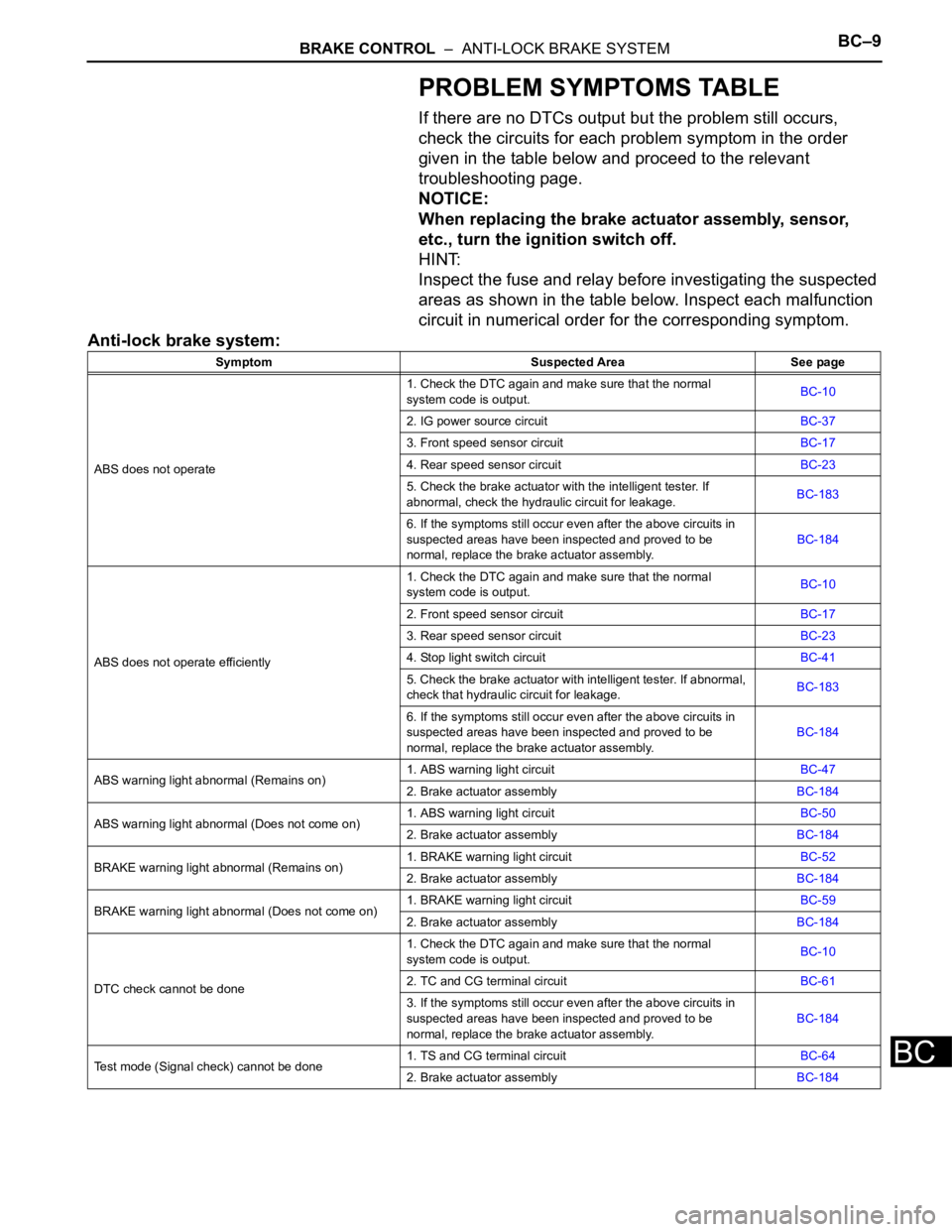
BRAKE CONTROL – ANTI-LOCK BRAKE SYSTEMBC–9
BC
PROBLEM SYMPTOMS TABLE
If there are no DTCs output but the problem still occurs,
check the circuits for each problem symptom in the order
given in the table below and proceed to the relevant
troubleshooting page.
NOTICE:
When replacing the brake actuator assembly, sensor,
etc., turn the ignition switch off.
HINT:
Inspect the fuse and relay before investigating the suspected
areas as shown in the table below. Inspect each malfunction
circuit in numerical order for the corresponding symptom.
Anti-lock brake system:
Symptom Suspected Area See page
ABS does not operate1. Check the DTC again and make sure that the normal
system code is output.BC-10
2. IG power source circuitBC-37
3. Front speed sensor circuitBC-17
4. Rear speed sensor circuitBC-23
5. Check the brake actuator with the intelligent tester. If
abnormal, check the hydraulic circuit for leakage.BC-183
6. If the symptoms still occur even after the above circuits in
suspected areas have been inspected and proved to be
normal, replace the brake actuator assembly.BC-184
ABS does not operate efficiently1. Check the DTC again and make sure that the normal
system code is output.BC-10
2. Front speed sensor circuitBC-17
3. Rear speed sensor circuitBC-23
4. Stop light switch circuitBC-41
5. Check the brake actuator with intelligent tester. If abnormal,
check that hydraulic circuit for leakage.BC-183
6. If the symptoms still occur even after the above circuits in
suspected areas have been inspected and proved to be
normal, replace the brake actuator assembly.BC-184
ABS warning light abnormal (Remains on)1. ABS warning light circuitBC-47
2. Brake actuator assemblyBC-184
ABS warning light abnormal (Does not come on)1. ABS warning light circuitBC-50
2. Brake actuator assemblyBC-184
BRAKE warning light abnormal (Remains on)1. BRAKE warning light circuitBC-52
2. Brake actuator assemblyBC-184
BRAKE warning light abnormal (Does not come on)1. BRAKE warning light circuitBC-59
2. Brake actuator assemblyBC-184
DTC check cannot be done1. Check the DTC again and make sure that the normal
system code is output.BC-10
2. TC and CG terminal circuitBC-61
3. If the symptoms still occur even after the above circuits in
suspected areas have been inspected and proved to be
normal, replace the brake actuator assembly.BC-184
Test mode (Signal check) cannot be done1. TS and CG terminal circuitBC-64
2. Brake actuator assemblyBC-184