2007 TOYOTA SIENNA fuse
[x] Cancel search: fusePage 383 of 3000
2GR-FE ENGINE CONTROL SYSTEM – SFI SYSTEMES–77
ES
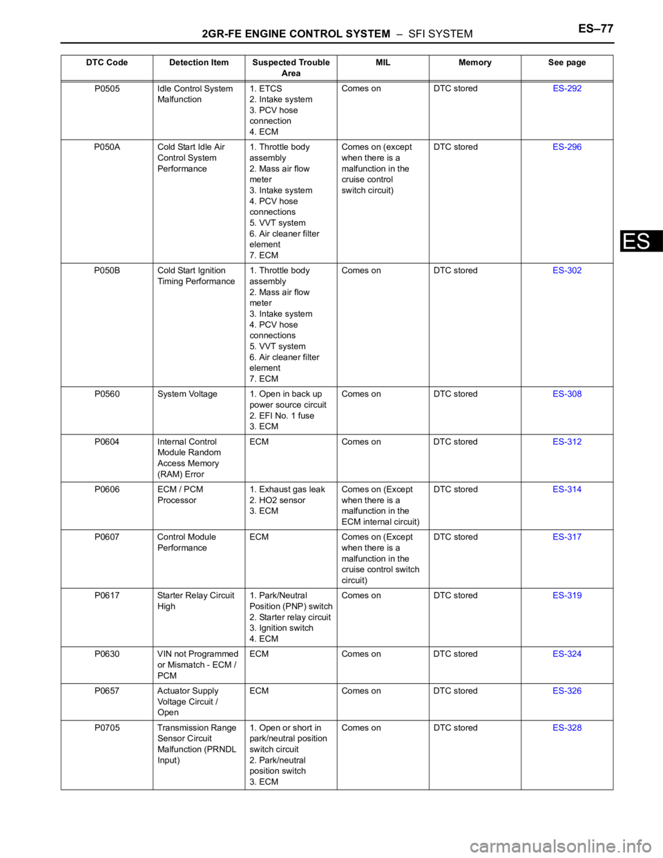
P0505 Idle Control System
Malfunction1. ETCS
2. Intake system
3. PCV hose
connection
4. ECMComes on DTC storedES-292
P050A Cold Start Idle Air
Control System
Performance1. Throttle body
assembly
2. Mass air flow
meter
3. Intake system
4. PCV hose
connections
5. VVT system
6. Air cleaner filter
element
7. ECMComes on (except
when there is a
malfunction in the
cruise control
switch circuit)DTC storedES-296
P050B Cold Start Ignition
Timing Performance1. Throttle body
assembly
2. Mass air flow
meter
3. Intake system
4. PCV hose
connections
5. VVT system
6. Air cleaner filter
element
7. ECMComes on DTC storedES-302
P0560 System Voltage 1. Open in back up
power source circuit
2. EFI No. 1 fuse
3. ECMComes on DTC storedES-308
P0604 Internal Control
Module Random
Access Memory
(RAM) ErrorECM Comes on DTC storedES-312
P0606 ECM / PCM
Processor1. Exhaust gas leak
2. HO2 sensor
3. ECMComes on (Except
when there is a
malfunction in the
ECM internal circuit)DTC storedES-314
P0607 Control Module
PerformanceECM Comes on (Except
when there is a
malfunction in the
cruise control switch
circuit)DTC storedES-317
P0617 Starter Relay Circuit
High1. Park/Neutral
Position (PNP) switch
2. Starter relay circuit
3. Ignition switch
4. ECMComes on DTC storedES-319
P0630 VIN not Programmed
or Mismatch - ECM /
PCMECM Comes on DTC storedES-324
P0657 Actuator Supply
Voltage Circuit /
OpenECM Comes on DTC storedES-326
P0705 Transmission Range
Sensor Circuit
Malfunction (PRNDL
Input)1. Open or short in
park/neutral position
switch circuit
2. Park/neutral
position switch
3. ECMComes on DTC storedES-328 DTC Code Detection Item Suspected Trouble
AreaMIL Memory See page
Page 384 of 3000
ES–782GR-FE ENGINE CONTROL SYSTEM – SFI SYSTEM
ES
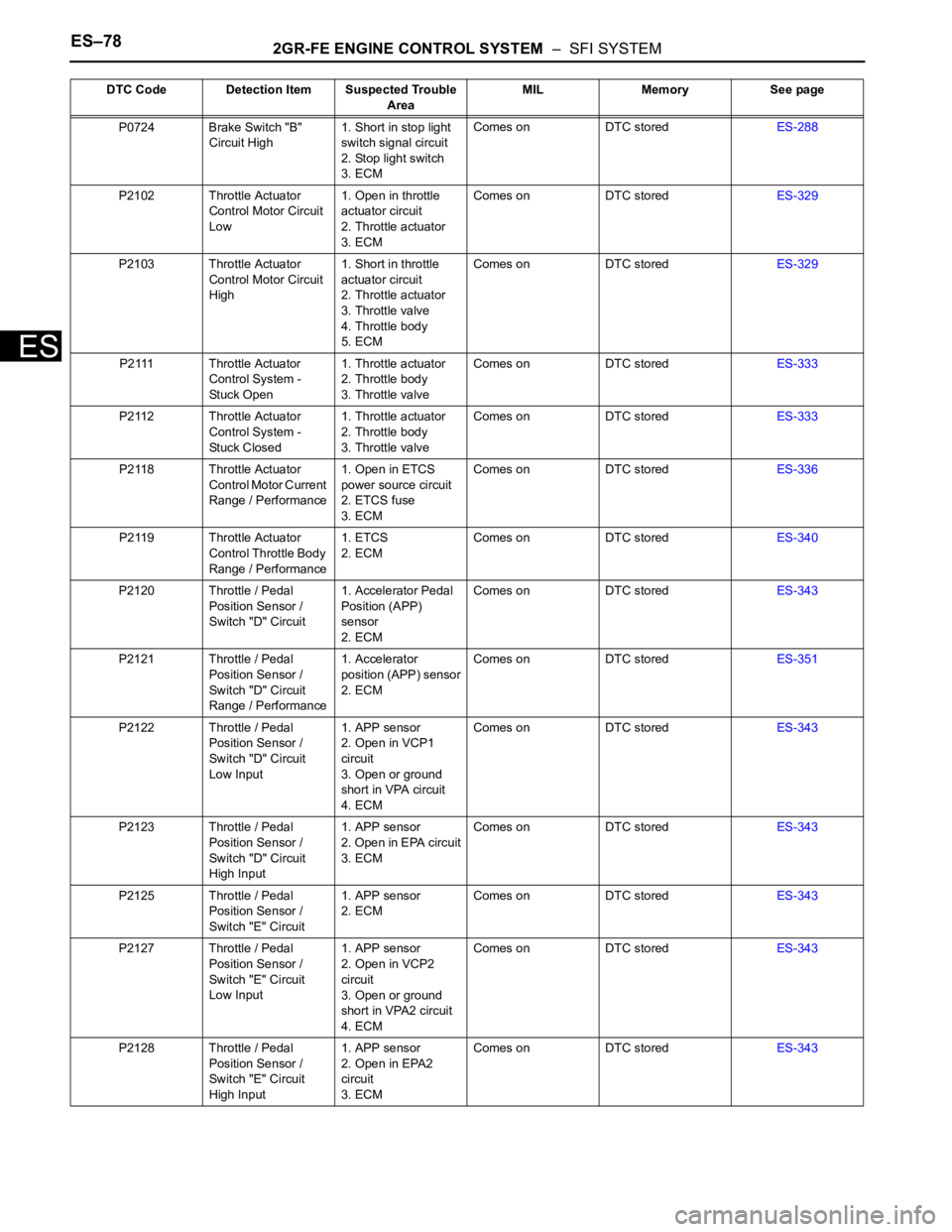
P0724 Brake Switch "B"
Circuit High1. Short in stop light
switch signal circuit
2. Stop light switch
3. ECMComes on DTC storedES-288
P2102 Throttle Actuator
Control Motor Circuit
Low1. Open in throttle
actuator circuit
2. Throttle actuator
3. ECMComes on DTC storedES-329
P2103 Throttle Actuator
Control Motor Circuit
High1. Short in throttle
actuator circuit
2. Throttle actuator
3. Throttle valve
4. Throttle body
5. ECMComes on DTC storedES-329
P2111 Throttle Actuator
Control System -
Stuck Open1. Throttle actuator
2. Throttle body
3. Throttle valveComes on DTC storedES-333
P2112 Throttle Actuator
Control System -
Stuck Closed1. Throttle actuator
2. Throttle body
3. Throttle valveComes on DTC storedES-333
P2118 Throttle Actuator
Control Motor Current
Range / Performance1. Open in ETCS
power source circuit
2. ETCS fuse
3. ECMComes on DTC storedES-336
P2119 Throttle Actuator
Control Throttle Body
Range / Performance1. ETCS
2. ECMComes on DTC storedES-340
P2120 Throttle / Pedal
Position Sensor /
Switch "D" Circuit1. Accelerator Pedal
Position (APP)
sensor
2. ECMComes on DTC storedES-343
P2121 Throttle / Pedal
Position Sensor /
Switch "D" Circuit
Range / Performance1. Accelerator
position (APP) sensor
2. ECMComes on DTC storedES-351
P2122 Throttle / Pedal
Position Sensor /
Switch "D" Circuit
Low Input1. APP sensor
2. Open in VCP1
circuit
3. Open or ground
short in VPA circuit
4. ECMComes on DTC storedES-343
P2123 Throttle / Pedal
Position Sensor /
Switch "D" Circuit
High Input1. APP sensor
2. Open in EPA circuit
3. ECMComes on DTC storedES-343
P2125 Throttle / Pedal
Position Sensor /
Switch "E" Circuit1. APP sensor
2. ECMComes on DTC storedES-343
P2127 Throttle / Pedal
Position Sensor /
Switch "E" Circuit
Low Input1. APP sensor
2. Open in VCP2
circuit
3. Open or ground
short in VPA2 circuit
4. ECMComes on DTC storedES-343
P2128 Throttle / Pedal
Position Sensor /
Switch "E" Circuit
High Input1. APP sensor
2. Open in EPA2
circuit
3. ECMComes on DTC storedES-343 DTC Code Detection Item Suspected Trouble
AreaMIL Memory See page
Page 419 of 3000
2GR-FE ENGINE CONTROL SYSTEM – SFI SYSTEMES–113
ES
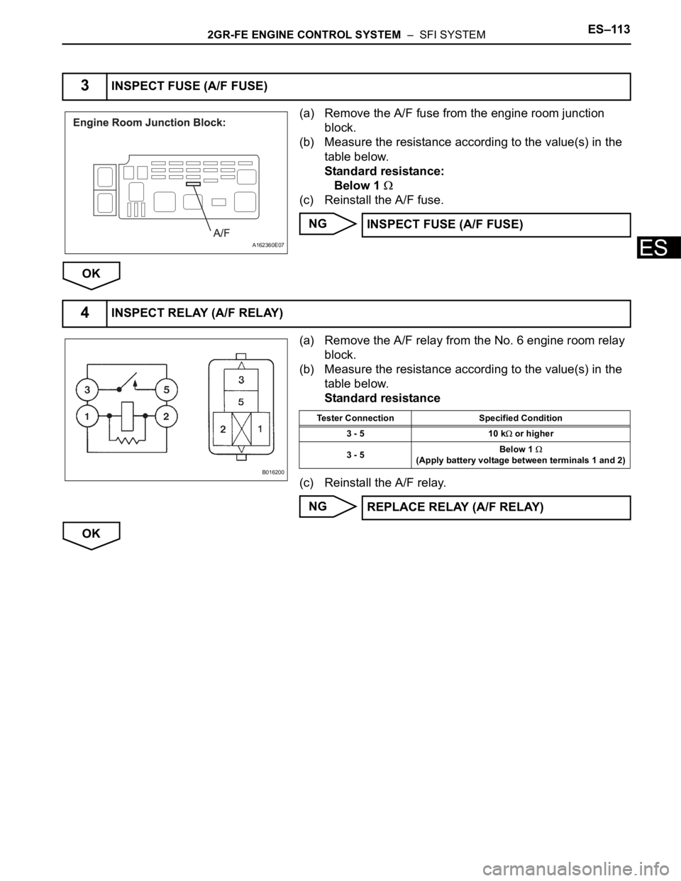
(a) Remove the A/F fuse from the engine room junction
block.
(b) Measure the resistance according to the value(s) in the
table below.
Standard resistance:
Below 1
(c) Reinstall the A/F fuse.
NG
OK
(a) Remove the A/F relay from the No. 6 engine room relay
block.
(b) Measure the resistance according to the value(s) in the
table below.
Standard resistance
(c) Reinstall the A/F relay.
NG
OK
3INSPECT FUSE (A/F FUSE)
A162360E07
INSPECT FUSE (A/F FUSE)
4INSPECT RELAY (A/F RELAY)
B016200
Tester Connection Specified Condition
3 - 5 10 k
or higher
3 - 5Below 1
(Apply battery voltage between terminals 1 and 2)
REPLACE RELAY (A/F RELAY)
Page 427 of 3000
2GR-FE ENGINE CONTROL SYSTEM – SFI SYSTEMES–121
ES
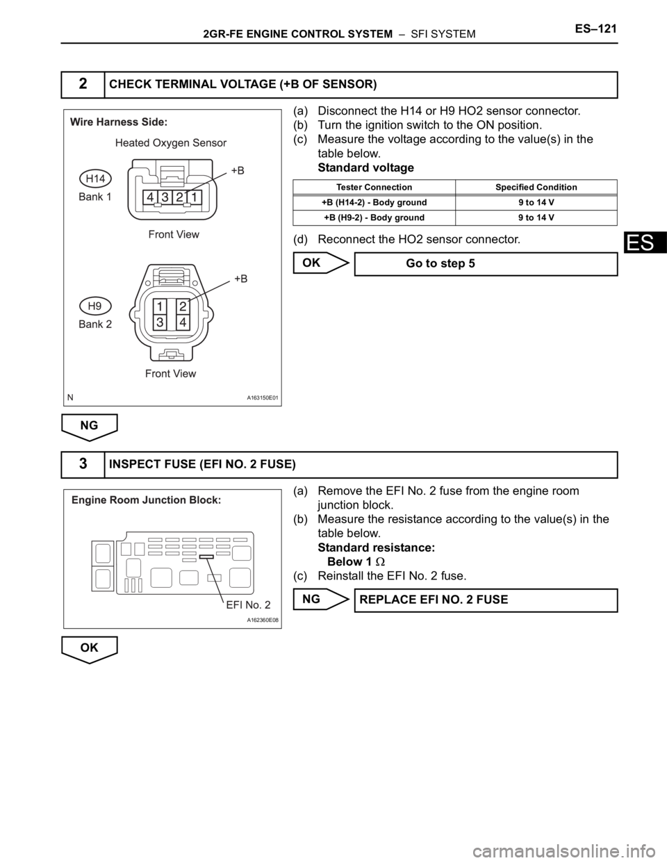
(a) Disconnect the H14 or H9 HO2 sensor connector.
(b) Turn the ignition switch to the ON position.
(c) Measure the voltage according to the value(s) in the
table below.
Standard voltage
(d) Reconnect the HO2 sensor connector.
OK
NG
(a) Remove the EFI No. 2 fuse from the engine room
junction block.
(b) Measure the resistance according to the value(s) in the
table below.
Standard resistance:
Below 1
(c) Reinstall the EFI No. 2 fuse.
NG
OK
2CHECK TERMINAL VOLTAGE (+B OF SENSOR)
A163150E01
Tester Connection Specified Condition
+B (H14-2) - Body ground 9 to 14 V
+B (H9-2) - Body ground 9 to 14 V
Go to step 5
3INSPECT FUSE (EFI NO. 2 FUSE)
A162360E08
REPLACE EFI NO. 2 FUSE
Page 434 of 3000
ES–1282GR-FE ENGINE CONTROL SYSTEM – SFI SYSTEM
ES
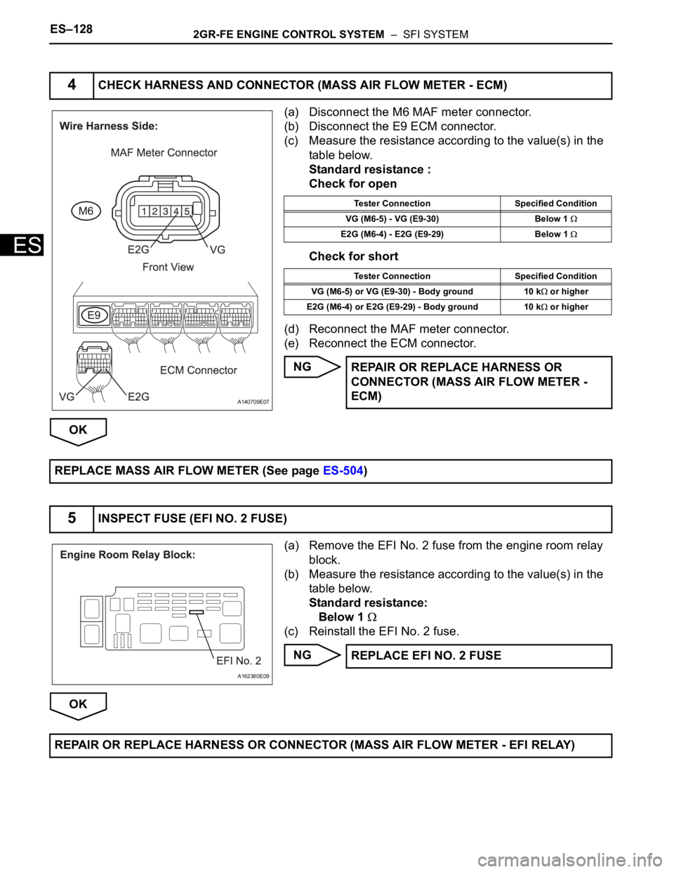
(a) Disconnect the M6 MAF meter connector.
(b) Disconnect the E9 ECM connector.
(c) Measure the resistance according to the value(s) in the
table below.
Standard resistance :
Check for open
Check for short
(d) Reconnect the MAF meter connector.
(e) Reconnect the ECM connector.
NG
OK
(a) Remove the EFI No. 2 fuse from the engine room relay
block.
(b) Measure the resistance according to the value(s) in the
table below.
Standard resistance:
Below 1
(c) Reinstall the EFI No. 2 fuse.
NG
OK
4CHECK HARNESS AND CONNECTOR (MASS AIR FLOW METER - ECM)
A140709E07
Tester Connection Specified Condition
VG (M6-5) - VG (E9-30) Below 1
E2G (M6-4) - E2G (E9-29) Below 1
Tester Connection Specified Condition
VG (M6-5) or VG (E9-30) - Body ground 10 k
or higher
E2G (M6-4) or E2G (E9-29) - Body ground 10 k
or higher
REPAIR OR REPLACE HARNESS OR
CONNECTOR (MASS AIR FLOW METER -
ECM)
REPLACE MASS AIR FLOW METER (See page ES-504)
5INSPECT FUSE (EFI NO. 2 FUSE)
A162360E09
REPLACE EFI NO. 2 FUSE
REPAIR OR REPLACE HARNESS OR CONNECTOR (MASS AIR FLOW METER - EFI RELAY)
Page 589 of 3000

ES–2962GR-FE ENGINE CONTROL SYSTEM – SFI SYSTEM
ES
DESCRIPTION
The stop light switch is a duplex system that transmits two signals: STP and ST1-. These two signals are
used by the ECM to monitor whether or not the brake system is working properly. If the signals, which
indicate the brake pedal is being depressed or released, are detected simultaneously, the ECM interprets
this as a malfunction in the stop light switch and sets the DTC.
HINT:
The normal conditions are as shown in the table below. The signals can be read using the intelligent
tester.
MONITOR DESCRIPTION
This DTC indicates that the stop light switch remains on. When the stop light switch remains ON during
"stop and go" driving, the ECM interprets this as a fault in the stop light switch and the MIL comes on and
the ECM stores the DTC. The vehicle must stop (less than 2 mph (3 km/h)) and go (19 mph (30 km/h) or
more) 5 times for two driving cycles in order to detect a malfunction.
MONITOR STRATEGY
TYPICAL ENABLING CONDITIONS
DTC P0504 Brake Switch "A" / "B" Correlation
DTC P0724 Brake Switch "B" Circuit High
Signals Brake Pedal Released In Transition Brake Pedal Depressed
STP OFF ON ON
ST1- ON ON OFF
DTC No. DTC Detection Condition Trouble Area
P0504Conditions (a), (b) and (c) continue for 0.5 seconds or
more (1 trip detection logic):
(a) Ignition switch in the ON position
(b) Brake pedal released
(c) STP signal OFF when ST1- signal OFF• Short in stop light switch signal circuit
• STOP fuse
• Stop light switch
•ECM
P0724The stop light switch remains ON even when the
vehicle is driven in a STOP (less than 2 mph (3 km/h))
and GO (19 mph (30 km/h) or more) fashion 5 times. (2
trip detection logic)• Short in stop light switch signal circuit
• Stop light switch
•ECM
Related DTCs P0724: Stop light switch/Rationality
Required sensors/Components Stop light switch, Vehicle speed sensor
Frequency of operation Continuous
Duration GO and STOP 5 times
MIL operation 2 driving cycles
Sequence of operation None
The monitor will run whenever this DTC is not present None
Ignition switch ON
Starter OFF
Battery voltage 8 V or more
GO (Vehicle speed is 18.65 mph (30 km/h) or more) Once
STOP (Vehicle speed is less than 1.86 mph (3 km/h)) Once
Page 609 of 3000
ES–3162GR-FE ENGINE CONTROL SYSTEM – SFI SYSTEM
ES
MONITOR DESCRIPTION
The battery supplies electricity to the ECM even when the ignition switch is off. This power allows the
ECM to store data such as DTC history, freeze frame data and fuel trim values. If the battery voltage falls
below a minimum level, these memories are cleared and the ECM determines that there is a malfunction
in the power supply circuit. When the engine is next started, the ECM illuminates the MIL and sets the
DTC.
HINT:
If DTC P0560 is set, the ECM does not store other DTCs.
MONITOR STRATEGY
TYPICAL ENABLING CONDITIONS
TYPICAL MALFUNCTION THRESHOLDS
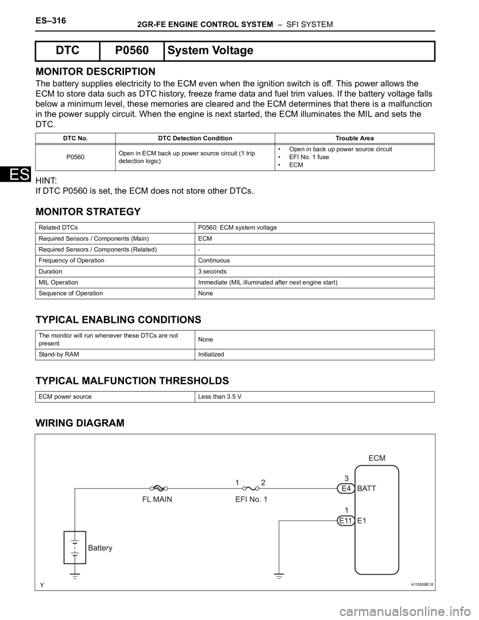
WIRING DIAGRAM
DTC P0560 System Voltage
DTC No. DTC Detection Condition Trouble Area
P0560Open in ECM back up power source circuit (1 trip
detection logic)• Open in back up power source circuit
• EFI No. 1 fuse
•ECM
Related DTCs P0560: ECM system voltage
Required Sensors / Components (Main) ECM
Required Sensors / Components (Related) -
Frequency of Operation Continuous
Duration 3 seconds
MIL Operation Immediate (MIL illuminated after next engine start)
Sequence of Operation None
The monitor will run whenever these DTCs are not
presentNone
Stand-by RAM Initialized
ECM power source Less than 3.5 V
A118508E18
Page 610 of 3000
2GR-FE ENGINE CONTROL SYSTEM – SFI SYSTEMES–317
ES
INSPECTION PROCEDURE
HINT:
Read freeze frame data using the intelligent tester. The ECM records vehicle and driving condition
information as freeze frame data the moment a DTC is stored. When troubleshooting, freeze frame data
can be helpful in determining whether the vehicle was running or stopped, whether the engine was
warmed up or not, whether the air-fuel ratio was lean or rich, as well as other data recorded at the time of
a malfunction.
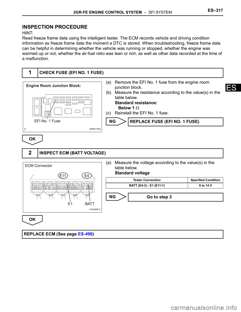
(a) Remove the EFI No. 1 fuse from the engine room
junction block.
(b) Measure the resistance according to the value(s) in the
table below.
Standard resistance:
Below 1
(c) Reinstall the EFI No. 1 fuse.
NG
OK
(a) Measure the voltage according to the value(s) in the
table below.
Standard voltage
NG
OK
1CHECK FUSE (EFI NO. 1 FUSE)
A080011E09
REPLACE FUSE (EFI NO. 1 FUSE)
2INSPECT ECM (BATT VOLTAGE)
A162489E13
Tester Connection Specified Condition
BATT (E4-3) - E1 (E11-1) 9 to 14 V
Go to step 3
REPLACE ECM (See page ES-498)