Page 783 of 3000
ENGINE HOOD / DOOR – BACK DOOR SUPPORTED–233
ED
DISPOSAL
HINT:
On the RH side, use the same procedures as on the LH side.
1. DISPOSE OF BACK DOOR STAY SUB-ASSEMBLY LH
(a) Horizontally fix the stay in a vise with the piston-rod
pulled out.
(b) Wearing safety glasses, gradually cut a part
between A and B as shown in the illustration using a
metal saw to gradually release the gas.
Dimensions
NOTICE:
Although the gas inside the damper stay is
colorless, odorless and harmless, there is a
possibility that metal debris from cutting could
enter the assembly. Therefore, cover it with
cloth or something similar.
B065104E10
ab
80 mm (3.15 in.) 20 mm (0.80 in.)
Page 842 of 3000

EXTERIOR – REAR DOOR WINDOW FRAME MOULDINGET–33
ET
INSTALLATION
1. INSTALL REAR DOOR WINDOW FRAME MOULDING
(a) Remove the tape from the rear door window frame
moulding.
(b) Clean the contact surface of the vehicle body with
white gasoline.
(c) Clean the outer circumference of the rear door
window frame moulding with white gasoline.
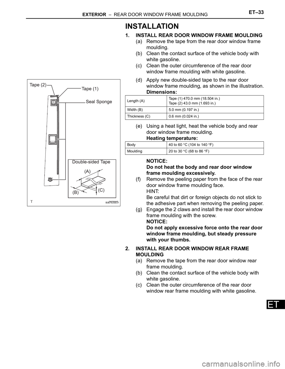
(d) Apply new double-sided tape to the rear door
window frame moulding, as shown in the illustration.
Dimensions:
(e) Using a heat light, heat the vehicle body and rear
door window frame moulding.
Heating temperature:
NOTICE:
Do not heat the body and rear door window
frame moulding excessively.
(f) Remove the peeling paper from the face of the rear
door window frame moulding face.
HINT:
Be careful that dirt or foreign objects do not stick to
the adhesive part when removing the peeling paper.
(g) Engage the 2 claws and install the rear door window
frame moulding with the screw.
NOTICE:
Do not apply excessive force onto the rear door
window frame moulding, but steady pressure
with your thumbs.
2. INSTALL REAR DOOR WINDOW REAR FRAME
MOULDING
(a) Remove the tape from the rear door window rear
frame moulding.
(b) Clean the contact surface of the vehicle body with
white gasoline.
(c) Clean the outer circumference of the rear door
window rear frame moulding with white gasoline.
B067635E01
Length (A)Tape (1) 470.0 mm (18.504 in.)
Tape (2) 43.0 mm (1.693 in.)
Width (B) 5.0 mm (0.197 in.)
Thickness (C) 0.6 mm (0.024 in.)
Body 40 to 60
C (104 to 140 F)
Moulding 20 to 30
C (68 to 86 F)
Page 843 of 3000

ET–34EXTERIOR – REAR DOOR WINDOW FRAME MOULDING
ET
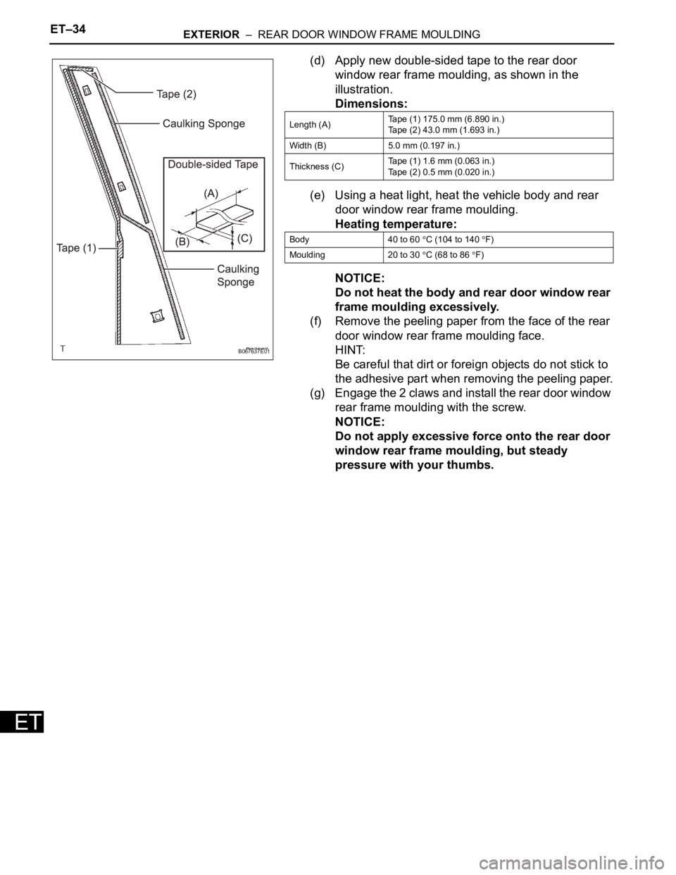
(d) Apply new double-sided tape to the rear door
window rear frame moulding, as shown in the
illustration.
Dimensions:
(e) Using a heat light, heat the vehicle body and rear
door window rear frame moulding.
Heating temperature:
NOTICE:
Do not heat the body and rear door window rear
frame moulding excessively.
(f) Remove the peeling paper from the face of the rear
door window rear frame moulding face.
HINT:
Be careful that dirt or foreign objects do not stick to
the adhesive part when removing the peeling paper.
(g) Engage the 2 claws and install the rear door window
rear frame moulding with the screw.
NOTICE:
Do not apply excessive force onto the rear door
window rear frame moulding, but steady
pressure with your thumbs.
B067637E01
Length (A)Tape (1) 175.0 mm (6.890 in.)
Tape (2) 43.0 mm (1.693 in.)
Width (B) 5.0 mm (0.197 in.)
Thickness (C)Tape (1) 1.6 mm (0.063 in.)
Tape (2) 0.5 mm (0.020 in.)
Body 40 to 60
C (104 to 140 F)
Moulding 20 to 30
C (68 to 86 F)
Page 2070 of 3000

PR–10PROPELLER SHAFT – PROPELLER SHAFT ASSEMBLY (for 4WD)
PR
(e) Tighten the 4 nuts.
Torque: 74 N*m (750 kgf*cm, 54 ft.*lbf)
2. FULLY TIGHTEN PROPELLER W/CENTER BEARING
SHAFT ASSEMBLY
(a) Remove the cloth from the joint.
(b) Using a hexagon wrench (6 mm), tighten the 6 bolts.
Torque: 29 N*m (296 kgf*cm, 21 ft.*lbf)
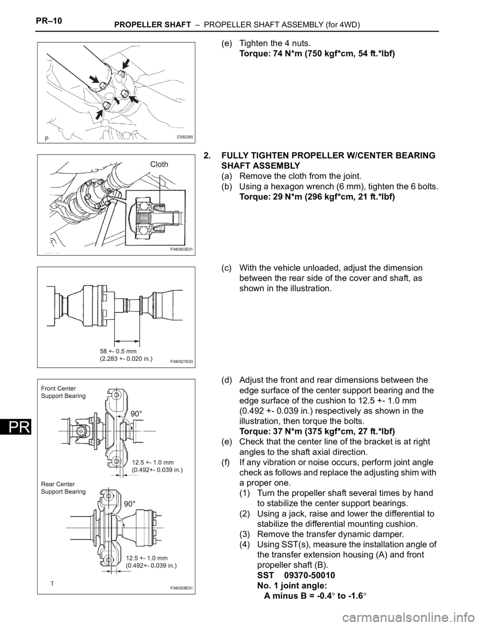
(c) With the vehicle unloaded, adjust the dimension
between the rear side of the cover and shaft, as
shown in the illustration.
(d) Adjust the front and rear dimensions between the
edge surface of the center support bearing and the
edge surface of the cushion to 12.5 +- 1.0 mm
(0.492 +- 0.039 in.) respectively as shown in the
illustration, then torque the bolts.
Torque: 37 N*m (375 kgf*cm, 27 ft.*lbf)
(e) Check that the center line of the bracket is at right
angles to the shaft axial direction.
(f) If any vibration or noise occurs, perform joint angle
check as follows and replace the adjusting shim with
a proper one.
(1) Turn the propeller shaft several times by hand
to stabilize the center support bearings.
(2) Using a jack, raise and lower the differential to
stabilize the differential mounting cushion.
(3) Remove the transfer dynamic damper.
(4) Using SST(s), measure the installation angle of
the transfer extension housing (A) and front
propeller shaft (B).
SST 09370-50010
No. 1 joint angle:
A minus B = -0.4
to -1.6
C092265
F040503E01
F040527E03
F040528E01