Page 25 of 3000

EM–262GR-FE ENGINE MECHANICAL – ENGINE ASSEMBLY
EM
REMOVAL
1. DISCHARGE FUEL SYSTEM PRESSURE (See page
FU-13)
2. DISCHARGE REFRIGERANT FROM
REFRIGERATION SYSTEM (See page AC-172)
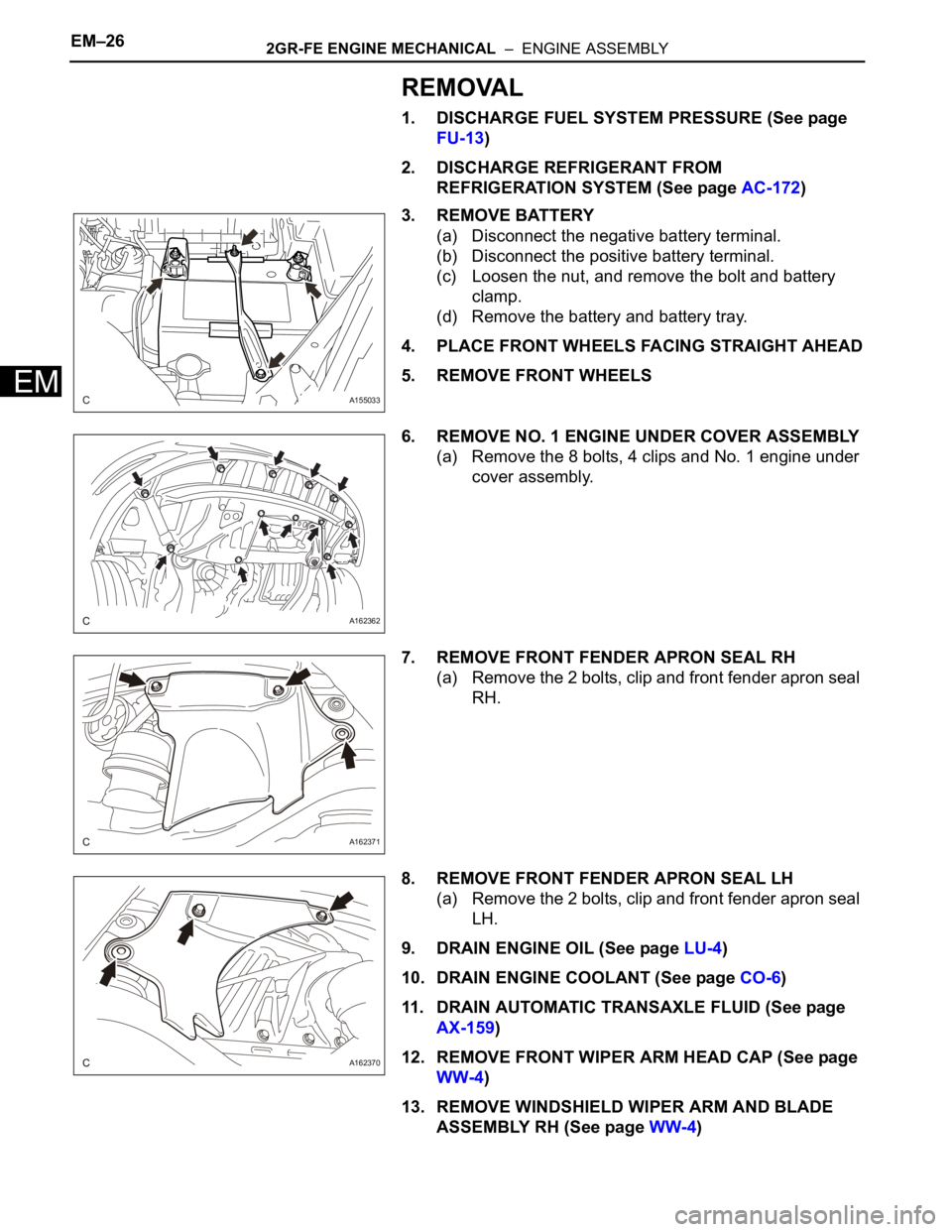
3. REMOVE BATTERY
(a) Disconnect the negative battery terminal.
(b) Disconnect the positive battery terminal.
(c) Loosen the nut, and remove the bolt and battery
clamp.
(d) Remove the battery and battery tray.
4. PLACE FRONT WHEELS FACING STRAIGHT AHEAD
5. REMOVE FRONT WHEELS
6. REMOVE NO. 1 ENGINE UNDER COVER ASSEMBLY
(a) Remove the 8 bolts, 4 clips and No. 1 engine under
cover assembly.
7. REMOVE FRONT FENDER APRON SEAL RH
(a) Remove the 2 bolts, clip and front fender apron seal
RH.
8. REMOVE FRONT FENDER APRON SEAL LH
(a) Remove the 2 bolts, clip and front fender apron seal
LH.
9. DRAIN ENGINE OIL (See page LU-4)
10. DRAIN ENGINE COOLANT (See page CO-6)
11. DRAIN AUTOMATIC TRANSAXLE FLUID (See page
AX-159)
12. REMOVE FRONT WIPER ARM HEAD CAP (See page
WW-4)
13. REMOVE WINDSHIELD WIPER ARM AND BLADE
ASSEMBLY RH (See page WW-4)
A155033
A162362
A162371
A162370
Page 92 of 3000
U151E AUTOMATIC TRANSAXLE – AUTOMATIC TRANSAXLE ASSEMBLYAX–165
AX
11. REMOVE OIL COOLER INLET TUBE NO.1
(a) Using SST and a wrench, disconnect the oil cooler
inlet tube No.1.
SST 09023-12701
12. REMOVE OIL COOLER OUTLET TUBE NO.1
(a) Using SST and a wrench, disconnect the oil cooler
outlet tube No.1.
SST 09023-12701
13. REMOVE ENGINE MOUNTING BRACKET FRONT
(a) Remove the 3 bolts and engine mounting bracket
front.
14. REMOVE AUTOMATIC TRANSAXLE ASSEMBLY
(a) Remove the 2 bolts and flywheel housing under
cover.
(b) Turn the crankshaft to gain access and remove the
6 bolts while holding the crankshaft pulley bolt with a
wrench.
HINT:
There will be one green colored bolt.
(c) Remove the 10 bolts.
(d) Separate and remove the automatic transaxle.
15. REMOVE TORQUE CONVERTER CLUTCH
ASSEMBLY
16. INSPECT TORQUE CONVERTER CLUTCH
ASSEMBLY
HINT:
(See page AX-170)
D030469E03
D030470
D030471
D030472
C163046
Page 94 of 3000

U151E AUTOMATIC TRANSAXLE – AUTOMATIC TRANSAXLE ASSEMBLYAX–167
AX
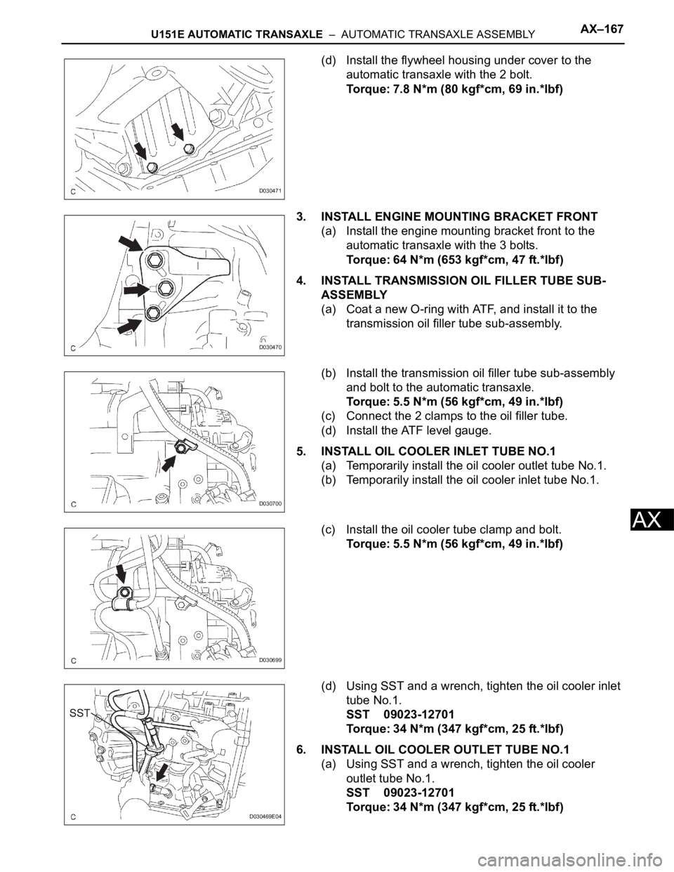
(d) Install the flywheel housing under cover to the
automatic transaxle with the 2 bolt.
Torque: 7.8 N*m (80 kgf*cm, 69 in.*lbf)
3. INSTALL ENGINE MOUNTING BRACKET FRONT
(a) Install the engine mounting bracket front to the
automatic transaxle with the 3 bolts.
Torque: 64 N*m (653 kgf*cm, 47 ft.*lbf)
4. INSTALL TRANSMISSION OIL FILLER TUBE SUB-
ASSEMBLY
(a) Coat a new O-ring with ATF, and install it to the
transmission oil filler tube sub-assembly.
(b) Install the transmission oil filler tube sub-assembly
and bolt to the automatic transaxle.
Torque: 5.5 N*m (56 kgf*cm, 49 in.*lbf)
(c) Connect the 2 clamps to the oil filler tube.
(d) Install the ATF level gauge.
5. INSTALL OIL COOLER INLET TUBE NO.1
(a) Temporarily install the oil cooler outlet tube No.1.
(b) Temporarily install the oil cooler inlet tube No.1.
(c) Install the oil cooler tube clamp and bolt.
Torque: 5.5 N*m (56 kgf*cm, 49 in.*lbf)
(d) Using SST and a wrench, tighten the oil cooler inlet
tube No.1.
SST 09023-12701
Torque: 34 N*m (347 kgf*cm, 25 ft.*lbf)
6. INSTALL OIL COOLER OUTLET TUBE NO.1
(a) Using SST and a wrench, tighten the oil cooler
outlet tube No.1.
SST 09023-12701
Torque: 34 N*m (347 kgf*cm, 25 ft.*lbf)
D030471
D030470
D030700
D030699
D030469E04
Page 101 of 3000
AX–166U151F AUTOMATIC TRANSAXLE – AUTOMATIC TRANSAXLE ASSEMBLY
AX
11. REMOVE OIL COOLER INLET TUBE NO.1
(a) Using SST and a wrench, disconnect the oil cooler
inlet tube No.1.
SST 09023-12701
12. REMOVE OIL COOLER OUTLET TUBE NO.1
(a) Using SST and a wrench, disconnect the oil cooler
outlet tube No.1.
SST 09023-12701
13. REMOVE ENGINE MOUNTING BRACKET FRONT
(a) Remove the 3 bolts and engine mounting bracket
front.
14. REMOVE TRANSFER STIFFENER PLATE RH
(a) Remove the 5 bolts and transfer stiffener plate RH.
15. REMOVE AUTOMATIC TRANSAXLE W/TRANSFER
(a) Remove the 2 bolts and flywheel housing under
cover.
(b) Turn the crankshaft to gain access and remove the
6 bolts while holding the crankshaft pulley bolt with a
wrench.
HINT:
There will be one green colored bolt.
D030469E03
D030470
D030512
D030471
D030472
Page 104 of 3000

U151F AUTOMATIC TRANSAXLE – AUTOMATIC TRANSAXLE ASSEMBLYAX–169
AX
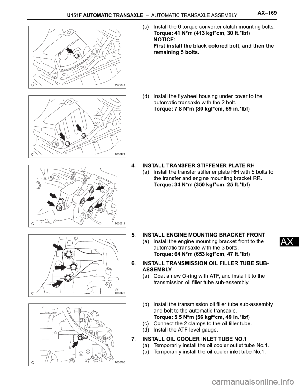
(c) Install the 6 torque converter clutch mounting bolts.
Torque: 41 N*m (413 kgf*cm, 30 ft.*lbf)
NOTICE:
First install the black colored bolt, and then the
remaining 5 bolts.
(d) Install the flywheel housing under cover to the
automatic transaxle with the 2 bolt.
Torque: 7.8 N*m (80 kgf*cm, 69 in.*lbf)
4. INSTALL TRANSFER STIFFENER PLATE RH
(a) Install the transfer stiffener plate RH with 5 bolts to
the transfer and engine mounting bracket RR.
Torque: 34 N*m (350 kgf*cm, 25 ft.*lbf)
5. INSTALL ENGINE MOUNTING BRACKET FRONT
(a) Install the engine mounting bracket front to the
automatic transaxle with the 3 bolts.
Torque: 64 N*m (653 kgf*cm, 47 ft.*lbf)
6. INSTALL TRANSMISSION OIL FILLER TUBE SUB-
ASSEMBLY
(a) Coat a new O-ring with ATF, and install it to the
transmission oil filler tube sub-assembly.
(b) Install the transmission oil filler tube sub-assembly
and bolt to the automatic transaxle.
Torque: 5.5 N*m (56 kgf*cm, 49 in.*lbf)
(c) Connect the 2 clamps to the oil filler tube.
(d) Install the ATF level gauge.
7. INSTALL OIL COOLER INLET TUBE NO.1
(a) Temporarily install the oil cooler outlet tube No.1.
(b) Temporarily install the oil cooler inlet tube No.1.
D030472
D030471
D030512
D030470
D030700
Page 163 of 3000
AH–6AXLE – FRONT AXLE HUB
AH
REMOVAL
HINT:
Replace the RH side using the same procedures as for the
LH side.
1. REMOVE FRONT WHEEL
2. REMOVE FRONT AXLE HUB LH NUT (See page DS-
5)
3. SEPARATE SPEED SENSOR FRONT LH (See page
DS-5)
4. SEPARATE FRONT DISC BRAKE CALIPER
ASSEMBLY LH
(a) Remove the 2 bolts and separate the front disc
brake caliper assembly LH from the steering
knuckle LH.
NOTICE:
Use a string or other device to keep the brake
caliper from hanging down.
5. REMOVE FRONT DISC
6. SEPARATE TIE ROD END SUB-ASSEMBLY LH (See
page DS-6)
7. SEPARATE FRONT SUSPENSION ARM SUB-
ASSEMBLY LOWER NO.1 LH (See page DS-6)
8. REMOVE FRONT AXLE ASSEMBLY LH
(a) Using a plastic hammer, separate the front drive
shaft assembly LH from the front axle hub sub-
assembly LH.
NOTICE:
Be careful not to damage the boot and ABS
speed sensor rotor.
(b) Remove the 2 bolts, nuts and steering knuckle LH
with the front axle nub sub-assembly LH.
C067088
D027403
C083023
Page 164 of 3000
AXLE – FRONT AXLE HUBAH–7
AH
DISASSEMBLY
1. REMOVE LOWER BALL JOINT ASSEMBLY FRONT
LH
(a) Remove the cotter pin and nut.
(b) Using SST(s), remove the lower ball joint assembly
front LH.
SST 09628-62011
2. REMOVE FRONT WHEEL BEARING DUST
DEFLECTOR NO.1 LH
(a) Using a screwdriver, remove the bearing dust
deflector NO. 1 LH.
3. REMOVE FRONT AXLE HUB LH HOLE SNAP RING
(a) Using snap ring pliers, remove the front axle hub LH
hole snap ring.
4. REMOVE FRONT AXLE ASSEMBLY LH
(a) Using SST(s), remove the front axle hub sub-
assembly LH.
SST 09520-00031
(b) Using SST(s) and a press, remove the bearing inner
race (outside) from the front axle hub sub-assembly
LH.
SST 09950-00020, 09950-60010 (09951-00430),
09950-70010 (09951-07100)
5. REMOVE DISC BRAKE DUST COVER FRONT LH
(a) Using a torx wrench (T30), remove the 4 bolts and
disc brake dust cover front LH.
HINT:
Torx is a registered trademark of Textron Inc.
F040153E02
F040154
F045465
F040156E05
F002261E03
Page 166 of 3000

AXLE – FRONT AXLE HUBAH–9
AH
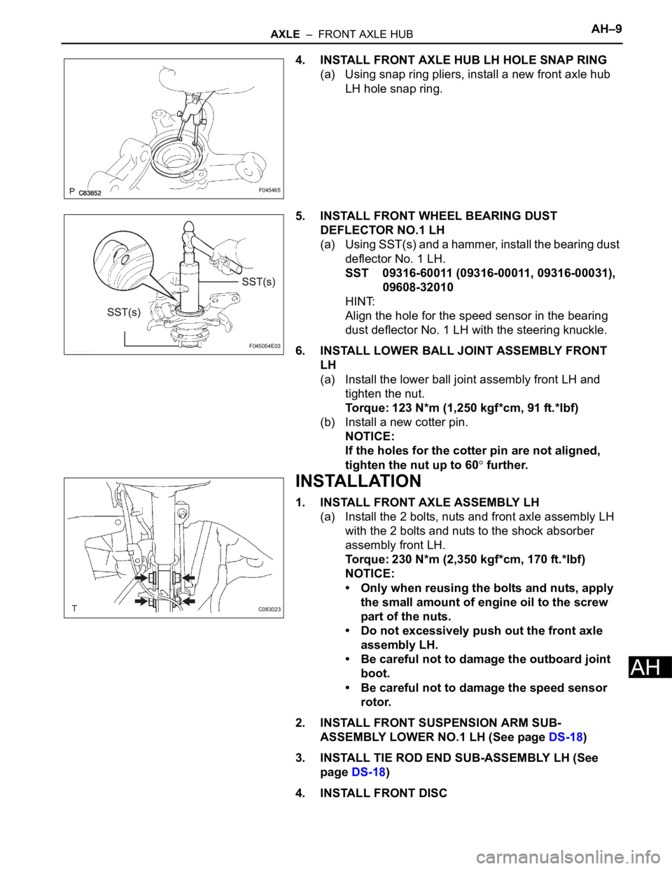
4. INSTALL FRONT AXLE HUB LH HOLE SNAP RING
(a) Using snap ring pliers, install a new front axle hub
LH hole snap ring.
5. INSTALL FRONT WHEEL BEARING DUST
DEFLECTOR NO.1 LH
(a) Using SST(s) and a hammer, install the bearing dust
deflector No. 1 LH.
SST 09316-60011 (09316-00011, 09316-00031),
09608-32010
HINT:
Align the hole for the speed sensor in the bearing
dust deflector No. 1 LH with the steering knuckle.
6. INSTALL LOWER BALL JOINT ASSEMBLY FRONT
LH
(a) Install the lower ball joint assembly front LH and
tighten the nut.
Torque: 123 N*m (1,250 kgf*cm, 91 ft.*lbf)
(b) Install a new cotter pin.
NOTICE:
If the holes for the cotter pin are not aligned,
tighten the nut up to 60
further.
INSTALLATION
1. INSTALL FRONT AXLE ASSEMBLY LH
(a) Install the 2 bolts, nuts and front axle assembly LH
with the 2 bolts and nuts to the shock absorber
assembly front LH.
Torque: 230 N*m (2,350 kgf*cm, 170 ft.*lbf)
NOTICE:
• Only when reusing the bolts and nuts, apply
the small amount of engine oil to the screw
part of the nuts.
• Do not excessively push out the front axle
assembly LH.
• Be careful not to damage the outboard joint
boot.
• Be careful not to damage the speed sensor
rotor.
2. INSTALL FRONT SUSPENSION ARM SUB-
ASSEMBLY LOWER NO.1 LH (See page DS-18)
3. INSTALL TIE ROD END SUB-ASSEMBLY LH (See
page DS-18)
4. INSTALL FRONT DISC
F045465
F045054E03
C083023