2007 TOYOTA SIENNA battery location
[x] Cancel search: battery locationPage 341 of 3000

2GR-FE ENGINE CONTROL SYSTEM – SFI SYSTEMES–15
ES
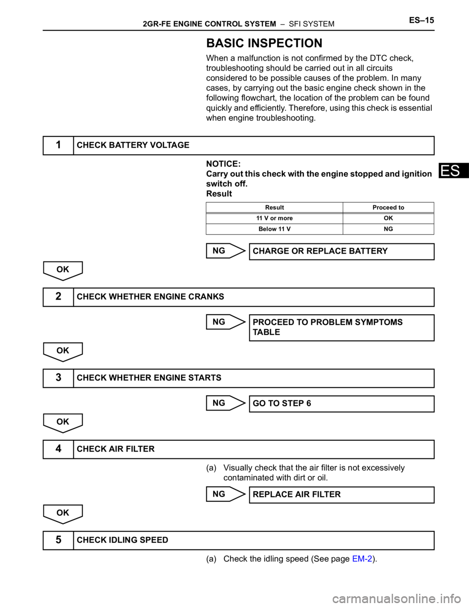
BASIC INSPECTION
When a malfunction is not confirmed by the DTC check,
troubleshooting should be carried out in all circuits
considered to be possible causes of the problem. In many
cases, by carrying out the basic engine check shown in the
following flowchart, the location of the problem can be found
quickly and efficiently. Therefore, using this check is essential
when engine troubleshooting.
NOTICE:
Carry out this check with the engine stopped and ignition
switch off.
Result
NG
OK
NG
OK
NG
OK
(a) Visually check that the air filter is not excessively
contaminated with dirt or oil.
NG
OK
(a) Check the idling speed (See page EM-2).
1CHECK BATTERY VOLTAGE
Result Proceed to
11 V or more OK
Below 11 V NG
CHARGE OR REPLACE BATTERY
2CHECK WHETHER ENGINE CRANKS
PROCEED TO PROBLEM SYMPTOMS
TA B L E
3CHECK WHETHER ENGINE STARTS
GO TO STEP 6
4CHECK AIR FILTER
REPLACE AIR FILTER
5CHECK IDLING SPEED
Page 361 of 3000

2GR-FE ENGINE CONTROL SYSTEM – SFI SYSTEMES–43
ES
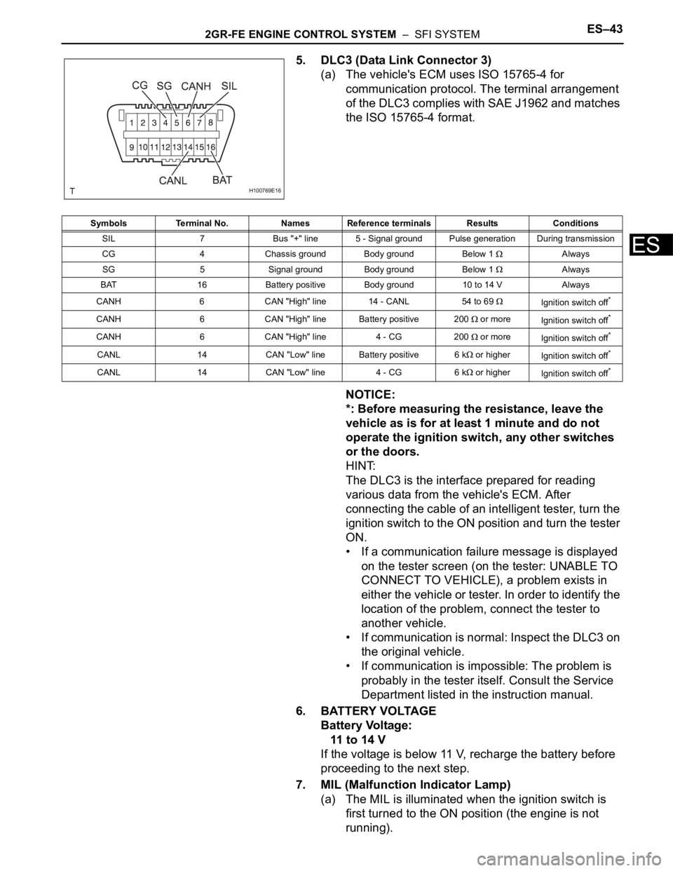
5. DLC3 (Data Link Connector 3)
(a) The vehicle's ECM uses ISO 15765-4 for
communication protocol. The terminal arrangement
of the DLC3 complies with SAE J1962 and matches
the ISO 15765-4 format.
NOTICE:
*: Before measuring the resistance, leave the
vehicle as is for at least 1 minute and do not
operate the ignition switch, any other switches
or the doors.
HINT:
The DLC3 is the interface prepared for reading
various data from the vehicle's ECM. After
connecting the cable of an intelligent tester, turn the
ignition switch to the ON position and turn the tester
ON.
• If a communication failure message is displayed
on the tester screen (on the tester: UNABLE TO
CONNECT TO VEHICLE), a problem exists in
either the vehicle or tester. In order to identify the
location of the problem, connect the tester to
another vehicle.
• If communication is normal: Inspect the DLC3 on
the original vehicle.
• If communication is impossible: The problem is
probably in the tester itself. Consult the Service
Department listed in the instruction manual.
6. BATTERY VOLTAGE
Battery Voltage:
11 to 14 V
If the voltage is below 11 V, recharge the battery before
proceeding to the next step.
7. MIL (Malfunction Indicator Lamp)
(a) The MIL is illuminated when the ignition switch is
first turned to the ON position (the engine is not
running).
H100769E16
Symbols Terminal No. Names Reference terminals Results Conditions
SIL 7 Bus "+" line 5 - Signal ground Pulse generation During transmission
CG 4 Chassis ground Body ground Below 1
Always
SG 5 Signal ground Body ground Below 1
Always
BAT 16 Battery positive Body ground 10 to 14 V Always
CANH 6 CAN "High" line 14 - CANL 54 to 69
Ignition switch off*
CANH 6 CAN "High" line Battery positive 200 or more
Ignition switch off*
CANH 6 CAN "High" line 4 - CG 200 or more
Ignition switch off*
CANL 14 CAN "Low" line Battery positive 6 k or higher
Ignition switch off*
CANL 14 CAN "Low" line 4 - CG 6 k or higher
Ignition switch off*
Page 777 of 3000

2GR-FE ENGINE CONTROL SYSTEM – SFI SYSTEMES–15
ES
BASIC INSPECTION
When a malfunction is not confirmed by the DTC check,
troubleshooting should be carried out in all circuits
considered to be possible causes of the problem. In many
cases, by carrying out the basic engine check shown in the
following flowchart, the location of the problem can be found
quickly and efficiently. Therefore, using this check is essential
when engine troubleshooting.
NOTICE:
Carry out this check with the engine stopped and ignition
switch off.
Result
NG
OK
NG
OK
NG
OK
(a) Visually check that the air filter is not excessively
contaminated with dirt or oil.
NG
OK
(a) Check the idling speed (See page EM-2).
1CHECK BATTERY VOLTAGE
Result Proceed to
11 V or more OK
Below 11 V NG
CHARGE OR REPLACE BATTERY
2CHECK WHETHER ENGINE CRANKS
PROCEED TO PROBLEM SYMPTOMS
TA B L E
3CHECK WHETHER ENGINE STARTS
GO TO STEP 6
4CHECK AIR FILTER
REPLACE AIR FILTER
5CHECK IDLING SPEED
Page 813 of 3000

2GR-FE ENGINE CONTROL SYSTEM – SFI SYSTEMES–33
ES
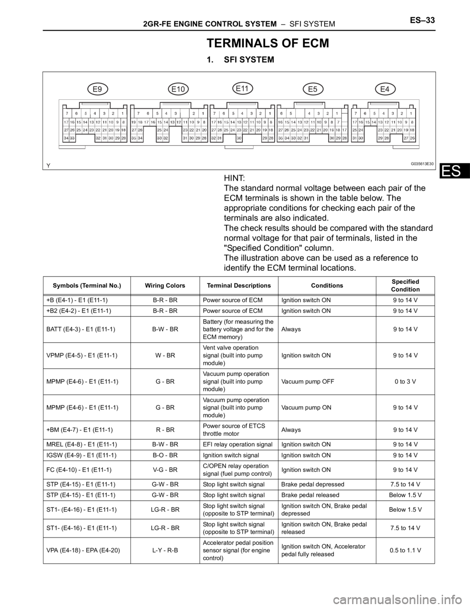
TERMINALS OF ECM
1. SFI SYSTEM
HINT:
The standard normal voltage between each pair of the
ECM terminals is shown in the table below. The
appropriate conditions for checking each pair of the
terminals are also indicated.
The check results should be compared with the standard
normal voltage for that pair of terminals, listed in the
"Specified Condition" column.
The illustration above can be used as a reference to
identify the ECM terminal locations.
G035613E30
Symbols (Terminal No.) Wiring Colors Terminal Descriptions ConditionsSpecified
Condition
+B (E4-1) - E1 (E11-1) B-R - BR Power source of ECM Ignition switch ON 9 to 14 V
+B2 (E4-2) - E1 (E11-1) B-R - BR Power source of ECM Ignition switch ON 9 to 14 V
BATT (E4-3) - E1 (E11-1) B-W - BRBattery (for measuring the
battery voltage and for the
ECM memory)Always 9 to 14 V
VPMP (E4-5) - E1 (E11-1) W - BRVent valve operation
signal (built into pump
module)Ignition switch ON 9 to 14 V
MPMP (E4-6) - E1 (E11-1) G - BRVacuum pump operation
signal (built into pump
module)Vacuum pump OFF 0 to 3 V
MPMP (E4-6) - E1 (E11-1) G - BRVacuum pump operation
signal (built into pump
module)Vacuum pump ON 9 to 14 V
+BM (E4-7) - E1 (E11-1) R - BRPower source of ETCS
throttle motorAlways 9 to 14 V
MREL (E4-8) - E1 (E11-1) B-W - BR EFI relay operation signal Ignition switch ON 9 to 14 V
IGSW (E4-9) - E1 (E11-1) B-O - BRIgnition switch signal Ignition switch ON 9 to 14 V
FC (E4-10) - E1 (E11-1) V-G - BRC/OPEN relay operation
signal (fuel pump control)Ignition switch ON 9 to 14 V
STP (E4-15) - E1 (E11-1) G-W - BR Stop light switch signal Brake pedal depressed 7.5 to 14 V
STP (E4-15) - E1 (E11-1) G-W - BR Stop light switch signal Brake pedal released Below 1.5 V
ST1- (E4-16) - E1 (E11-1) LG-R - BRStop light switch signal
(opposite to STP terminal)Ignition switch ON, Brake pedal
depressedBelow 1.5 V
ST1- (E4-16) - E1 (E11-1) LG-R - BRStop light switch signal
(opposite to STP terminal)Ignition switch ON, Brake pedal
released7.5 to 14 V
VPA (E4-18) - EPA (E4-20) L-Y - R-BAccelerator pedal position
sensor signal (for engine
control)Ignition switch ON, Accelerator
pedal fully released0.5 to 1.1 V
Page 825 of 3000

2GR-FE ENGINE CONTROL SYSTEM – SFI SYSTEMES–43
ES
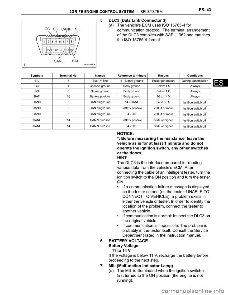
5. DLC3 (Data Link Connector 3)
(a) The vehicle's ECM uses ISO 15765-4 for
communication protocol. The terminal arrangement
of the DLC3 complies with SAE J1962 and matches
the ISO 15765-4 format.
NOTICE:
*: Before measuring the resistance, leave the
vehicle as is for at least 1 minute and do not
operate the ignition switch, any other switches
or the doors.
HINT:
The DLC3 is the interface prepared for reading
various data from the vehicle's ECM. After
connecting the cable of an intelligent tester, turn the
ignition switch to the ON position and turn the tester
ON.
• If a communication failure message is displayed
on the tester screen (on the tester: UNABLE TO
CONNECT TO VEHICLE), a problem exists in
either the vehicle or tester. In order to identify the
location of the problem, connect the tester to
another vehicle.
• If communication is normal: Inspect the DLC3 on
the original vehicle.
• If communication is impossible: The problem is
probably in the tester itself. Consult the Service
Department listed in the instruction manual.
6. BATTERY VOLTAGE
Battery Voltage:
11 to 14 V
If the voltage is below 11 V, recharge the battery before
proceeding to the next step.
7. MIL (Malfunction Indicator Lamp)
(a) The MIL is illuminated when the ignition switch is
first turned to the ON position (the engine is not
running).
H100769E16
Symbols Terminal No. Names Reference terminals Results Conditions
SIL 7 Bus "+" line 5 - Signal ground Pulse generation During transmission
CG 4 Chassis ground Body ground Below 1
Always
SG 5 Signal ground Body ground Below 1
Always
BAT 16 Battery positive Body ground 10 to 14 V Always
CANH 6 CAN "High" line 14 - CANL 54 to 69
Ignition switch off*
CANH 6 CAN "High" line Battery positive 200 or more
Ignition switch off*
CANH 6 CAN "High" line 4 - CG 200 or more
Ignition switch off*
CANL 14 CAN "Low" line Battery positive 6 k or higher
Ignition switch off*
CANL 14 CAN "Low" line 4 - CG 6 k or higher
Ignition switch off*