Page 81 of 3000

2GR-FE IGNITION – IGNITION COIL AND SPARK PLUGIG–7
IG
(3) Check the spark plug (See page EM-1).
Result
(4) Check the power supply to the ignition coil.
1. Turn the ignition switch to the ON position.
2. Check that there is battery voltage at the
ignition coil positive (+) terminal.
Result
(5) Measure the resistance of the crankshaft
position sensor (See page ES-514).
Result
(6) Check the IGT signal from the ECM (See page
ES-233)
Result
(e) Using a 16 mm (0.63 in.) plug wrench, install the
spark plugs.
Torque: 18 N*m (184 kgf*cm, 13 ft.*lbf)
(f) Connect the 6 fuel injector connectors.
(g) Install the ignition coil assembly (See page IG-10).
2. INSPECT SPARK PLUG
NOTICE:
• Never use a wire brush for cleaning.
• Never attempt to adjust the electrode gap on a
used spark plug.
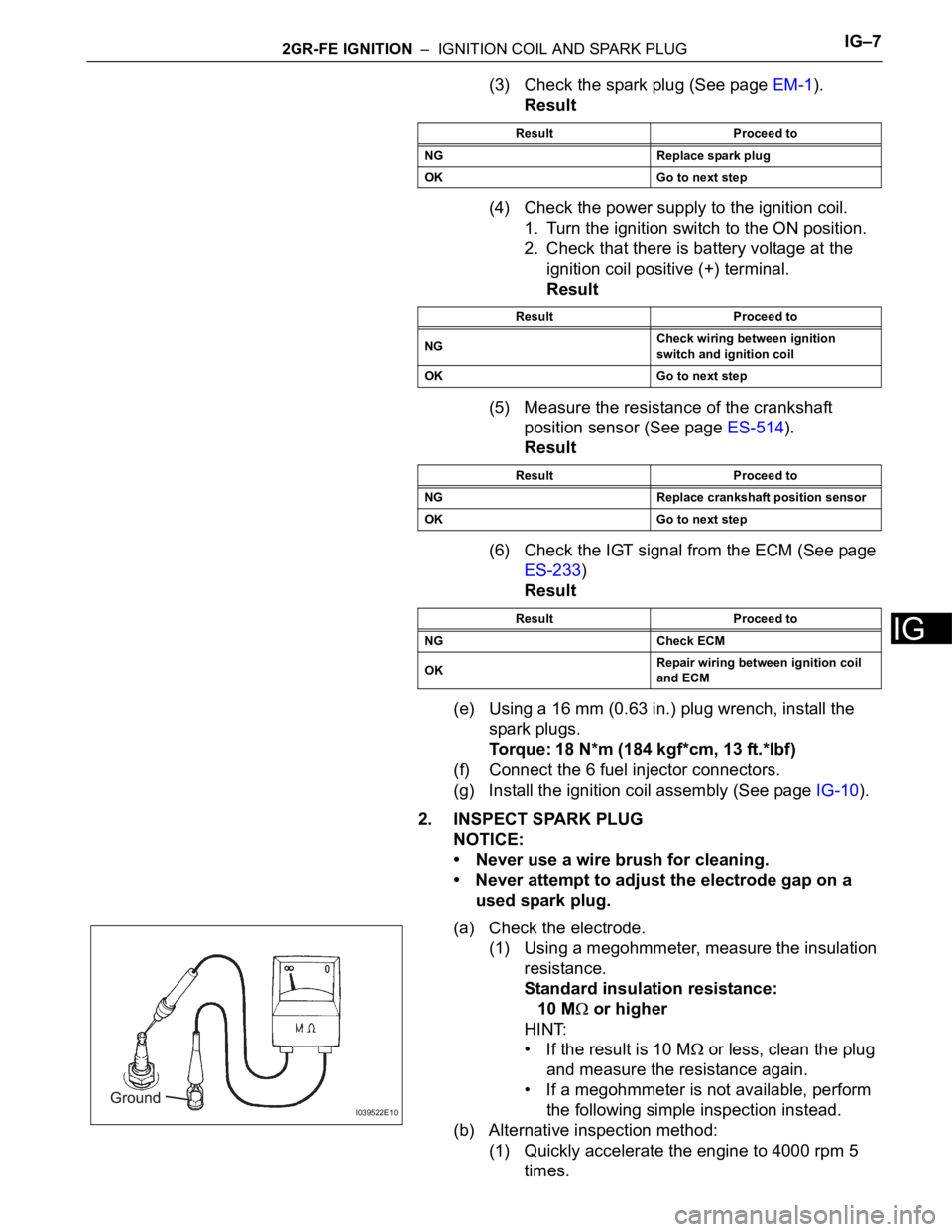
(a) Check the electrode.
(1) Using a megohmmeter, measure the insulation
resistance.
Standard insulation resistance:
10 M
or higher
HINT:
• If the result is 10 M
or less, clean the plug
and measure the resistance again.
• If a megohmmeter is not available, perform
the following simple inspection instead.
(b) Alternative inspection method:
(1) Quickly accelerate the engine to 4000 rpm 5
times.
Result Proceed to
NG Replace spark plug
OK Go to next step
Result Proceed to
NGCheck wiring between ignition
switch and ignition coil
OK Go to next step
Result Proceed to
NG Replace crankshaft position sensor
OK Go to next step
Result Proceed to
NG Check ECM
OKRepair wiring between ignition coil
and ECM
I039522E10
Page 547 of 3000

2GR-FE ENGINE CONTROL SYSTEM – SFI SYSTEMES–241
ES
HINT:
• These DTCs indicate malfunctions relating to the primary circuit.
• If DTC P0351 is set, check the No. 1 ignition coil with igniter circuit.
• If DTC P0352 is set, check the No. 2 ignition coil with igniter circuit.
• If DTC P0353 is set, check the No. 3 ignition coil with igniter circuit.
• If DTC P0354 is set, check the No. 4 ignition coil with igniter circuit.
• If DTC P0355 is set, check the No. 5 ignition coil with igniter circuit.
• If DTC P0356 is set, check the No. 6 ignition coil with igniter circuit.
DESCRIPTION
A Direct Ignition System (DIS) is used on this vehicle.
The DIS is a 1-cylinder ignition system in which each cylinder is ignited by one ignition coil and one spark
plug is connected to the end of each secondary wiring. High-voltage is generated in the secondary wiring
and then applied directly to each spark plug. The sparks of the spark plugs pass from the center
electrodes to the ground electrodes.
The ECM determines the ignition timing and transmits the ignition (IGT) signals to each cylinder. Using the
IGT signal, the ECM turns the power transistor inside the igniter on and off. The power transistor, in turn,
switches on and off the current to the primary coil. When the current to the primary coil is cut off, high-
voltage is generated in the secondary coil. This voltage is applied to the spark plugs, causing them to
spark inside the cylinders. As the ECM cuts the current to the primary coil off, the igniter sends back an
ignition confirmation (IGF) signal to the ECM, for each cylinder ignition.
DTC P0351 Ignition Coil "A" Primary / Secondary Circuit
DTC P0352 Ignition Coil "B" Primary / Secondary Circuit
DTC P0353 Ignition Coil "C" Primary / Secondary Circuit
DTC P0354 Ignition Coil "D" Primary / Secondary Circuit
DTC P0355 Ignition Coil "E" Primary / Secondary Circuit
DTC P0356 Ignition Coil "F" Primary / Secondary Circuit
Page 819 of 3000

2GR-FE ENGINE CONTROL SYSTEM – SFI SYSTEMES–39
ES
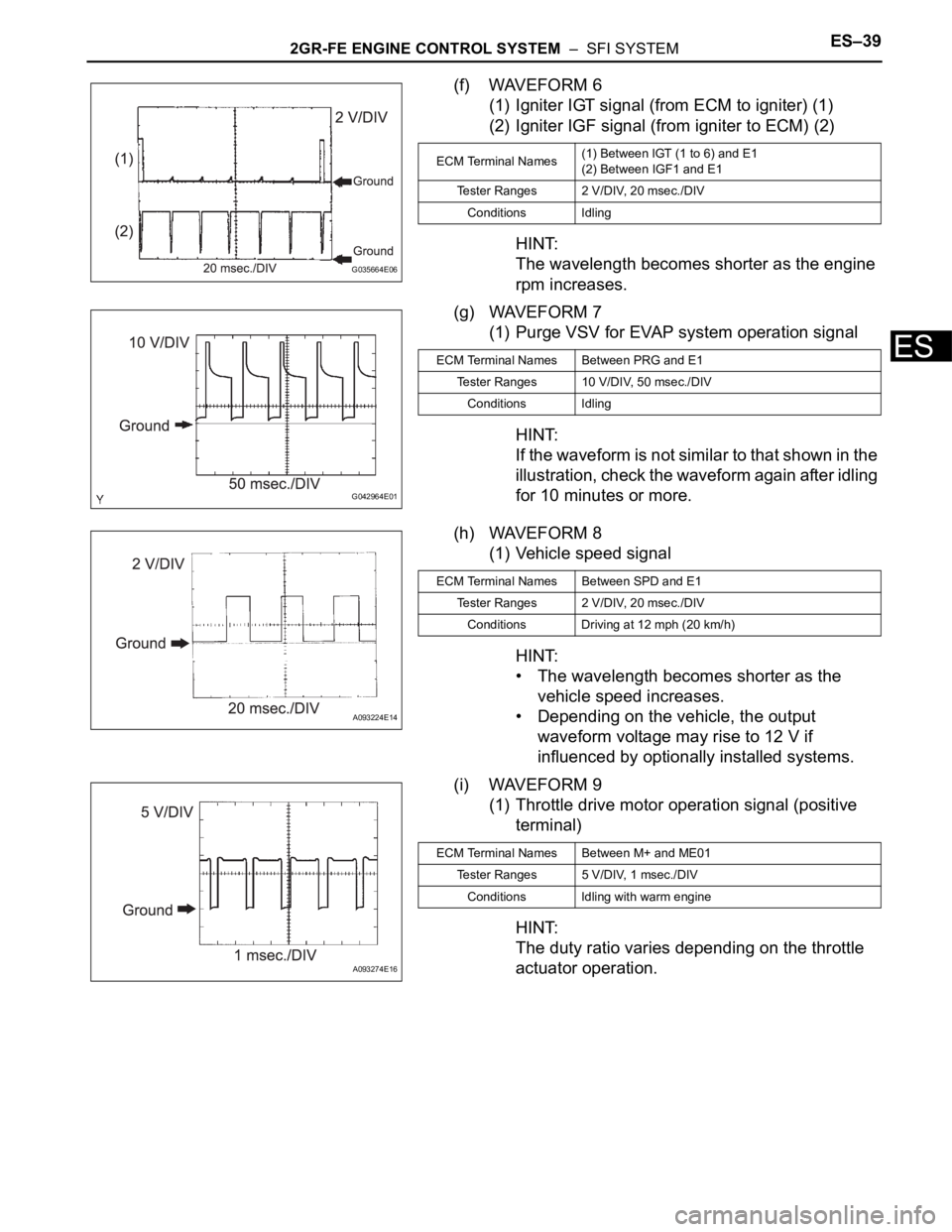
(f) WAVEFORM 6
(1) Igniter IGT signal (from ECM to igniter) (1)
(2) Igniter IGF signal (from igniter to ECM) (2)
HINT:
The wavelength becomes shorter as the engine
rpm increases.
(g) WAVEFORM 7
(1) Purge VSV for EVAP system operation signal
HINT:
If the waveform is not similar to that shown in the
illustration, check the waveform again after idling
for 10 minutes or more.
(h) WAVEFORM 8
(1) Vehicle speed signal
HINT:
• The wavelength becomes shorter as the
vehicle speed increases.
• Depending on the vehicle, the output
waveform voltage may rise to 12 V if
influenced by optionally installed systems.
(i) WAVEFORM 9
(1) Throttle drive motor operation signal (positive
terminal)
HINT:
The duty ratio varies depending on the throttle
actuator operation.
G035664E06
ECM Terminal Names(1) Between IGT (1 to 6) and E1
(2) Between IGF1 and E1
Tester Ranges 2 V/DIV, 20 msec./DIV
Conditions Idling
G042964E01
ECM Terminal Names Between PRG and E1
Tester Ranges 10 V/DIV, 50 msec./DIV
Conditions Idling
A093224E14
ECM Terminal Names Between SPD and E1
Tester Ranges 2 V/DIV, 20 msec./DIV
Conditions Driving at 12 mph (20 km/h)
A093274E16
ECM Terminal Names Between M+ and ME01
Tester Ranges 5 V/DIV, 1 msec./DIV
Conditions Idling with warm engine
Page 1316 of 3000

2GR-FE IGNITION – IGNITION COIL AND SPARK PLUGIG–7
IG
(3) Check the spark plug (See page EM-1).
Result
(4) Check the power supply to the ignition coil.
1. Turn the ignition switch to the ON position.
2. Check that there is battery voltage at the
ignition coil positive (+) terminal.
Result
(5) Measure the resistance of the crankshaft
position sensor (See page ES-514).
Result
(6) Check the IGT signal from the ECM (See page
ES-233)
Result
(e) Using a 16 mm (0.63 in.) plug wrench, install the
spark plugs.
Torque: 18 N*m (184 kgf*cm, 13 ft.*lbf)
(f) Connect the 6 fuel injector connectors.
(g) Install the ignition coil assembly (See page IG-10).
2. INSPECT SPARK PLUG
NOTICE:
• Never use a wire brush for cleaning.
• Never attempt to adjust the electrode gap on a
used spark plug.
(a) Check the electrode.
(1) Using a megohmmeter, measure the insulation
resistance.
Standard insulation resistance:
10 M
or higher
HINT:
• If the result is 10 M
or less, clean the plug
and measure the resistance again.
• If a megohmmeter is not available, perform
the following simple inspection instead.
(b) Alternative inspection method:
(1) Quickly accelerate the engine to 4000 rpm 5
times.
Result Proceed to
NG Replace spark plug
OK Go to next step
Result Proceed to
NGCheck wiring between ignition
switch and ignition coil
OK Go to next step
Result Proceed to
NG Replace crankshaft position sensor
OK Go to next step
Result Proceed to
NG Check ECM
OKRepair wiring between ignition coil
and ECM
I039522E10