2007 TOYOTA SIENNA diagnostic menu
[x] Cancel search: diagnostic menuPage 352 of 3000

ES–262GR-FE ENGINE CONTROL SYSTEM – SFI SYSTEM
ES
READINESS MONITOR DRIVE
PAT T E R N
1. PURPOSE OF READINESS TESTS
• The On-Board Diagnostic (OBD II) system is
designed to monitor the performance of emission-
related components, and indicate any detected
abnormalities with DTCs (Diagnostic Trouble Codes).
Since various components need to be monitored in
different driving conditions, the OBD II system is
designed to run separate monitoring programs called
Readiness Monitors.
• The intelligent tester's software must be version 9.0 or
newer to view the Readiness Monitor status. To view
the status, select the following menu items:
DIAGNOSIS / ENHANCED OBD II / MONITOR INFO
/ MONITOR STATUS.
• When the Readiness Monitor status reads COMPL
(complete), the necessary conditions have been met
for running the performance tests for that Readiness
Monitor.
• A generic OBD II scan tool can also be used to view
the Readiness Monitor status.
HINT:
Many Inspection and Maintenance (I/M) programs
require a vehicle's Readiness Monitor status to show
COMPL before beginning emission tests.
The Readiness Monitor will be reset to INCMPL
(incomplete) if:
• The ECM has lost battery power or broken a fuse.
• DTCs have been cleared.
• The conditions for running the Readiness Monitor
have not been met.
If the Readiness Monitor status shows INCMPL, follow
the appropriate Readiness Monitor Drive Pattern to
change the status to COMPL.
CAUTION:
Strictly observe posted speed limits, traffic laws, and
road conditions when performing these drive
patterns.
NOTICE:
These drive patterns represent the fastest method of
satisfying all conditions necessary to achieve
complete status for each specific Readiness
Monitor.
In the event of a drive pattern being interrupted
(possibly due to factors such as traffic conditions),
the drive pattern can be resumed. In most cases, the
Readiness Monitor will still achieve complete status
upon completion of the drive pattern.
To ensure completion of the Readiness Monitors,
avoid sudden changes in vehicle load and speed
(driving up and down hills and/or sudden
acceleration).
Page 482 of 3000

ES–1762GR-FE ENGINE CONTROL SYSTEM – SFI SYSTEM
ES
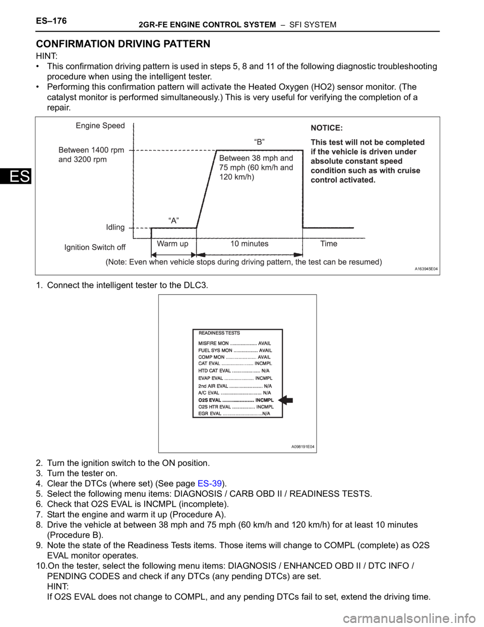
CONFIRMATION DRIVING PATTERN
HINT:
• This confirmation driving pattern is used in steps 5, 8 and 11 of the following diagnostic troubleshooting
procedure when using the intelligent tester.
• Performing this confirmation pattern will activate the Heated Oxygen (HO2) sensor monitor. (The
catalyst monitor is performed simultaneously.) This is very useful for verifying the completion of a
repair.
1. Connect the intelligent tester to the DLC3.
2. Turn the ignition switch to the ON position.
3. Turn the tester on.
4. Clear the DTCs (where set) (See page ES-39).
5. Select the following menu items: DIAGNOSIS / CARB OBD II / READINESS TESTS.
6. Check that O2S EVAL is INCMPL (incomplete).
7. Start the engine and warm it up (Procedure A).
8. Drive the vehicle at between 38 mph and 75 mph (60 km/h and 120 km/h) for at least 10 minutes
(Procedure B).
9. Note the state of the Readiness Tests items. Those items will change to COMPL (complete) as O2S
EVAL monitor operates.
10.On the tester, select the following menu items: DIAGNOSIS / ENHANCED OBD II / DTC INFO /
PENDING CODES and check if any DTCs (any pending DTCs) are set.
HINT:
If O2S EVAL does not change to COMPL, and any pending DTCs fail to set, extend the driving time.
A163945E04
A098191E04
Page 537 of 3000

2GR-FE ENGINE CONTROL SYSTEM – SFI SYSTEMES–231
ES
INSPECTION PROCEDURE
HINT:
• If no problem is found by this diagnostic troubleshooting procedure, troubleshoot the engine
mechanical systems.
• Check the engine speed. The engine speed can be checked by using the intelligent tester. Perform the
following procedure:
(a) Connect the intelligent tester to the DLC3.
(b) Start the engine.
(c) Turn the tester on.
(d) Select the following menu items: DIAGNOSIS / ENHANCED OBD II / DATA LIST / PRIMARY /
ENGINE SPD.
The engine speed may be indicated as zero despite the engine revolving normally. This is caused
by a lack of NE signals from the Crankshaft Position (CKP) sensor. Alternatively, the engine speed
may be indicated as lower than the actual engine speed, if the CKP sensor voltage output is
insufficient.
• Read freeze frame data using the intelligent tester. The ECM records vehicle and driving condition
information as freeze frame data the moment a DTC is stored. When troubleshooting, freeze frame
data can be helpful in determining whether the vehicle was running or stopped, whether the engine
was warmed up or not, whether the air-fuel ratio was lean or rich, as well as other data recorded at the
time of a malfunction.
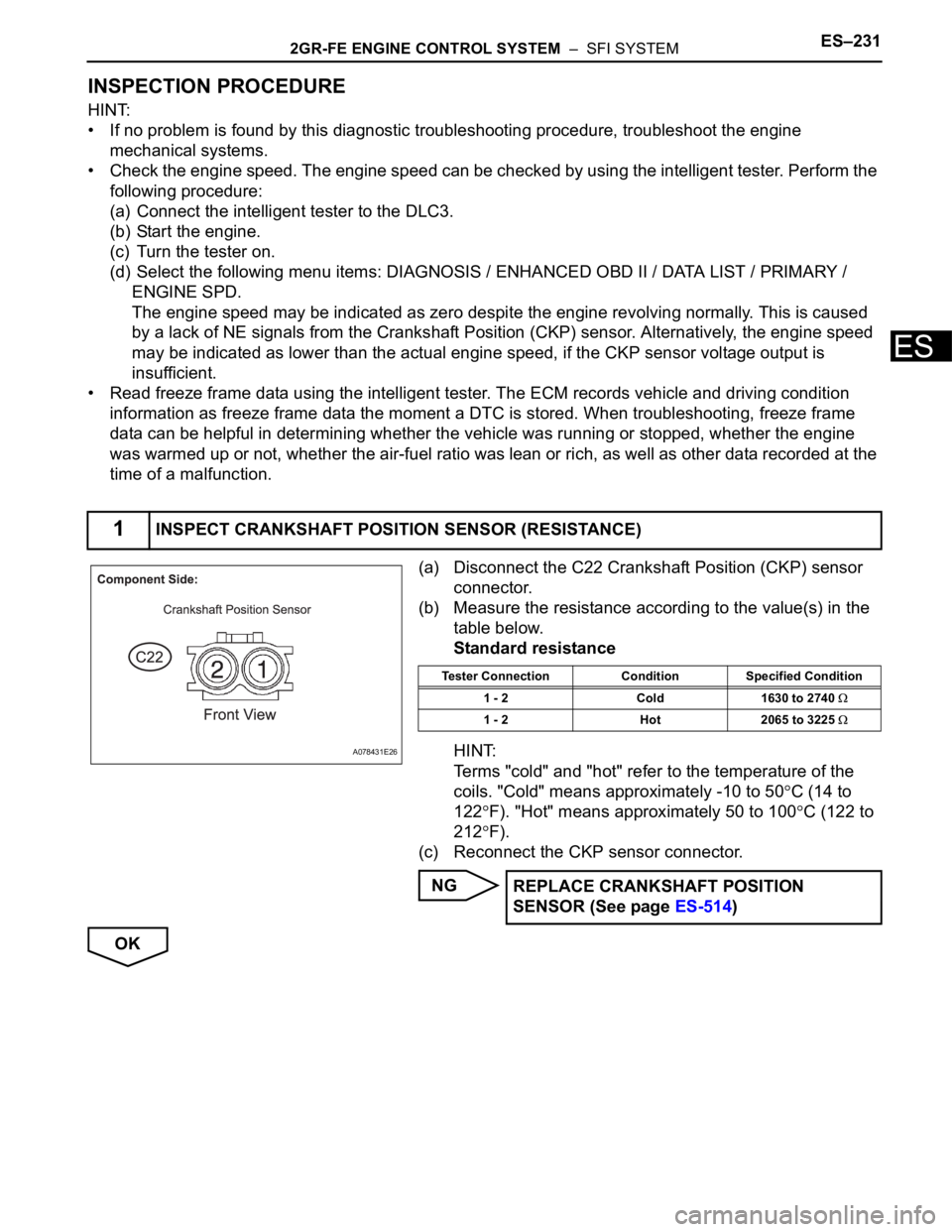
(a) Disconnect the C22 Crankshaft Position (CKP) sensor
connector.
(b) Measure the resistance according to the value(s) in the
table below.
Standard resistance
HINT:
Terms "cold" and "hot" refer to the temperature of the
coils. "Cold" means approximately -10 to 50
C (14 to
122
F). "Hot" means approximately 50 to 100C (122 to
212
F).
(c) Reconnect the CKP sensor connector.
NG
OK
1INSPECT CRANKSHAFT POSITION SENSOR (RESISTANCE)
A078431E26
Tester Connection Condition Specified Condition
1 - 2 Cold 1630 to 2740
1 - 2 Hot 2065 to 3225
REPLACE CRANKSHAFT POSITION
SENSOR (See page ES-514)
Page 574 of 3000

2GR-FE ENGINE CONTROL SYSTEM – SFI SYSTEMES–281
ES
INSPECTION PROCEDURE
NOTICE:
• When a vehicle is brought into the workshop, leave it as it is. Do not change the vehicle
condition. For example, do not tighten the fuel cap.
• Do not disassemble the canister pump module.
• The intelligent tester is required to conduct the following diagnostic troubleshooting
procedure.
(a) Connect the intelligent tester to the DLC3.
(b) Turn the ignition switch to the ON position (do not start
the engine).
(c) Turn the tester on.
(d) Select the following menu items: DIAGNOSIS /
ENHANCED OBD II / DTC INFO / CURRENT CODES.
(e) Read DTCs.
(f) Select the following menu items: DIAGNOSIS /
ENHANCED OBD II / DATA LIST / EVAP / EVAP VAPOR
PRESS.
(g) Read the EVAP (Evaporative Emission) pressure
displayed on the tester.
Result
B
C
A
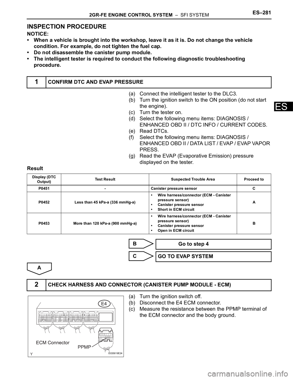
(a) Turn the ignition switch off.
(b) Disconnect the E4 ECM connector.
(c) Measure the resistance between the PPMP terminal of
the ECM connector and the body ground.
1CONFIRM DTC AND EVAP PRESSURE
Display (DTC
Output)Test Result Suspected Trouble Area Proceed to
P0451 - Canister pressure sensor C
P0452 Less than 45 kPa-a (336 mmHg-a)• Wire harness/connector (ECM - Canister
pressure sensor)
• Canister pressure sensor
• Short in ECM circuitA
P0453 More than 120 kPa-a (900 mmHg-a)• Wire harness/connector (ECM - Canister
pressure sensor)
• Canister pressure sensor
• Open in ECM circuitB
Go to step 4
GO TO EVAP SYSTEM
2CHECK HARNESS AND CONNECTOR (CANISTER PUMP MODULE - ECM)
G035619E24
Page 802 of 3000

ES–262GR-FE ENGINE CONTROL SYSTEM – SFI SYSTEM
ES
READINESS MONITOR DRIVE
PAT T E R N
1. PURPOSE OF READINESS TESTS
• The On-Board Diagnostic (OBD II) system is
designed to monitor the performance of emission-
related components, and indicate any detected
abnormalities with DTCs (Diagnostic Trouble Codes).
Since various components need to be monitored in
different driving conditions, the OBD II system is
designed to run separate monitoring programs called
Readiness Monitors.
• The intelligent tester's software must be version 9.0 or
newer to view the Readiness Monitor status. To view
the status, select the following menu items:
DIAGNOSIS / ENHANCED OBD II / MONITOR INFO
/ MONITOR STATUS.
• When the Readiness Monitor status reads COMPL
(complete), the necessary conditions have been met
for running the performance tests for that Readiness
Monitor.
• A generic OBD II scan tool can also be used to view
the Readiness Monitor status.
HINT:
Many Inspection and Maintenance (I/M) programs
require a vehicle's Readiness Monitor status to show
COMPL before beginning emission tests.
The Readiness Monitor will be reset to INCMPL
(incomplete) if:
• The ECM has lost battery power or broken a fuse.
• DTCs have been cleared.
• The conditions for running the Readiness Monitor
have not been met.
If the Readiness Monitor status shows INCMPL, follow
the appropriate Readiness Monitor Drive Pattern to
change the status to COMPL.
CAUTION:
Strictly observe posted speed limits, traffic laws, and
road conditions when performing these drive
patterns.
NOTICE:
These drive patterns represent the fastest method of
satisfying all conditions necessary to achieve
complete status for each specific Readiness
Monitor.
In the event of a drive pattern being interrupted
(possibly due to factors such as traffic conditions),
the drive pattern can be resumed. In most cases, the
Readiness Monitor will still achieve complete status
upon completion of the drive pattern.
To ensure completion of the Readiness Monitors,
avoid sudden changes in vehicle load and speed
(driving up and down hills and/or sudden
acceleration).
Page 2283 of 3000

TIRE AND WHEEL – TIRE PRESSURE WARNING SYSTEMTW–39
TW
HINT:
*1: Displayed only when the ID No. is not registered.
*2: It may take about 5 to 6 minutes until the values
are displayed. If the values are not displayed after a
few minutes, perform troubleshooting according to
the inspection procedure for DTCs C2121/21 to
C2124/24 (See page TW-42).
METER:
2. ACTIVE TEST
Using the intelligent tester to perform ACTIVE TEST
allows the meters, indicators and other items to be
operated without removing any parts. Performing
ACTIVE TEST early in troubleshooting is one way to
save diagnostic time. It is possible to display the DATA
LIST on the intelligent tester during ACTIVE TEST.
(a) Make sure that the ignition switch is off.
(b) Connect the intelligent tester to the DLC3.
(c) Turn the ignition switch to the ON position.
(d) Enter the following menus: DIAGNOSIS / OBD/
MOBD / METER / ACTIVE TEST.
METER:
TIRE TEMP1ID1 temperature in tire/min.: -50C (-58F),
max.: 205
C (401F)Actual tire temperatureIf -50
C (-58F) is displayed,
data has not been received.
TIRE TEMP2ID2 temperature in tire/min.: -50
C (-58F),
max.: 205
C (401F)Actual tire temperatureIf -50
C (-58F) is displayed,
data has not been received.
TIRE TEMP3ID3 temperature in tire/min.: -50
C (-58F),
max.: 205
C (401F)Actual tire temperatureIf -50
C (-58F) is displayed,
data has not been received.
TIRE TEMP4ID4 temperature in tire/min.: -50
C (-58F),
max.: 205
C (401F)Actual tire temperatureIf -50
C (-58F) is displayed,
data has not been received.
BATT VOLT1 ID1 battery voltage/OVER or LESS OVER -
BATT VOLT2 ID2 battery voltage/OVER or LESS OVER -
BATT VOLT3 ID3 battery voltage/OVER or LESS OVER -
BATT VOLT4 ID4 battery voltage/OVER or LESS OVER -
INITIAL SW INFOTire pressure warning reset switch setting
information/WITH or WITHOUTWITH or WITHOUT -
INIT THRESHOLD1ID1 initial threshold of low-pressure/min.: 0 kPa
(0 kgf/cm
2, 0 psi), max.: 637.5 kPa (6.4 kgf/cm2,
93 psi)Tire pressure after initialization -
INIT THRESHOLD2ID2 initial threshold of low-pressure/min.: 0 kPa
(0 kgf/cm
2, 0 psi), max.: 637.5 kPa (6.4 kgf/cm2,
93 psi)Tire pressure after initialization -
INIT THRESHOLD3ID3 initial threshold of low-pressure/min.: 0 kPa
(0 kgf/cm
2, 0 psi), max.: 637.5 kPa (6.4 kgf/cm2,
93 psi)Tire pressure after initialization -
INIT THRESHOLD4ID4 initial threshold of low-pressure/min.: 0 kPa
(0 kgf/cm
2, 0 psi), max.: 637.5 kPa (6.4 kgf/cm2,
93 psi)Tire pressure after initialization -
# CODES Number of DTCs recorded/min.: 0, max.: 255 Min.: 0, Max.: - - Tester Display Measurement Item/Range Normal Condition Diagnostic Note
Tester Display Measurement Item/Range Normal Condition Diagnostic Note
SPEED METERVehicle speed/Min.: 0 km/h (0 mph), Max.: 255
km/h (158 mph)Almost same as actual vehicle speed
(When driving)-
Tester Display Test Part Control Range Diagnostic Note
TIRE PRESS WARN Tire Pressure Warning LightTire Pressure Warning Light is
OFF/ONConfirm that the vehicle is
stopped with the engine idling
Page 2357 of 3000

TIRE AND WHEEL – TIRE PRESSURE WARNING SYSTEMTW–39
TW
HINT:
*1: Displayed only when the ID No. is not registered.
*2: It may take about 5 to 6 minutes until the values
are displayed. If the values are not displayed after a
few minutes, perform troubleshooting according to
the inspection procedure for DTCs C2121/21 to
C2124/24 (See page TW-42).
METER:
2. ACTIVE TEST
Using the intelligent tester to perform ACTIVE TEST
allows the meters, indicators and other items to be
operated without removing any parts. Performing
ACTIVE TEST early in troubleshooting is one way to
save diagnostic time. It is possible to display the DATA
LIST on the intelligent tester during ACTIVE TEST.
(a) Make sure that the ignition switch is off.
(b) Connect the intelligent tester to the DLC3.
(c) Turn the ignition switch to the ON position.
(d) Enter the following menus: DIAGNOSIS / OBD/
MOBD / METER / ACTIVE TEST.
METER:
TIRE TEMP1ID1 temperature in tire/min.: -50C (-58F),
max.: 205
C (401F)Actual tire temperatureIf -50
C (-58F) is displayed,
data has not been received.
TIRE TEMP2ID2 temperature in tire/min.: -50
C (-58F),
max.: 205
C (401F)Actual tire temperatureIf -50
C (-58F) is displayed,
data has not been received.
TIRE TEMP3ID3 temperature in tire/min.: -50
C (-58F),
max.: 205
C (401F)Actual tire temperatureIf -50
C (-58F) is displayed,
data has not been received.
TIRE TEMP4ID4 temperature in tire/min.: -50
C (-58F),
max.: 205
C (401F)Actual tire temperatureIf -50
C (-58F) is displayed,
data has not been received.
BATT VOLT1 ID1 battery voltage/OVER or LESS OVER -
BATT VOLT2 ID2 battery voltage/OVER or LESS OVER -
BATT VOLT3 ID3 battery voltage/OVER or LESS OVER -
BATT VOLT4 ID4 battery voltage/OVER or LESS OVER -
INITIAL SW INFOTire pressure warning reset switch setting
information/WITH or WITHOUTWITH or WITHOUT -
INIT THRESHOLD1ID1 initial threshold of low-pressure/min.: 0 kPa
(0 kgf/cm
2, 0 psi), max.: 637.5 kPa (6.4 kgf/cm2,
93 psi)Tire pressure after initialization -
INIT THRESHOLD2ID2 initial threshold of low-pressure/min.: 0 kPa
(0 kgf/cm
2, 0 psi), max.: 637.5 kPa (6.4 kgf/cm2,
93 psi)Tire pressure after initialization -
INIT THRESHOLD3ID3 initial threshold of low-pressure/min.: 0 kPa
(0 kgf/cm
2, 0 psi), max.: 637.5 kPa (6.4 kgf/cm2,
93 psi)Tire pressure after initialization -
INIT THRESHOLD4ID4 initial threshold of low-pressure/min.: 0 kPa
(0 kgf/cm
2, 0 psi), max.: 637.5 kPa (6.4 kgf/cm2,
93 psi)Tire pressure after initialization -
# CODES Number of DTCs recorded/min.: 0, max.: 255 Min.: 0, Max.: - - Tester Display Measurement Item/Range Normal Condition Diagnostic Note
Tester Display Measurement Item/Range Normal Condition Diagnostic Note
SPEED METERVehicle speed/Min.: 0 km/h (0 mph), Max.: 255
km/h (158 mph)Almost same as actual vehicle speed
(When driving)-
Tester Display Test Part Control Range Diagnostic Note
TIRE PRESS WARN Tire Pressure Warning LightTire Pressure Warning Light is
OFF/ONConfirm that the vehicle is
stopped with the engine idling