Page 111 of 3000
DS–6DRIVE SHAFT – FRONT DRIVE SHAFT
DS
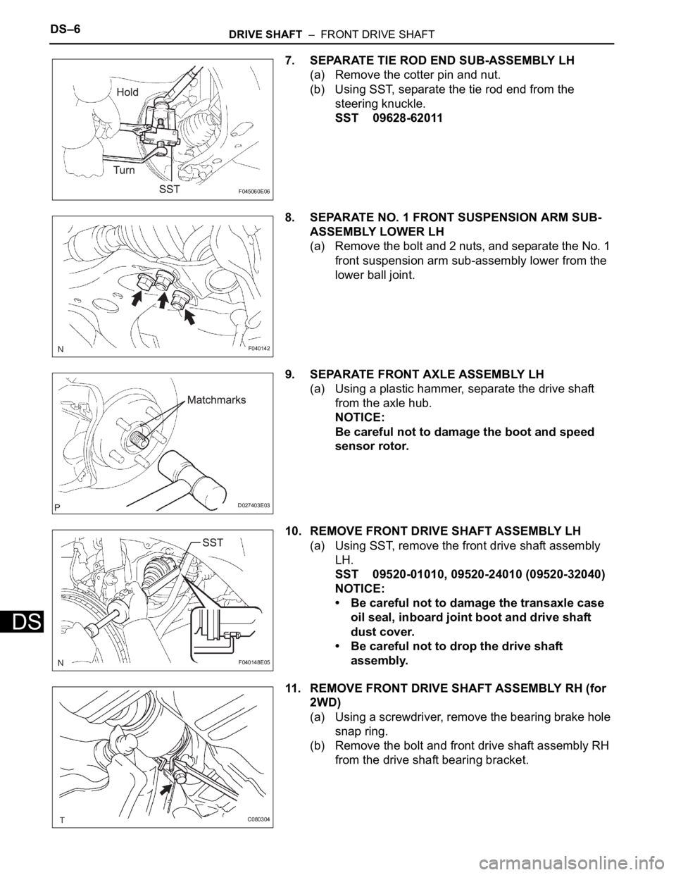
7. SEPARATE TIE ROD END SUB-ASSEMBLY LH
(a) Remove the cotter pin and nut.
(b) Using SST, separate the tie rod end from the
steering knuckle.
SST 09628-62011
8. SEPARATE NO. 1 FRONT SUSPENSION ARM SUB-
ASSEMBLY LOWER LH
(a) Remove the bolt and 2 nuts, and separate the No. 1
front suspension arm sub-assembly lower from the
lower ball joint.
9. SEPARATE FRONT AXLE ASSEMBLY LH
(a) Using a plastic hammer, separate the drive shaft
from the axle hub.
NOTICE:
Be careful not to damage the boot and speed
sensor rotor.
10. REMOVE FRONT DRIVE SHAFT ASSEMBLY LH
(a) Using SST, remove the front drive shaft assembly
LH.
SST 09520-01010, 09520-24010 (09520-32040)
NOTICE:
• Be careful not to damage the transaxle case
oil seal, inboard joint boot and drive shaft
dust cover.
• Be careful not to drop the drive shaft
assembly.
11. REMOVE FRONT DRIVE SHAFT ASSEMBLY RH (for
2WD)
(a) Using a screwdriver, remove the bearing brake hole
snap ring.
(b) Remove the bolt and front drive shaft assembly RH
from the drive shaft bearing bracket.
F045060E06
F040142
D027403E03
F040148E05
C080304
Page 163 of 3000
AH–6AXLE – FRONT AXLE HUB
AH
REMOVAL
HINT:
Replace the RH side using the same procedures as for the
LH side.
1. REMOVE FRONT WHEEL
2. REMOVE FRONT AXLE HUB LH NUT (See page DS-
5)
3. SEPARATE SPEED SENSOR FRONT LH (See page
DS-5)
4. SEPARATE FRONT DISC BRAKE CALIPER
ASSEMBLY LH
(a) Remove the 2 bolts and separate the front disc
brake caliper assembly LH from the steering
knuckle LH.
NOTICE:
Use a string or other device to keep the brake
caliper from hanging down.
5. REMOVE FRONT DISC
6. SEPARATE TIE ROD END SUB-ASSEMBLY LH (See
page DS-6)
7. SEPARATE FRONT SUSPENSION ARM SUB-
ASSEMBLY LOWER NO.1 LH (See page DS-6)
8. REMOVE FRONT AXLE ASSEMBLY LH
(a) Using a plastic hammer, separate the front drive
shaft assembly LH from the front axle hub sub-
assembly LH.
NOTICE:
Be careful not to damage the boot and ABS
speed sensor rotor.
(b) Remove the 2 bolts, nuts and steering knuckle LH
with the front axle nub sub-assembly LH.
C067088
D027403
C083023
Page 181 of 3000
BRAKE CONTROL – ANTI-LOCK BRAKE SYSTEMBC–5
BC
• After the ABS warning light goes off and if
vehicle speed exceeds 50 mph (80 km/h), the
signal check code will be stored again.
Decelerate or stop the vehicle before the
speed reaches 50 mph (80 km/h).
• If the signal check has not been completed,
the ABS warning light blinks while driving
and the ABS system does not operate.
HINT:
When the signal check has been completed, the
ABS warning light goes off while driving and blinks
in the Test Mode pattern while stationary.
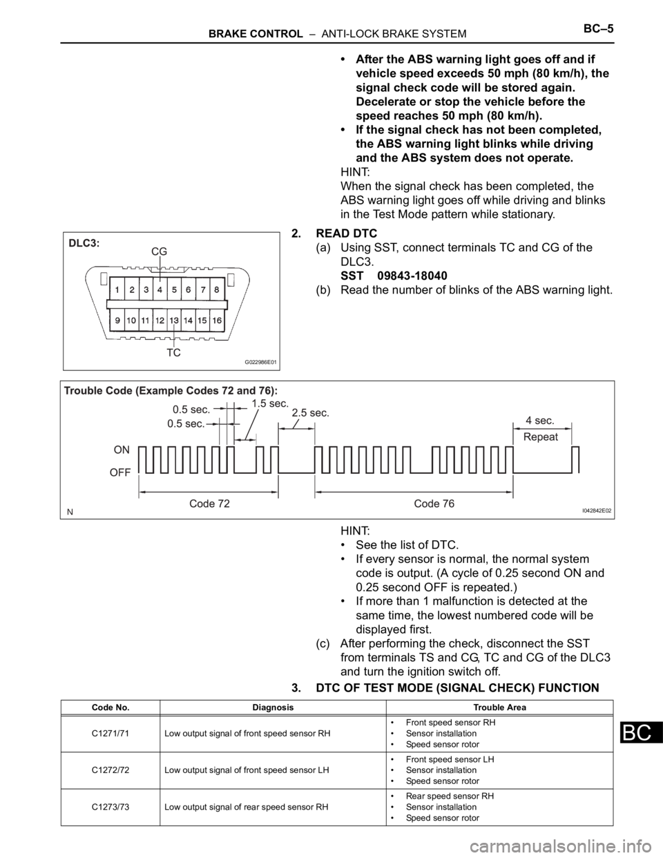
2. READ DTC
(a) Using SST, connect terminals TC and CG of the
DLC3.
SST 09843-18040
(b) Read the number of blinks of the ABS warning light.
HINT:
• See the list of DTC.
• If every sensor is normal, the normal system
code is output. (A cycle of 0.25 second ON and
0.25 second OFF is repeated.)
• If more than 1 malfunction is detected at the
same time, the lowest numbered code will be
displayed first.
(c) After performing the check, disconnect the SST
from terminals TS and CG, TC and CG of the DLC3
and turn the ignition switch off.
3. DTC OF TEST MODE (SIGNAL CHECK) FUNCTION
G022986E01
I042842E02
Code No. Diagnosis Trouble Area
C1271/71 Low output signal of front speed sensor RH• Front speed sensor RH
• Sensor installation
• Speed sensor rotor
C1272/72 Low output signal of front speed sensor LH• Front speed sensor LH
• Sensor installation
• Speed sensor rotor
C1273/73 Low output signal of rear speed sensor RH• Rear speed sensor RH
• Sensor installation
• Speed sensor rotor
Page 182 of 3000
BC–6BRAKE CONTROL – ANTI-LOCK BRAKE SYSTEM
BC
HINT:
The codes in this table are output only in Test Mode
(signal check).
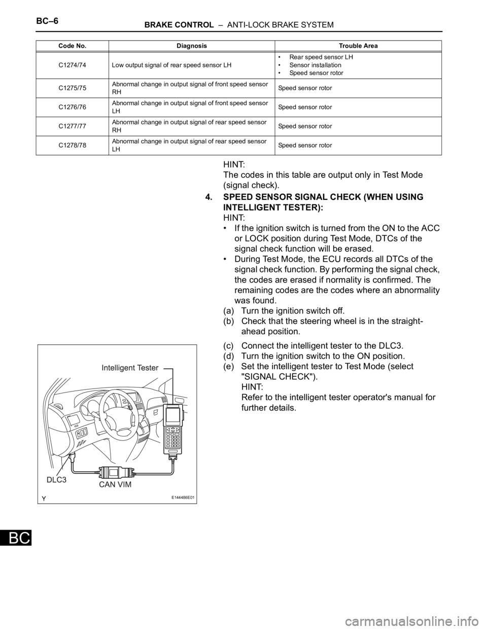
4. SPEED SENSOR SIGNAL CHECK (WHEN USING
INTELLIGENT TESTER):
HINT:
• If the ignition switch is turned from the ON to the ACC
or LOCK position during Test Mode, DTCs of the
signal check function will be erased.
• During Test Mode, the ECU records all DTCs of the
signal check function. By performing the signal check,
the codes are erased if normality is confirmed. The
remaining codes are the codes where an abnormality
was found.
(a) Turn the ignition switch off.
(b) Check that the steering wheel is in the straight-
ahead position.
(c) Connect the intelligent tester to the DLC3.
(d) Turn the ignition switch to the ON position.
(e) Set the intelligent tester to Test Mode (select
"SIGNAL CHECK").
HINT:
Refer to the intelligent tester operator's manual for
further details.
C1274/74 Low output signal of rear speed sensor LH• Rear speed sensor LH
• Sensor installation
• Speed sensor rotor
C1275/75Abnormal change in output signal of front speed sensor
RHSpeed sensor rotor
C1276/76Abnormal change in output signal of front speed sensor
LHSpeed sensor rotor
C1277/77Abnormal change in output signal of rear speed sensor
RHSpeed sensor rotor
C1278/78Abnormal change in output signal of rear speed sensor
LHSpeed sensor rotor Code No. Diagnosis Trouble Area
E144486E01
Page 183 of 3000
BRAKE CONTROL – ANTI-LOCK BRAKE SYSTEMBC–7
BC
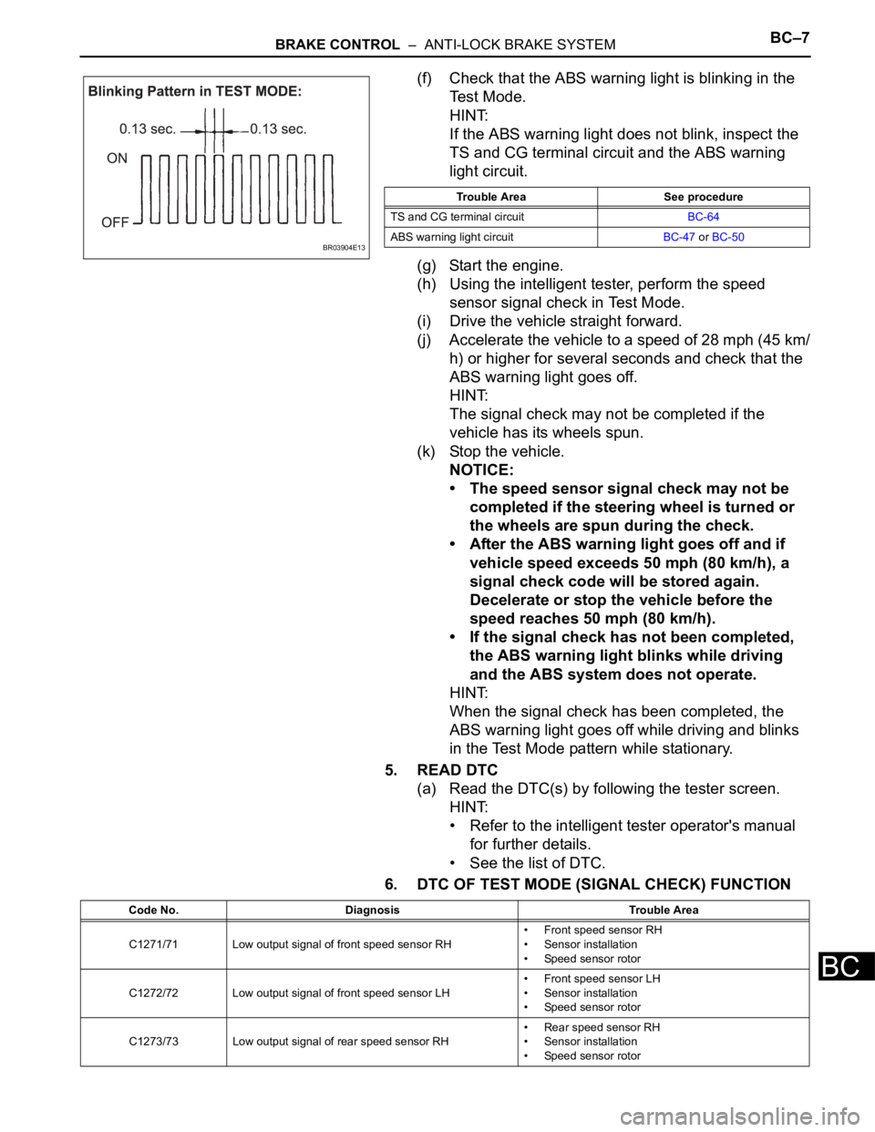
(f) Check that the ABS warning light is blinking in the
Test Mode.
HINT:
If the ABS warning light does not blink, inspect the
TS and CG terminal circuit and the ABS warning
light circuit.
(g) Start the engine.
(h) Using the intelligent tester, perform the speed
sensor signal check in Test Mode.
(i) Drive the vehicle straight forward.
(j) Accelerate the vehicle to a speed of 28 mph (45 km/
h) or higher for several seconds and check that the
ABS warning light goes off.
HINT:
The signal check may not be completed if the
vehicle has its wheels spun.
(k) Stop the vehicle.
NOTICE:
• The speed sensor signal check may not be
completed if the steering wheel is turned or
the wheels are spun during the check.
• After the ABS warning light goes off and if
vehicle speed exceeds 50 mph (80 km/h), a
signal check code will be stored again.
Decelerate or stop the vehicle before the
speed reaches 50 mph (80 km/h).
• If the signal check has not been completed,
the ABS warning light blinks while driving
and the ABS system does not operate.
HINT:
When the signal check has been completed, the
ABS warning light goes off while driving and blinks
in the Test Mode pattern while stationary.
5. READ DTC
(a) Read the DTC(s) by following the tester screen.
HINT:
• Refer to the intelligent tester operator's manual
for further details.
• See the list of DTC.
6. DTC OF TEST MODE (SIGNAL CHECK) FUNCTION
BR03904E13
Trouble Area See procedure
TS and CG terminal circuitBC-64
ABS warning light circuitBC-47 or BC-50
Code No. Diagnosis Trouble Area
C1271/71 Low output signal of front speed sensor RH• Front speed sensor RH
• Sensor installation
• Speed sensor rotor
C1272/72 Low output signal of front speed sensor LH• Front speed sensor LH
• Sensor installation
• Speed sensor rotor
C1273/73 Low output signal of rear speed sensor RH• Rear speed sensor RH
• Sensor installation
• Speed sensor rotor
Page 184 of 3000
BC–8BRAKE CONTROL – ANTI-LOCK BRAKE SYSTEM
BC
HINT:
The codes in this table are output only in Test Mode
(signal check).
C1274/74 Low output signal of rear speed sensor LH• Rear speed sensor LH
• Sensor installation
• Speed sensor rotor
C1275/75Abnormal change in output signal of front speed sensor
RHSpeed sensor rotor
C1276/76Abnormal change in output signal of front speed sensor
LHSpeed sensor rotor
C1277/77Abnormal change in output signal of rear speed sensor
RHSpeed sensor rotor
C1278/78Abnormal change in output signal of rear speed sensor
LHSpeed sensor rotor Code No. Diagnosis Trouble Area
Page 2075 of 3000
DS–22DRIVE SHAFT – REAR DRIVE SHAFT (for 4WD)
DS
REMOVAL
1. REMOVE REAR WHEEL
2. REMOVE TAIL EXHAUST PIPE ASSEMBLY (See page
EX-8)
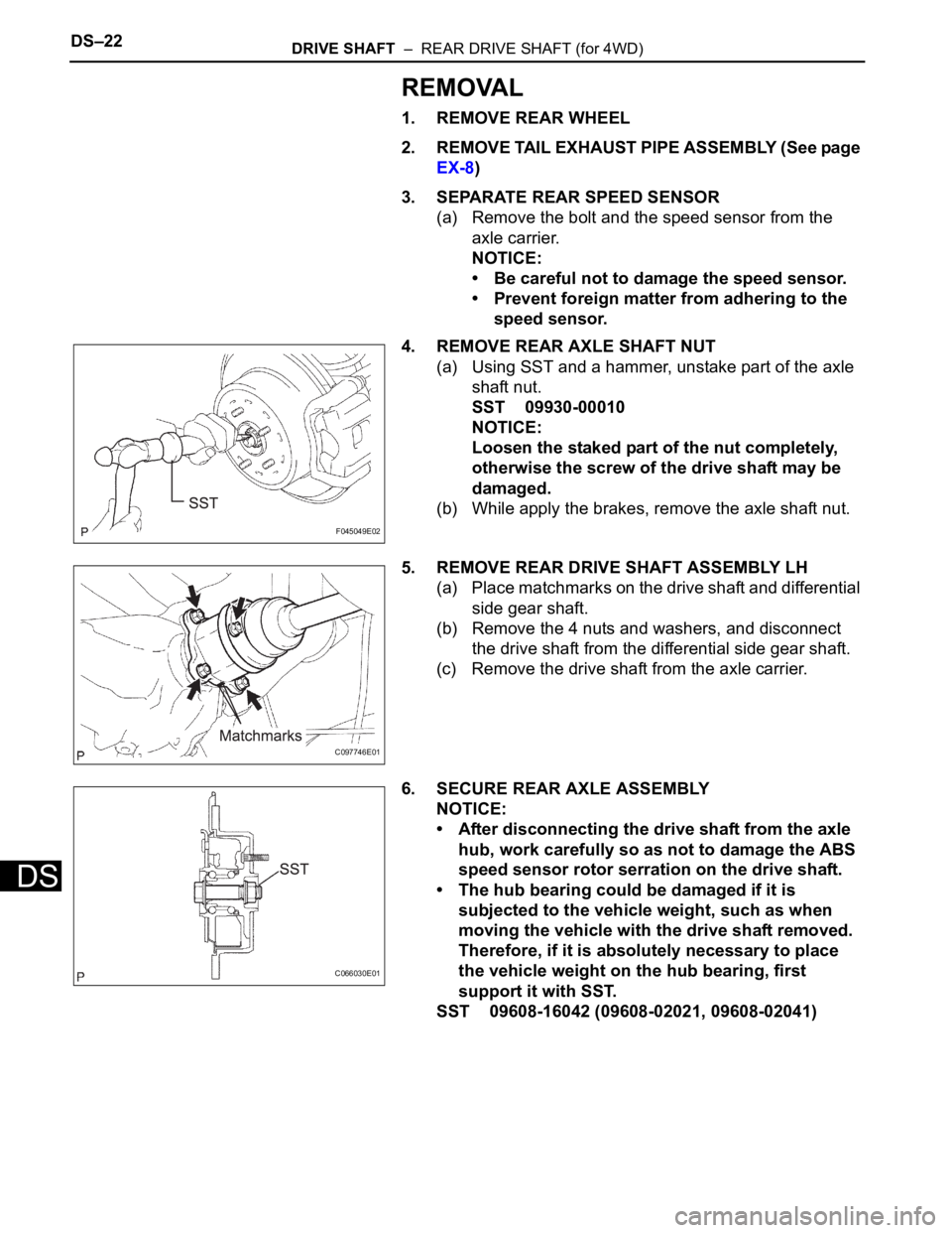
3. SEPARATE REAR SPEED SENSOR
(a) Remove the bolt and the speed sensor from the
axle carrier.
NOTICE:
• Be careful not to damage the speed sensor.
• Prevent foreign matter from adhering to the
speed sensor.
4. REMOVE REAR AXLE SHAFT NUT
(a) Using SST and a hammer, unstake part of the axle
shaft nut.
SST 09930-00010
NOTICE:
Loosen the staked part of the nut completely,
otherwise the screw of the drive shaft may be
damaged.
(b) While apply the brakes, remove the axle shaft nut.
5. REMOVE REAR DRIVE SHAFT ASSEMBLY LH
(a) Place matchmarks on the drive shaft and differential
side gear shaft.
(b) Remove the 4 nuts and washers, and disconnect
the drive shaft from the differential side gear shaft.
(c) Remove the drive shaft from the axle carrier.
6. SECURE REAR AXLE ASSEMBLY
NOTICE:
• After disconnecting the drive shaft from the axle
hub, work carefully so as not to damage the ABS
speed sensor rotor serration on the drive shaft.
• The hub bearing could be damaged if it is
subjected to the vehicle weight, such as when
moving the vehicle with the drive shaft removed.
Therefore, if it is absolutely necessary to place
the vehicle weight on the hub bearing, first
support it with SST.
SST 09608-16042 (09608-02021, 09608-02041)
F045049E02
C097746E01
C066030E01
Page 2081 of 3000
DS–6DRIVE SHAFT – FRONT DRIVE SHAFT
DS
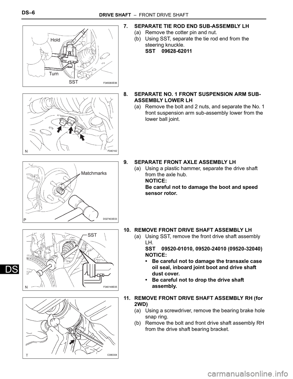
7. SEPARATE TIE ROD END SUB-ASSEMBLY LH
(a) Remove the cotter pin and nut.
(b) Using SST, separate the tie rod end from the
steering knuckle.
SST 09628-62011
8. SEPARATE NO. 1 FRONT SUSPENSION ARM SUB-
ASSEMBLY LOWER LH
(a) Remove the bolt and 2 nuts, and separate the No. 1
front suspension arm sub-assembly lower from the
lower ball joint.
9. SEPARATE FRONT AXLE ASSEMBLY LH
(a) Using a plastic hammer, separate the drive shaft
from the axle hub.
NOTICE:
Be careful not to damage the boot and speed
sensor rotor.
10. REMOVE FRONT DRIVE SHAFT ASSEMBLY LH
(a) Using SST, remove the front drive shaft assembly
LH.
SST 09520-01010, 09520-24010 (09520-32040)
NOTICE:
• Be careful not to damage the transaxle case
oil seal, inboard joint boot and drive shaft
dust cover.
• Be careful not to drop the drive shaft
assembly.
11. REMOVE FRONT DRIVE SHAFT ASSEMBLY RH (for
2WD)
(a) Using a screwdriver, remove the bearing brake hole
snap ring.
(b) Remove the bolt and front drive shaft assembly RH
from the drive shaft bearing bracket.
F045060E06
F040142
D027403E03
F040148E05
C080304