2007 TOYOTA SIENNA brake rotor
[x] Cancel search: brake rotorPage 2548 of 3000
BRAKE CONTROL – ANTI-LOCK BRAKE SYSTEMBC–19
BC
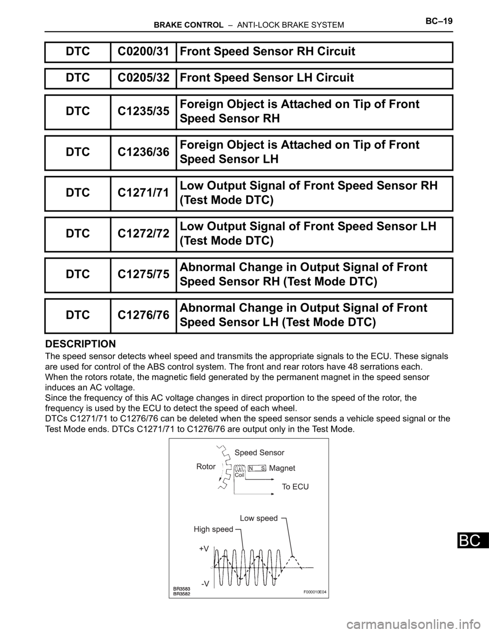
DESCRIPTION
The speed sensor detects wheel speed and transmits the appropriate signals to the ECU. These signals
are used for control of the ABS control system. The front and rear rotors have 48 serrations each.
When the rotors rotate, the magnetic field generated by the permanent magnet in the speed sensor
induces an AC voltage.
Since the frequency of this AC voltage changes in direct proportion to the speed of the rotor, the
frequency is used by the ECU to detect the speed of each wheel.
DTCs C1271/71 to C1276/76 can be deleted when the speed sensor sends a vehicle speed signal or the
Test Mode ends. DTCs C1271/71 to C1276/76 are output only in the Test Mode.
DTC C0200/31 Front Speed Sensor RH Circuit
DTC C0205/32 Front Speed Sensor LH Circuit
DTC C1235/35Foreign Object is Attached on Tip of Front
Speed Sensor RH
DTC C1236/36Foreign Object is Attached on Tip of Front
Speed Sensor LH
DTC C1271/71Low Output Signal of Front Speed Sensor RH
(Test Mode DTC)
DTC C1272/72Low Output Signal of Front Speed Sensor LH
(Test Mode DTC)
DTC C1275/75Abnormal Change in Output Signal of Front
Speed Sensor RH (Test Mode DTC)
DTC C1276/76Abnormal Change in Output Signal of Front
Speed Sensor LH (Test Mode DTC)
F000010E04
Page 2549 of 3000
BC–20BRAKE CONTROL – ANTI-LOCK BRAKE SYSTEM
BC
HINT:
• DTC No. C0200/31 and C1235/35 are for the front speed sensor RH.
• DTC No. C0205/32 and C1236/36 are for the front speed sensor LH.
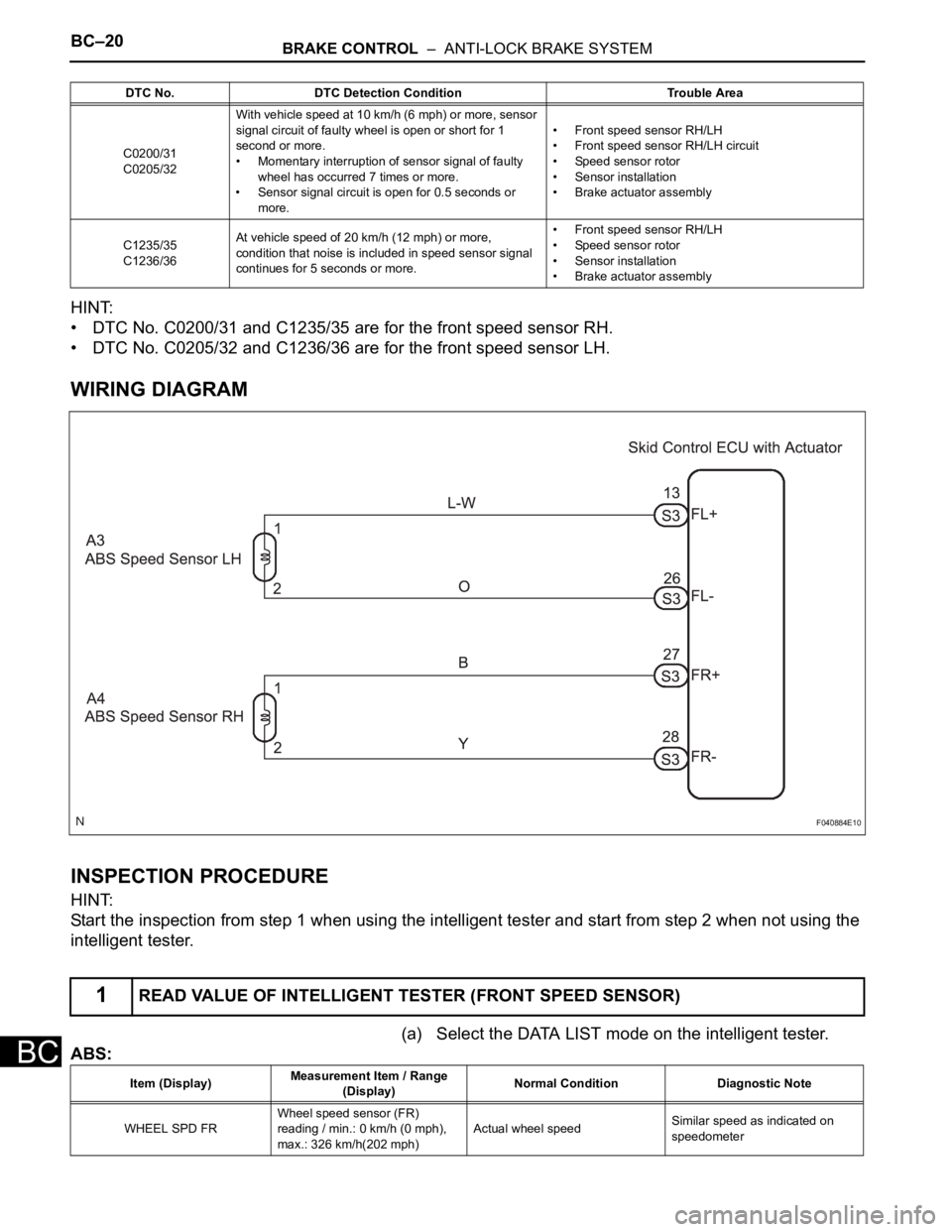
WIRING DIAGRAM
INSPECTION PROCEDURE
HINT:
Start the inspection from step 1 when using the intelligent tester and start from step 2 when not using the
intelligent tester.
(a) Select the DATA LIST mode on the intelligent tester.
ABS:
DTC No. DTC Detection Condition Trouble Area
C0200/31
C0205/32With vehicle speed at 10 km/h (6 mph) or more, sensor
signal circuit of faulty wheel is open or short for 1
second or more.
• Momentary interruption of sensor signal of faulty
wheel has occurred 7 times or more.
• Sensor signal circuit is open for 0.5 seconds or
more.• Front speed sensor RH/LH
• Front speed sensor RH/LH circuit
• Speed sensor rotor
• Sensor installation
• Brake actuator assembly
C1235/35
C1236/36At vehicle speed of 20 km/h (12 mph) or more,
condition that noise is included in speed sensor signal
continues for 5 seconds or more.• Front speed sensor RH/LH
• Speed sensor rotor
• Sensor installation
• Brake actuator assembly
1READ VALUE OF INTELLIGENT TESTER (FRONT SPEED SENSOR)
F040884E10
Item (Display)Measurement Item / Range
(Display)Normal Condition Diagnostic Note
WHEEL SPD FRWheel speed sensor (FR)
reading / min.: 0 km/h (0 mph),
max.: 326 km/h(202 mph)Actual wheel speedSimilar speed as indicated on
speedometer
Page 2552 of 3000
BRAKE CONTROL – ANTI-LOCK BRAKE SYSTEMBC–23
BC
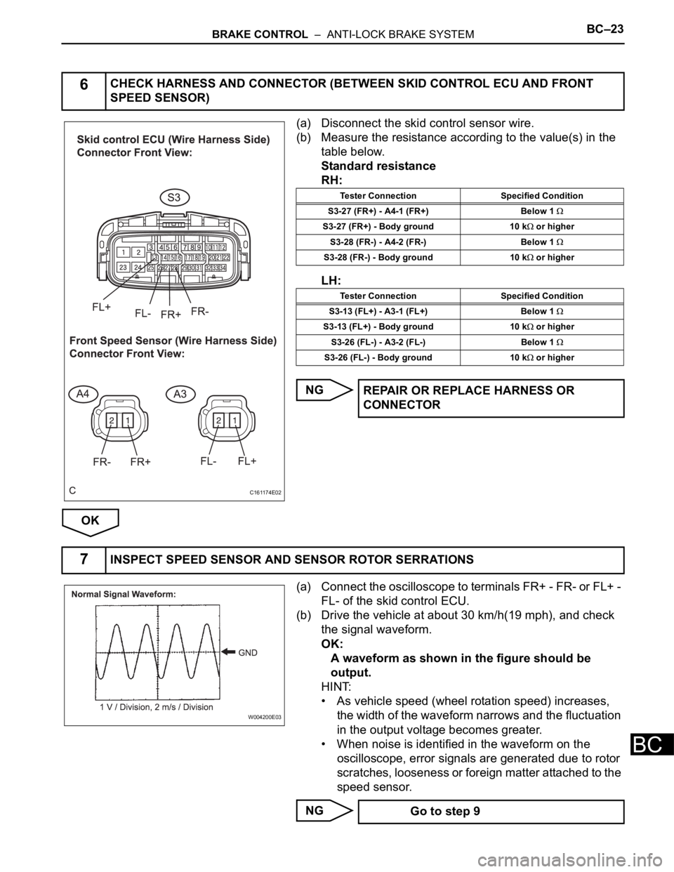
(a) Disconnect the skid control sensor wire.
(b) Measure the resistance according to the value(s) in the
table below.
Standard resistance
RH:
LH:
NG
OK
(a) Connect the oscilloscope to terminals FR+ - FR- or FL+ -
FL- of the skid control ECU.
(b) Drive the vehicle at about 30 km/h(19 mph), and check
the signal waveform.
OK:
A waveform as shown in the figure should be
output.
HINT:
• As vehicle speed (wheel rotation speed) increases,
the width of the waveform narrows and the fluctuation
in the output voltage becomes greater.
• When noise is identified in the waveform on the
oscilloscope, error signals are generated due to rotor
scratches, looseness or foreign matter attached to the
speed sensor.
NG
6CHECK HARNESS AND CONNECTOR (BETWEEN SKID CONTROL ECU AND FRONT
SPEED SENSOR)
C161174E02
Tester Connection Specified Condition
S3-27 (FR+) - A4-1 (FR+) Below 1
S3-27 (FR+) - Body ground 10 k or higher
S3-28 (FR-) - A4-2 (FR-) Below 1
S3-28 (FR-) - Body ground 10 k or higher
Tester Connection Specified Condition
S3-13 (FL+) - A3-1 (FL+) Below 1
S3-13 (FL+) - Body ground 10 k or higher
S3-26 (FL-) - A3-2 (FL-) Below 1
S3-26 (FL-) - Body ground 10 k or higher
REPAIR OR REPLACE HARNESS OR
CONNECTOR
7INSPECT SPEED SENSOR AND SENSOR ROTOR SERRATIONS
W004200E03
Go to step 9
Page 2553 of 3000
BC–24BRAKE CONTROL – ANTI-LOCK BRAKE SYSTEM
BC
OK
(a) Clear the DTCs (See page BC-10).
(b) Drive the vehicle at a speed of approximately 32 km/h
(20 mph) or more for 60 seconds or more.
(c) Check that the same DTCs are recorded (See page BC-
10).
HINT:
Reinstall the sensors, connectors, etc. and restore the
vehicle to its prior condition before rechecking for DTCs.
Result
B
C
A
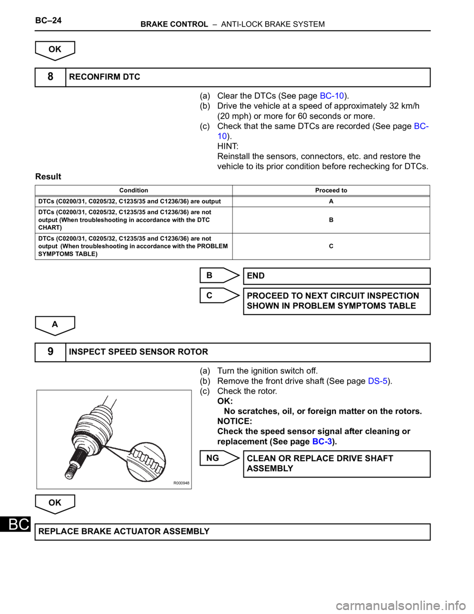
(a) Turn the ignition switch off.
(b) Remove the front drive shaft (See page DS-5).
(c) Check the rotor.
OK:
No scratches, oil, or foreign matter on the rotors.
NOTICE:
Check the speed sensor signal after cleaning or
replacement (See page BC-3).
NG
OK
8RECONFIRM DTC
Condition Proceed to
DTCs (C0200/31, C0205/32, C1235/35 and C1236/36) are output A
DTCs (C0200/31, C0205/32, C1235/35 and C1236/36) are not
output (When troubleshooting in accordance with the DTC
CHART)B
DTCs (C0200/31, C0205/32, C1235/35 and C1236/36) are not
output (When troubleshooting in accordance with the PROBLEM
SYMPTOMS TABLE)C
END
PROCEED TO NEXT CIRCUIT INSPECTION
SHOWN IN PROBLEM SYMPTOMS TABLE
9INSPECT SPEED SENSOR ROTOR
R000948
CLEAN OR REPLACE DRIVE SHAFT
ASSEMBLY
REPLACE BRAKE ACTUATOR ASSEMBLY
Page 2559 of 3000

BRAKE CONTROL – ANTI-LOCK BRAKE SYSTEMBC–25
BC
DESCRIPTION
Refer to DTCs C0200/31, C0205/32, C1235/35, and C1236/36 (See page BC-17).
DTCs C1273/73 to C1278/78 can be deleted when the speed sensor sends a vehicle speed signal or the
Test Mode ends. DTCs C1273/73 to C1278/78 are output only in the Test Mode.
HINT:
• DTC C0210/33 and C1238/38 are for the rear speed sensor RH.
• DTC C0215/34 and C1239/39 are for the rear speed sensor LH.
DTC C0210/33 Rear Speed Sensor RH Circuit
DTC C0215/34 Rear Speed Sensor LH Circuit
DTC C1238/38Foreign Object is Attached on Tip of Rear
Speed Sensor RH
DTC C1239/39Foreign Object is Attached on Tip of Rear
Speed Sensor LH
DTC C1273/73Low Output Signal of Rear Speed Sensor RH
(Test Mode DTC)
DTC C1274/74Low Output Signal of Rear Speed Sensor LH
(Test Mode DTC)
DTC C1277/77Abnormal Change in Output Signal of Rear
Speed Sensor RH (Test Mode DTC)
DTC C1278/78Abnormal Change in Output Signal of Rear
Speed Sensor LH (Test Mode DTC)
DTC No. DTC Detection Condition Trouble Area
C0210/33
C0215/34With vehicle speed at 10 km/h (6 mph) or more, sensor
signal circuit of faulty wheel is open or short for 1
second or more.
• Momentary interruption of sensor signal of faulty
wheel has occurred 7 times or more.
• Sensor signal circuit is open for 0.5 seconds or
more.• Rear speed sensor RH/LH
• Rear speed sensor RH/LH circuit
• Speed sensor rotor
• Sensor installation
• Brake actuator assembly
C1238/38
C1239/39At vehicle speed of 20 km/h (12 mph) or more, condition
that noise is included in speed sensor signal continues
for 5 seconds or more.• Rear speed sensor RH/LH
• Speed sensor rotor
• Sensor installation
• Brake actuator assembly
Page 2563 of 3000
BRAKE CONTROL – ANTI-LOCK BRAKE SYSTEMBC–29
BC
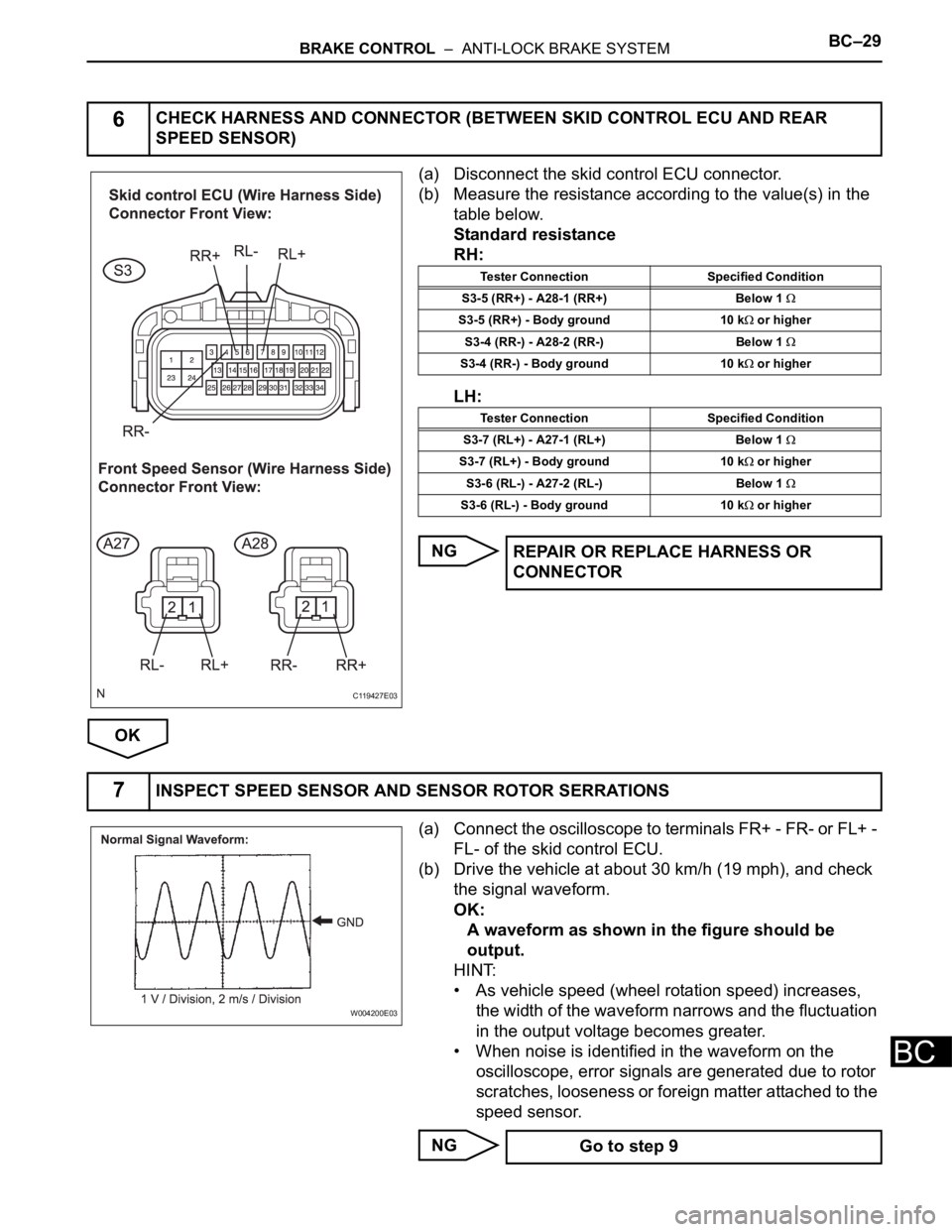
(a) Disconnect the skid control ECU connector.
(b) Measure the resistance according to the value(s) in the
table below.
Standard resistance
RH:
LH:
NG
OK
(a) Connect the oscilloscope to terminals FR+ - FR- or FL+ -
FL- of the skid control ECU.
(b) Drive the vehicle at about 30 km/h (19 mph), and check
the signal waveform.
OK:
A waveform as shown in the figure should be
output.
HINT:
• As vehicle speed (wheel rotation speed) increases,
the width of the waveform narrows and the fluctuation
in the output voltage becomes greater.
• When noise is identified in the waveform on the
oscilloscope, error signals are generated due to rotor
scratches, looseness or foreign matter attached to the
speed sensor.
NG
6CHECK HARNESS AND CONNECTOR (BETWEEN SKID CONTROL ECU AND REAR
SPEED SENSOR)
C119427E03
Tester Connection Specified Condition
S3-5 (RR+) - A28-1 (RR+) Below 1
S3-5 (RR+) - Body ground 10 k or higher
S3-4 (RR-) - A28-2 (RR-) Below 1
S3-4 (RR-) - Body ground 10 k or higher
Tester Connection Specified Condition
S3-7 (RL+) - A27-1 (RL+) Below 1
S3-7 (RL+) - Body ground 10 k or higher
S3-6 (RL-) - A27-2 (RL-) Below 1
S3-6 (RL-) - Body ground 10 k or higher
REPAIR OR REPLACE HARNESS OR
CONNECTOR
7INSPECT SPEED SENSOR AND SENSOR ROTOR SERRATIONS
W004200E03
Go to step 9
Page 2564 of 3000
BC–30BRAKE CONTROL – ANTI-LOCK BRAKE SYSTEM
BC
OK
(a) Clear the DTCs (See page BC-10).
(b) Drive the vehicle at a speed of approximately 32 km/h
(20 mph) or more for 60 seconds or more.
(c) Check that the same DTCs are recorded (See page BC-
10).
HINT:
Reinstall the sensors, connectors, etc. and restore the
vehicle to its prior condition before rechecking for DTCs.
Result
B
C
A
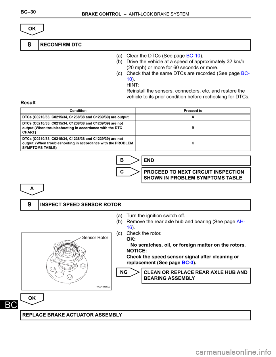
(a) Turn the ignition switch off.
(b) Remove the rear axle hub and bearing (See page AH-
16).
(c) Check the rotor.
OK:
No scratches, oil, or foreign matter on the rotors.
NOTICE:
Check the speed sensor signal after cleaning or
replacement (See page BC-3).
NG
OK
8RECONFIRM DTC
Condition Proceed to
DTCs (C0210/33, C0215/34, C1238/38 and C1239/39) are output A
DTCs (C0210/33, C0215/34, C1238/38 and C1239/39) are not
output (When troubleshooting in accordance with the DTC
CHART)B
DTCs (C0210/33, C0215/34, C1238/38 and C1239/39) are not
output (When troubleshooting in accordance with the PROBLEM
SYMPTOMS TABLE)C
END
PROCEED TO NEXT CIRCUIT INSPECTION
SHOWN IN PROBLEM SYMPTOMS TABLE
9INSPECT SPEED SENSOR ROTOR
W004846E02
CLEAN OR REPLACE REAR AXLE HUB AND
BEARING ASSEMBLY
REPLACE BRAKE ACTUATOR ASSEMBLY
Page 2570 of 3000
BC–190BRAKE CONTROL – REAR SPEED SENSOR (for 2WD)
BC
REMOVAL
HINT:
Remove the RH by the same procedure as the LH side.
1. REMOVE REAR WHEEL
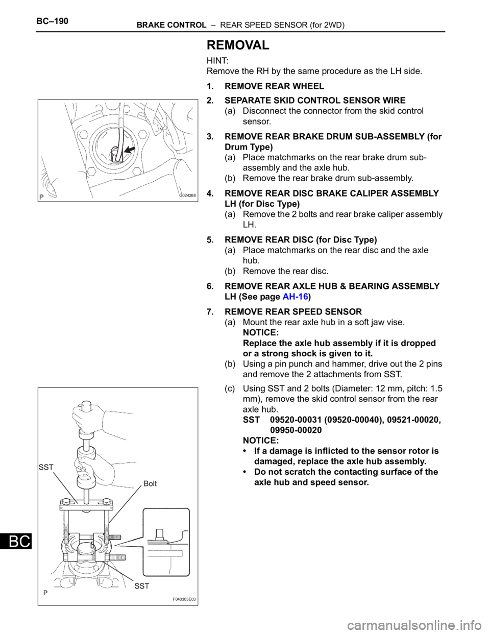
2. SEPARATE SKID CONTROL SENSOR WIRE
(a) Disconnect the connector from the skid control
sensor.
3. REMOVE REAR BRAKE DRUM SUB-ASSEMBLY (for
Drum Type)
(a) Place matchmarks on the rear brake drum sub-
assembly and the axle hub.
(b) Remove the rear brake drum sub-assembly.
4. REMOVE REAR DISC BRAKE CALIPER ASSEMBLY
LH (for Disc Type)
(a) Remove the 2 bolts and rear brake caliper assembly
LH.
5. REMOVE REAR DISC (for Disc Type)
(a) Place matchmarks on the rear disc and the axle
hub.
(b) Remove the rear disc.
6. REMOVE REAR AXLE HUB & BEARING ASSEMBLY
LH (See page AH-16)
7. REMOVE REAR SPEED SENSOR
(a) Mount the rear axle hub in a soft jaw vise.
NOTICE:
Replace the axle hub assembly if it is dropped
or a strong shock is given to it.
(b) Using a pin punch and hammer, drive out the 2 pins
and remove the 2 attachments from SST.
(c) Using SST and 2 bolts (Diameter: 12 mm, pitch: 1.5
mm), remove the skid control sensor from the rear
axle hub.
SST 09520-00031 (09520-00040), 09521-00020,
09950-00020
NOTICE:
• If a damage is inflicted to the sensor rotor is
damaged, replace the axle hub assembly.
• Do not scratch the contacting surface of the
axle hub and speed sensor.
G024268
F040303E03