2007 TOYOTA SIENNA ignition circuit
[x] Cancel search: ignition circuitPage 60 of 3000

IN–30INTRODUCTION – HOW TO TROUBLESHOOT ECU CONTROLLED SYSTEMS
IN
HOW TO TROUBLESHOOT ECU
CONTROLLED SYSTEMS
GENERAL INFORMATION
A large number of ECU controlled systems are used in the
SIENNA. In general, ECU controlled systems are considered
to be very intricate, requiring a high level of technical
knowledge to troubleshoot. However, most problem checking
procedures only involve inspecting the ECU controlled
system's circuits one by one. An adequate understanding of
the system and a basic knowledge of electricity is enough to
perform effective troubleshooting, accurate diagnoses and
necessary repairs.
FOR USING INTELLIGENT TESTER
– Before using the intelligent tester, read the tester
operator's manual thoroughly.
– If the tester cannot communicate with the ECU controlled
systems when the tester is connected to the DLC3 with the
ignition switch on and the tester turned on, there is a
problem on the vehicle side or tester side.
(1) If communication is normal when the tester is
connected to another vehicle, inspect the diagnosis
data link line (Bus (+) line) or ECU power circuit of the
vehicle.
(2) If communication is still not possible when the tester is
connected to another vehicle, the problem is probably
in the tester itself. Perform the Self Test procedures
outlined in the tester operator's manual.
Page 64 of 3000

IN–34INTRODUCTION – HOW TO TROUBLESHOOT ECU CONTROLLED SYSTEMS
IN
3. CHECK FOR SHORT CIRCUIT
(a) If the wire harness is ground shorted (Fig. 5), locate
the section by conducting a resistance check with
the body ground (below).
(b) Check the resistance with the body ground.
(1) Disconnect connectors A and C and measure
the resistance.
Standard resistance (Fig. 6)
HINT:
Measure the resistance while lightly shaking the
wire harness vertically and horizontally. If your
results match the examples above, an open
circuit exists between terminal 1 of connector A
and terminal 1 of connector C.
(2) Disconnect connector B and measure the
resistance.
Standard resistance (Fig. 7)
If the results match the examples above, a short
circuit exists between terminal 1 of connector B2
and terminal 1 of connector C.
4. CHECK AND REPLACE ECU
NOTICE:
• The connector should not be disconnected from
the ECU. Perform the inspection from the
backside of the connector on the wire harness
side.
• When no measuring condition is specified,
perform the inspection with the engine stopped
and the ignition switch on.
• Check that the connectors are fully seated. Check
for loose, corroded or broken wires.
Z017008E02
Z017009E02
Tester Connection Specified Condition
Connector A terminal 1 - Body
groundBelow 1
Connector A terminal 2 - Body
ground10 k or higher
Z017808E02
Tester Connection Specified Condition
Connector A terminal 1 - Body
ground10 k
or higher
Connector B2 terminal 2 - Body
ground Below 1
Page 180 of 3000
BC–4BRAKE CONTROL – ANTI-LOCK BRAKE SYSTEM
BC
TEST MODE PROCEDURE
1. SPEED SENSOR SIGNAL CHECK (WHEN USING SST
CHECK WIRE):
HINT:
• If the ignition switch is turned from the ON to the ACC
or LOCK position during Test Mode, the DTCs of the
signal check function will be erased.
(a) Turn the ignition switch off.
(b) Check that the steering wheel is in the straight-
ahead position and move the shift lever to the P
position (Automatic Transmission) or apply the
parking brake (Manual Transmission).
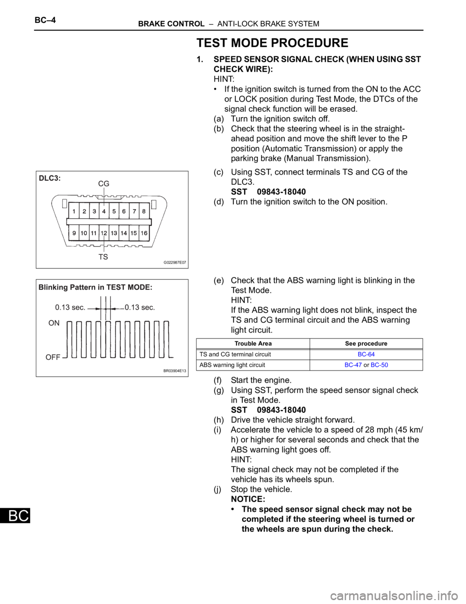
(c) Using SST, connect terminals TS and CG of the
DLC3.
SST 09843-18040
(d) Turn the ignition switch to the ON position.
(e) Check that the ABS warning light is blinking in the
Test Mode.
HINT:
If the ABS warning light does not blink, inspect the
TS and CG terminal circuit and the ABS warning
light circuit.
(f) Start the engine.
(g) Using SST, perform the speed sensor signal check
in Test Mode.
SST 09843-18040
(h) Drive the vehicle straight forward.
(i) Accelerate the vehicle to a speed of 28 mph (45 km/
h) or higher for several seconds and check that the
ABS warning light goes off.
HINT:
The signal check may not be completed if the
vehicle has its wheels spun.
(j) Stop the vehicle.
NOTICE:
• The speed sensor signal check may not be
completed if the steering wheel is turned or
the wheels are spun during the check.
G022987E07
BR03904E13
Trouble Area See procedure
TS and CG terminal circuitBC-64
ABS warning light circuitBC-47 or BC-50
Page 318 of 3000
2GR-FE ENGINE CONTROL SYSTEM – SFI SYSTEMES–1
ES
SFI SYSTEM
PRECAUTION
1. INITIALIZATION
NOTICE:
• Perform RESET MEMORY (AT initialization) when
replacing the automatic transaxle assembly, engine
assembly or ECM (See page AX-16).
• Perform REGISTRATION (VIN registration) when
replacing the ECM (See page ES-15).
HINT:
Initialization cannot be completed by only removing the
battery.
2. FOR USING INTELLIGENT TESTER
CAUTION:
Observe the following items for safety reasons:
• Before using the tester, read the instruction
manual.
• Prevent the tester cable from being caught on the
pedals, shift lever and steering wheel when
driving with the tester connected to the vehicle.
• When driving the vehicle for testing purposes
using the tester, two persons are required. One is
for driving the vehicle, and the other operates the
tester.
3. FOR USING BATTERY DURING INSPECTION
(a) While using the battery during inspection, do not
bring the positive and negative tester probes too
close to each other as a short circuit may occur.
4. COOLING FAN SYSTEM
NOTICE:
• When the ignition switch is turned off and the engine
temperature is high, the cooling fans may operate for
approximately 3 minutes.
• After turning the ignition switch off, keep hands and
objects away from the fans when they are operating.
HINT:
If all of the following are met for a certain period of time during
a few minute period immediately before the engine is
stopped, the electric fans will continue to operate for 3
minutes after the engine is stopped. This is performed to
ensure restartability and stabilize idle speed.
– The intelligent tester indicates a very high coolant
temperature.
– The intelligent tester indicates a high outside air
temperature.
– The vehicle has been driven under high load (driving on an
uphill or equivalent).
The following sensors are used for this control:
– Coolant temperature sensor
– Outside air temperature sensor
–MAF sensor
– Vehicle speed sensors
Page 320 of 3000

ES–2522GR-FE ENGINE CONTROL SYSTEM – SFI SYSTEM
ES
DESCRIPTION
The exhaust camshaft's Variable Valve Timing (VVT) sensor consists of a magnet and MRE (Magneto
Resistance Element).
The exhaust camshaft has a sensor plate with 3 teeth on its outer circumference.
When the exhaust camshaft rotates, changes occur in the air gaps between the 3 teeth and MRE, which
affects the magnet. As a result, the resistance of the MRE material fluctuates. The VVT sensor converts
the exhaust camshaft rotation data to pulse signals, uses the pulse signals to determine the camshaft
angle, and sends it to the ECM.
MONITOR DESCRIPTION
If no signal is transmitted by the VVT (for exhaust camshaft) sensor despite the engine revolving, or the
rotations of the exhaust camshaft and the crankshaft are not synchronized, the ECM interprets this as a
malfunction of the sensor.
DTC P0365 Camshaft Position Sensor "B" Circuit (Bank 1)
DTC P0367Camshaft Position Sensor "B" Circuit Low
Input (Bank 1)
DTC P0368Camshaft Position Sensor "B" Circuit High
Input (Bank 1)
DTC P0390 Camshaft Position Sensor "B" Circuit (Bank 2)
DTC P0392Camshaft Position Sensor "B" Circuit Low
Input (Bank 2)
DTC P0393Camshaft Position Sensor "B" Circuit High
Input (Bank 2)
DTC No. DTC Detection Condition Trouble Area
P0365
P0390• Input voltage to ECM remains 0.3 V or less, or 4.7
V or higher for more than 5 seconds, when 2 or
more seconds have elapsed after turning ignition
switch ON position
(1 trip detection logic)
• No VVT sensor signal to ECM during cranking
(1 trip detection logic)• Open or short in VVT sensor for exhaust camshaft
circuit
• VVT sensor for exhaust camshaft
• Exhaust camshaft
• Jumped tooth of timing chain
•ECM
P0367
P0392Output voltage of VVT sensor is 0.3 V or less for 5
seconds
(1 trip detection logic)• Open or short in VVT sensor for exhaust camshaft
circuit
• VVT sensor for exhaust camshaft
• Exhaust camshaft
• Jumped tooth of timing chain
•ECM
P0368
P0393Output voltage of VVT sensor is 4.7 V or more for 5
seconds
(1 trip detection logic)• Open or short in VVT sensor for exhaust camshaft
circuit
• VVT sensor for exhaust camshaft
• Exhaust camshaft
• Jumped tooth of timing chain
•ECM
Page 341 of 3000
2GR-FE ENGINE CONTROL SYSTEM – SFI SYSTEMES–15
ES
BASIC INSPECTION
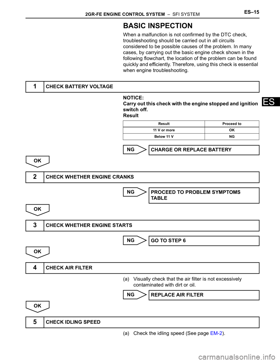
When a malfunction is not confirmed by the DTC check,
troubleshooting should be carried out in all circuits
considered to be possible causes of the problem. In many
cases, by carrying out the basic engine check shown in the
following flowchart, the location of the problem can be found
quickly and efficiently. Therefore, using this check is essential
when engine troubleshooting.
NOTICE:
Carry out this check with the engine stopped and ignition
switch off.
Result
NG
OK
NG
OK
NG
OK
(a) Visually check that the air filter is not excessively
contaminated with dirt or oil.
NG
OK
(a) Check the idling speed (See page EM-2).
1CHECK BATTERY VOLTAGE
Result Proceed to
11 V or more OK
Below 11 V NG
CHARGE OR REPLACE BATTERY
2CHECK WHETHER ENGINE CRANKS
PROCEED TO PROBLEM SYMPTOMS
TA B L E
3CHECK WHETHER ENGINE STARTS
GO TO STEP 6
4CHECK AIR FILTER
REPLACE AIR FILTER
5CHECK IDLING SPEED
Page 357 of 3000
2GR-FE ENGINE CONTROL SYSTEM – SFI SYSTEMES–31
ES
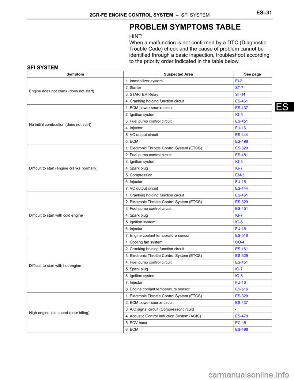
PROBLEM SYMPTOMS TABLE
HINT:
When a malfunction is not confirmed by a DTC (Diagnostic
Trouble Code) check and the cause of problem cannot be
identified through a basic inspection, troubleshoot according
to the priority order indicated in the table below.
SFI SYSTEM
Symptom Suspected Area See page
Engine does not crank (does not start)1. Immobilizer systemEI-2
2. StarterST-7
3. STARTER RelayST-14
4. Cranking holding function circuitES-461
No initial combustion (does not start)1. ECM power source circuitES-437
2. Ignition systemIG-5
3. Fuel pump control circuitES-451
4. InjectorFU-16
5. VC output circuitES-444
6. ECMES-498
Difficult to start (engine cranks normally)1. Electronic Throttle Control System (ETCS)ES-329
2. Fuel pump control circuitES-451
3. Ignition systemIG-5
4. Spark plugIG-7
5. CompressionEM-3
6. InjectorFU-16
7. VC output circuitES-444
Difficult to start with cold engine1. Cranking holding function circuitES-461
2. Electronic Throttle Control System (ETCS)ES-329
3. Fuel pump control circuitES-451
4. Spark plugIG-7
5. Ignition systemIG-6
6. InjectorFU-16
7. Engine coolant temperature sensorES-516
Difficult to start with hot engine1. Cooling fan systemCO-4
2. Cranking holding function circuitES-461
3. Electronic Throttle Control System (ETCS)ES-329
4. Fuel pump control circuitES-451
5. Spark plugIG-7
6. Ignition systemIG-5
7. InjectorFU-16
8. Engine coolant temperature sensorES-516
High engine idle speed (poor idling)1. Electronic Throttle Control System (ETCS)ES-329
2. ECM power source circuitES-437
3. A/C signal circuit (Compressor circuit) -
4. Acoustic Control Induction System (ACIS)ES-470
5. PCV hoseEC-15
6. ECMES-498
Page 358 of 3000
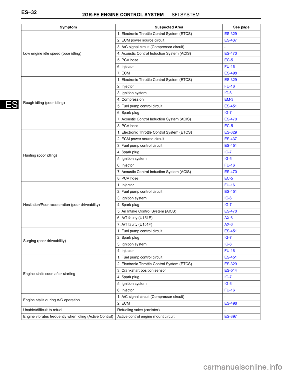
ES–322GR-FE ENGINE CONTROL SYSTEM – SFI SYSTEM
ES
Low engine idle speed (poor idling)1. Electronic Throttle Control System (ETCS)ES-329
2. ECM power source circuitES-437
3. A/C signal circuit (Compressor circuit) -
4. Acoustic Control Induction System (ACIS)ES-470
5. PCV hoseEC-5
6. InjectorFU-16
7. ECMES-498
Rough idling (poor idling)1. Electronic Throttle Control System (ETCS)ES-329
2. InjectorFU-16
3. Ignition systemIG-6
4. CompressionEM-3
5. Fuel pump control circuitES-451
6. Spark plugIG-7
7. Acoustic Control Induction System (ACIS)ES-470
8. PCV hoseEC-5
Hunting (poor idling)1. Electronic Throttle Control System (ETCS)ES-329
2. ECM power source circuitES-437
3. Fuel pump control circuitES-451
4. Spark plugIG-7
5. Ignition systemIG-6
6. InjectorFU-16
7. Acoustic Control Induction System (ACIS)ES-470
8. PCV hoseEC-5
Hesitation/Poor acceleration (poor driveability)1. InjectorFU-16
2. Fuel pump control circuitES-451
3. Ignition systemIG-6
4. Spark plugIG-7
5. Air Intake Control System (AICS)ES-470
6. A/T faulty (U151E)AX-6
7. A/T faulty (U151F)AX-6
Surging (poor driveability)1. Fuel pump control circuitES-451
2. Spark plugIG-7
3. Ignition systemIG-6
4. InjectorFU-16
Engine stalls soon after starting1. Fuel pump control circuitES-451
2. Electronic Throttle Control System (ETCS)ES-329
3. Crankshaft position sensorES-514
4. Spark plugIG-7
5. Ignition systemIG-6
6. InjectorFU-16
Engine stalls during A/C operation1. A/C signal circuit (Compressor circuit) -
2. ECMES-498
Unable/difficult to refuel Refueling valve (canister) -
Engine vibrates frequently when idling (Active Control) Active control engine mount circuitES-397 Symptom Suspected Area See page