Page 2076 of 3000

DRIVE SHAFT – REAR DRIVE SHAFT (for 4WD)DS–23
DS
DISASSEMBLY
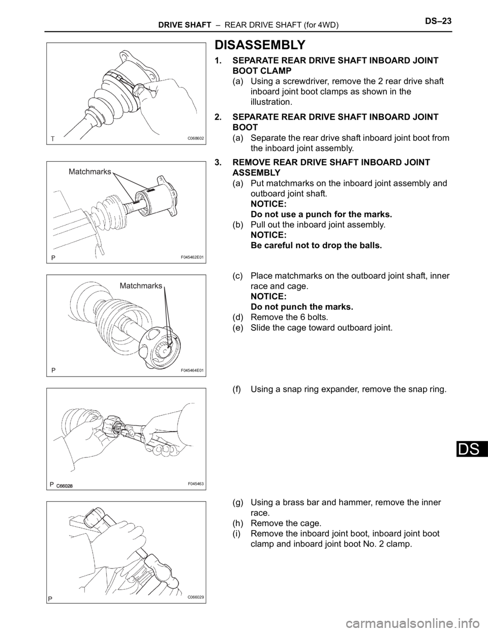
1. SEPARATE REAR DRIVE SHAFT INBOARD JOINT
BOOT CLAMP
(a) Using a screwdriver, remove the 2 rear drive shaft
inboard joint boot clamps as shown in the
illustration.
2. SEPARATE REAR DRIVE SHAFT INBOARD JOINT
BOOT
(a) Separate the rear drive shaft inboard joint boot from
the inboard joint assembly.
3. REMOVE REAR DRIVE SHAFT INBOARD JOINT
ASSEMBLY
(a) Put matchmarks on the inboard joint assembly and
outboard joint shaft.
NOTICE:
Do not use a punch for the marks.
(b) Pull out the inboard joint assembly.
NOTICE:
Be careful not to drop the balls.
(c) Place matchmarks on the outboard joint shaft, inner
race and cage.
NOTICE:
Do not punch the marks.
(d) Remove the 6 bolts.
(e) Slide the cage toward outboard joint.
(f) Using a snap ring expander, remove the snap ring.
(g) Using a brass bar and hammer, remove the inner
race.
(h) Remove the cage.
(i) Remove the inboard joint boot, inboard joint boot
clamp and inboard joint boot No. 2 clamp.
C068602
F045462E01
F045464E01
F045463
C066029
Page 2098 of 3000

DRIVE SHAFT – REAR DRIVE SHAFT (for 4WD)DS–23
DS
DISASSEMBLY
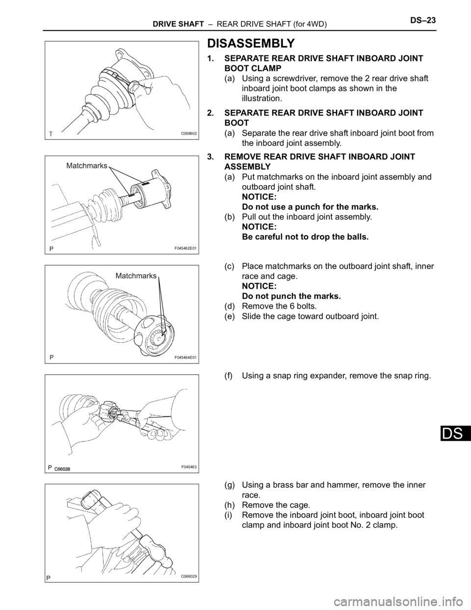
1. SEPARATE REAR DRIVE SHAFT INBOARD JOINT
BOOT CLAMP
(a) Using a screwdriver, remove the 2 rear drive shaft
inboard joint boot clamps as shown in the
illustration.
2. SEPARATE REAR DRIVE SHAFT INBOARD JOINT
BOOT
(a) Separate the rear drive shaft inboard joint boot from
the inboard joint assembly.
3. REMOVE REAR DRIVE SHAFT INBOARD JOINT
ASSEMBLY
(a) Put matchmarks on the inboard joint assembly and
outboard joint shaft.
NOTICE:
Do not use a punch for the marks.
(b) Pull out the inboard joint assembly.
NOTICE:
Be careful not to drop the balls.
(c) Place matchmarks on the outboard joint shaft, inner
race and cage.
NOTICE:
Do not punch the marks.
(d) Remove the 6 bolts.
(e) Slide the cage toward outboard joint.
(f) Using a snap ring expander, remove the snap ring.
(g) Using a brass bar and hammer, remove the inner
race.
(h) Remove the cage.
(i) Remove the inboard joint boot, inboard joint boot
clamp and inboard joint boot No. 2 clamp.
C068602
F045462E01
F045464E01
F045463
C066029
Page 2114 of 3000

DF–16DIFFERENTIAL – REAR DIFFERENTIAL CARRIER
DF
DISASSEMBLY
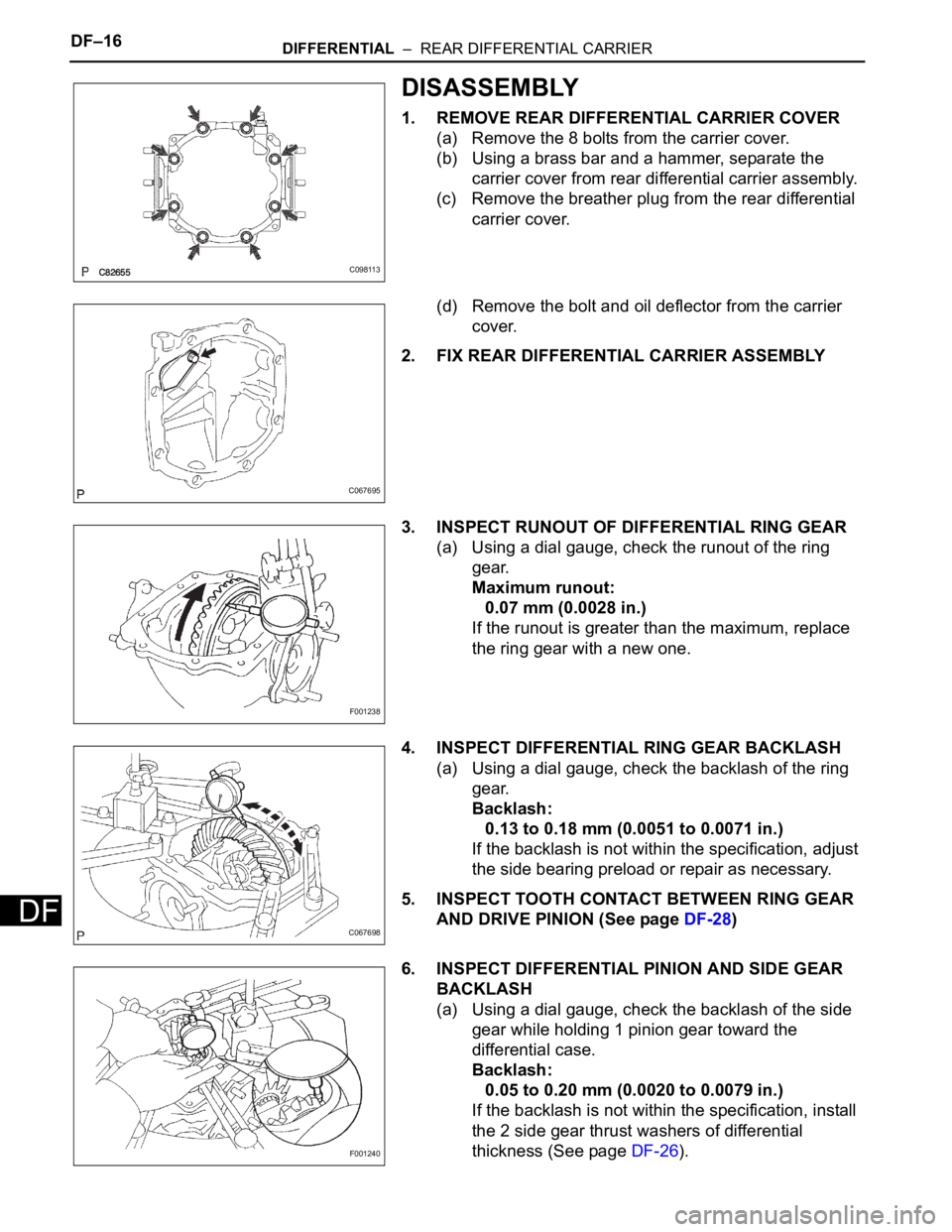
1. REMOVE REAR DIFFERENTIAL CARRIER COVER
(a) Remove the 8 bolts from the carrier cover.
(b) Using a brass bar and a hammer, separate the
carrier cover from rear differential carrier assembly.
(c) Remove the breather plug from the rear differential
carrier cover.
(d) Remove the bolt and oil deflector from the carrier
cover.
2. FIX REAR DIFFERENTIAL CARRIER ASSEMBLY
3. INSPECT RUNOUT OF DIFFERENTIAL RING GEAR
(a) Using a dial gauge, check the runout of the ring
gear.
Maximum runout:
0.07 mm (0.0028 in.)
If the runout is greater than the maximum, replace
the ring gear with a new one.
4. INSPECT DIFFERENTIAL RING GEAR BACKLASH
(a) Using a dial gauge, check the backlash of the ring
gear.
Backlash:
0.13 to 0.18 mm (0.0051 to 0.0071 in.)
If the backlash is not within the specification, adjust
the side bearing preload or repair as necessary.
5. INSPECT TOOTH CONTACT BETWEEN RING GEAR
AND DRIVE PINION (See page DF-28)
6. INSPECT DIFFERENTIAL PINION AND SIDE GEAR
BACKLASH
(a) Using a dial gauge, check the backlash of the side
gear while holding 1 pinion gear toward the
differential case.
Backlash:
0.05 to 0.20 mm (0.0020 to 0.0079 in.)
If the backlash is not within the specification, install
the 2 side gear thrust washers of differential
thickness (See page DF-26).
C098113
C067695
F001238
C067698
F001240
Page 2138 of 3000

DF–16DIFFERENTIAL – REAR DIFFERENTIAL CARRIER
DF
DISASSEMBLY
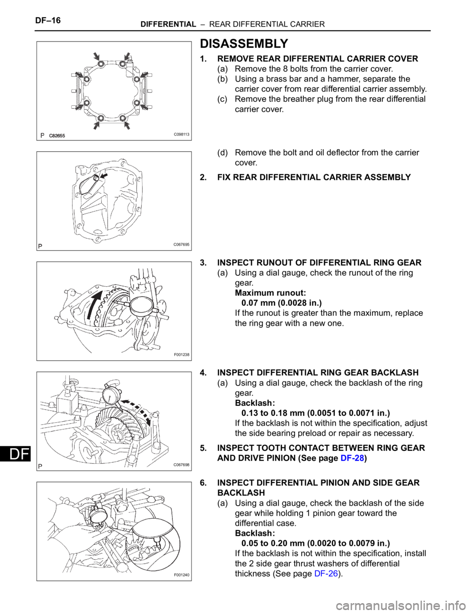
1. REMOVE REAR DIFFERENTIAL CARRIER COVER
(a) Remove the 8 bolts from the carrier cover.
(b) Using a brass bar and a hammer, separate the
carrier cover from rear differential carrier assembly.
(c) Remove the breather plug from the rear differential
carrier cover.
(d) Remove the bolt and oil deflector from the carrier
cover.
2. FIX REAR DIFFERENTIAL CARRIER ASSEMBLY
3. INSPECT RUNOUT OF DIFFERENTIAL RING GEAR
(a) Using a dial gauge, check the runout of the ring
gear.
Maximum runout:
0.07 mm (0.0028 in.)
If the runout is greater than the maximum, replace
the ring gear with a new one.
4. INSPECT DIFFERENTIAL RING GEAR BACKLASH
(a) Using a dial gauge, check the backlash of the ring
gear.
Backlash:
0.13 to 0.18 mm (0.0051 to 0.0071 in.)
If the backlash is not within the specification, adjust
the side bearing preload or repair as necessary.
5. INSPECT TOOTH CONTACT BETWEEN RING GEAR
AND DRIVE PINION (See page DF-28)
6. INSPECT DIFFERENTIAL PINION AND SIDE GEAR
BACKLASH
(a) Using a dial gauge, check the backlash of the side
gear while holding 1 pinion gear toward the
differential case.
Backlash:
0.05 to 0.20 mm (0.0020 to 0.0079 in.)
If the backlash is not within the specification, install
the 2 side gear thrust washers of differential
thickness (See page DF-26).
C098113
C067695
F001238
C067698
F001240