Page 1 of 3000

INTRODUCTION – REPAIR INSTRUCTIONIN–25
IN
VEHICLE LIFT AND SUPPORT
LOCATIONS
1. NOTICE ABOUT VEHICLE CONDITION WHEN
JACKING UP VEHICLE
(a) The vehicle must be unloaded before jacking up/
lifting up the vehicle. Never jack up/lift up a heavily
loaded vehicle.
(b) When removing heavy parts such as the engine and
transmission, the center of gravity of the vehicle
may shift. To stabilize the vehicle, place a balance
weight in a location where it will not roll or shift, or
use a transmission jack to hold the jacking support.
2. NOTICE FOR USING 4 POST LIFT
(a) Follow the safety procedures outlined in the lift
instruction manual.
(b) Use precautionary measures to prevent the free
wheel beam from damaging tires or wheels.
(c) Use wheel chocks to secure the vehicle.
3. NOTICE FOR USING JACK AND SAFETY STAND
(a) Work on a level surface. Use wheel chocks at all
times.
(b) Set the jack and rigid racks to the specified
locations of the vehicle accurately.
(c) When jacking up the vehicle, first release the
parking brake and move the shift lever to N.
(d) When jacking up the entire vehicle:
(1) When jacking up the front wheels first, make
sure wheel chocks are behind the rear wheels.
(2) When jacking up the rear wheels first, make sure
wheel chocks are in front of the front wheels.
(e) When jacking up only the front or rear wheels of the
vehicle:
(1) Before jacking up the front wheels, place wheel
chocks on both sides of the rear wheels.
(2) Before jacking up the rear wheels, place wheel
chocks on both sides of the front wheels.
(f) When lowering a vehicle that only has its front or
rear wheels jacked up:
(1) Before lowering the front wheels, make sure
wheel chocks are in front of the rear wheels.
(2) Before lowering the rear wheels, make sure
wheel chocks are behind the front wheels.
Page 16 of 3000

SS–30SERVICE SPECIFICATIONS – U151E AUTOMATIC TRANSAXLE
SS
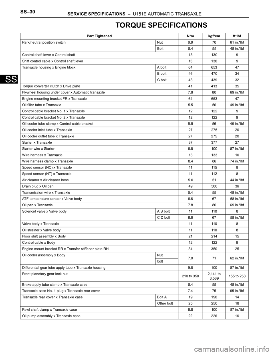
TORQUE SPECIFICATIONS
Part Tightened N*m kgf*cm ft*lbf
Park/neutral position switch Nut 6.9 70 61 in.*lbf
Bolt 5.4 55 48 in.*lbf
Control shaft lever x Control shaft 13 130 9
Shift control cable x Control shaft lever 13 130 9
Transaxle housing x Engine block A bolt 64 653 47
B bolt 46 470 34
C bolt 43 439 32
Torque converter clutch x Drive plate 41 413 35
Flywheel housing under cover x Automatic transaxle 7.8 80 69 in.*lbf
Engine mounting bracket FR x Transaxle 64 653 47
Oil filler tube x Transaxle5.5 56 49 in.*lbf
Control cable bracket No. 1 x Transaxle 12 122 9
Control cable bracket No. 2 x Transaxle 12 122 9
Oil cooler tube clamp x Control cable bracket 5.5 56 49 in.*lbf
Oil cooler inlet tube x Transaxle27 275 20
Oil cooler outlet tube x Transaxle 27 275 20
Starter x Transaxle37 377 27
Starter wire x Starter9.8 100 87 in.*lbf
Wire harness x Transaxle13 133 10
Wire harness clamp x Transaxle8.4 86 74 in.*lbf
Speed sensor (NC) x Transaxle11 11 5 8
Speed sensor (NT) x Transaxle11 11 2 8
Air cleaner x Air cleaner hose5.0 51 44 in.*lbf
Drain plug x Oil pan49 500 36
Transmission wire x Transaxle5.4 55 48 in.*lbf
ATF temperature sensor x Valve body 6.6 67 58 in.*lbf
Oil pan x Transaxle7.8 80 69 in.*lbf
Solenoid valve x Valve body A B bolt 11 110 8
C D bolt 6.6 67 58 in.*lbf
Valve body x Transaxle11 11 0 8
Oil strainer x Valve body11 11 0 8
Floor shift assembly x Body21 214 15
Control cable x Body12 122 9
Engine mount bracket RR x Transfer stiffener plate RH 34 350 25
Oil cooler assembly x Body Nut
7.0 71 62 in.*lbf
bolt
Differential gear lube apply tube x Transaxle housing 9.8 100 87 in.*lbf
Front planetary gear lock nut
210 to 3502,141 to
3,569155 to 258
Brake apply tube clamp x Transaxle case 5.4 55 48 in.*lbf
Transaxle case No. 1 plug x Transaxle rear cover 7.4 75 65 in.*lbf
Transaxle rear cover x Transaxle case Bolt A 19 190 14
Other bolt 25 250 18
Pawl shaft clamp x Transaxle case 9.8 100 87 in.*lbf
Oil pump assembly x Transaxle case 22 226 16
Page 168 of 3000

SUSPENSION – SUSPENSION SYSTEMSP–3
SP
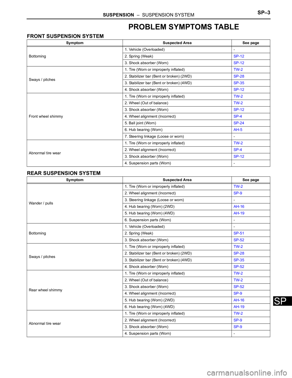
PROBLEM SYMPTOMS TABLE
FRONT SUSPENSION SYSTEM
REAR SUSPENSION SYSTEM
Symptom Suspected Area See page
Bottoming1. Vehicle (Overloaded) -
2. Spring (Weak)SP-12
3. Shock absorber (Worn)SP-12
Sways / pitches1. Tire (Worn or improperly inflated)TW-2
2. Stabilizer bar (Bent or broken) (2WD)SP-28
3. Stabilizer bar (Bent or broken) (4WD)SP-35
4. Shock absorber (Worn)SP-12
Front wheel shimmy1. Tire (Worn or improperly inflated)TW-2
2. Wheel (Out of balance)TW-2
3. Shock absorber (Worn)SP-12
4. Wheel alignment (Incorrect)SP-4
5. Ball joint (Worn)SP-24
6. Hub bearing (Worn)AH-5
7. Steering linkage (Loose or worn) -
Abnormal tire wear1. Tire (Worn or improperly inflated)TW-2
2. Wheel alignment (Incorrect)SP-4
3. Shock absorber (Worn)SP-12
4. Suspension parts (Worn) -
Symptom Suspected Area See page
Wander / pulls1. Tire (Worn or improperly inflated)TW-2
2. Wheel alignment (Incorrect)SP-9
3. Steering linkage (Loose or worn) -
4. Hub bearing (Worn) (2WD)AH-16
5. Hub bearing (Worn) (4WD)AH-19
6. Suspension parts (Worn) -
Bottoming1. Vehicle (Overloaded) -
2. Spring (Weak)SP-51
3. Shock absorber (Worn)SP-52
Sways / pitches1. Tire (Worn or improperly inflated)TW-2
2. Stabilizer bar (Bent or broken) (2WD)SP-28
3. Stabilizer bar (Bent or broken) (4WD)SP-35
4. Shock absorber (Worn)SP-52
Rear wheel shimmy1. Tire (Worn or improperly inflated)TW-2
2. Wheel (Out of balance)TW-2
3. Shock absorber (Worn)SP-52
4. Wheel alignment (Incorrect)SP-9
5. Hub bearing (Worn) (2WD)AH-16
6. Hub bearing (Worn) (4WD)AH-19
Abnormal tire wear1. Tire (Worn or improperly inflated)TW-2
2. Wheel alignment (Incorrect)SP-9
3. Shock absorber (Worn)SP-9
4. Suspension parts (Worn) -
Page 169 of 3000
SUSPENSION – REAR SHOCK ABSORBERSP–51
SP
REMOVAL
1. REMOVE REAR WHEEL
2. REMOVE REAR SHOCK ABSORBER CAP LH
(a) Remove the shock absorber head cover.
(b) Remove the shock absorber cap LH.
3. REMOVE SHOCK ABSORBER ASSEMBLY REAR LH
(a) Support the rear axle beam with a jack.
(b) Using a 6 mm hexagon wrench to hold the piston
rod, remove the lock nut.
(c) Remove the rear shock absorber LH cushion
retainer and rear shock absorber cushion No.1.
G023895
C088670
G023896
G023897
Page 171 of 3000
SUSPENSION – REAR SHOCK ABSORBERSP–53
SP
(d) Install the rear shock absorber cushion No.1 and
rear shock absorber LH cushion retainer.
(e) Temporary tighten a new lock nut.
(f) Using a 6mm hexagon wrench to hold the piston
rod, fully tighten the lock nut.
Torque: 30 N*m (310 kgf*cm, 22 ft.*lbf)
2. INSTALL REAR SHOCK ABSORBER CAP LH
(a) Install the shock absorber cap LH as shown in the
illustration.
(b) Install the shock absorber head cover.
3. INSTALL REAR WHEEL
Torque: 103 N*m (1,050 kgf*cm, 76 ft.*lbf)
G023897
G023896
G024672
G023895
Page 172 of 3000
SP–54SUSPENSION – REAR SHOCK ABSORBER
SP
4. FULLY TIGHTEN SHOCK ABSORBER ASSEMBLY
REAR LH
(a) Stabilize the shock absorber assembly rear LH.
If it is impossible to tighten the nut at this position,
support the rear axle beam with a jack and load the
rear compartment with a mass of approximately 90
kg (198 lb).
Length of shock absorber:
2WD DRIVE TYPE:
234 mm (9.22 in.)
4WD DRIVE TYPE:
258 mm (10.16 in.)
(b) Fully tighten the nut.
Torque: 115 N*m (1,173 kgf*cm, 85 ft.*lbf)
5. INSPECT REAR WHEEL ALIGNMENT
HINT:
(See page SP-9)
DISPOSAL
1. DISPOSE OF SHOCK ABSORBER ASSEMBLY REAR
LH
(a) Fully extend the shock absorber rod.
(b) Using a drill, make a hole in the cylinder as shown in
the illustration to discharge the gas inside the
cylinder.
CAUTION:
• When drilling, since the fragments may fly
out, work carefully.
• The discharged gas is colorless, odorless
and non-poisonous.
C088682
C088671
C066544E01
Page 173 of 3000
TIRE AND WHEEL – TIRE AND WHEEL SYSTEMTW–3
TW
INSPECTION
1. INSPECT TIRES
(a) Check the tires for wear and proper inflation
pressure.
Cold tire inflation pressure
(b) Using a dial indicator, check the runout of the tires.
Tire runout:
1.4 mm (0.055 in.) or less
2. ROTATE TIRES
HINT:
Rotate the tires as shown in the illustration.
3. INSPECT WHEEL BALANCE (for Steel Wheel)
(a) Check and adjust the off-the-car balance.
Imbalance after adjustment:
8.0 g (0.018 lb.) or less.
HINT:
If necessary, check and adjust the on-the-car
balance.
Tire size
Front kPa (kgf*cm2, psi) Rear kPa (kgf*cm2, psi)
P215/65R16 96T
P225/60R17 98T240 (2.4, 35) 240 (2.4, 35)
C137874
C140312E01
C144019
Page 174 of 3000

TW–4TIRE AND WHEEL – TIRE AND WHEEL SYSTEM
TW
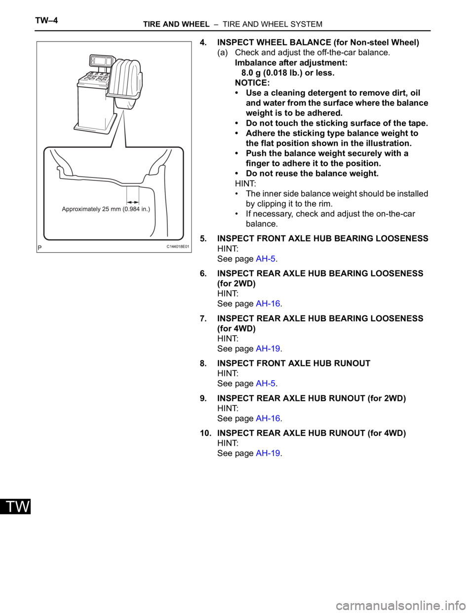
4. INSPECT WHEEL BALANCE (for Non-steel Wheel)
(a) Check and adjust the off-the-car balance.
Imbalance after adjustment:
8.0 g (0.018 lb.) or less.
NOTICE:
• Use a cleaning detergent to remove dirt, oil
and water from the surface where the balance
weight is to be adhered.
• Do not touch the sticking surface of the tape.
• Adhere the sticking type balance weight to
the flat position shown in the illustration.
• Push the balance weight securely with a
finger to adhere it to the position.
• Do not reuse the balance weight.
HINT:
• The inner side balance weight should be installed
by clipping it to the rim.
• If necessary, check and adjust the on-the-car
balance.
5. INSPECT FRONT AXLE HUB BEARING LOOSENESS
HINT:
See page AH-5.
6. INSPECT REAR AXLE HUB BEARING LOOSENESS
(for 2WD)
HINT:
See page AH-16.
7. INSPECT REAR AXLE HUB BEARING LOOSENESS
(for 4WD)
HINT:
See page AH-19.
8. INSPECT FRONT AXLE HUB RUNOUT
HINT:
See page AH-5.
9. INSPECT REAR AXLE HUB RUNOUT (for 2WD)
HINT:
See page AH-16.
10. INSPECT REAR AXLE HUB RUNOUT (for 4WD)
HINT:
See page AH-19.
C144018E01