Page 2113 of 3000
DIFFERENTIAL – REAR DIFFERENTIAL CARRIER ASSEMBLYDF–13
DF
9. FULLY TIGHTEN PROPELLER WITH CENTER
BEARING SHAFT ASSEMBLY (See page PR-10)
10. INSTALL REAR DIFFERENTIAL DRAIN PLUG
(a) Using a hexagon wrench (10 mm), install the drain
plug with a new gasket.
Torque: 49 N*m (500 kgf*cm, 36 ft.*lbf)
11. ADD DIFFERENTIAL OIL
(a) Fill the rear differential carrier assembly with hypoid
gear oil.
12. INSPECT DIFFERENTIAL OIL
HINT:
(See page DF-3)
13. INSTALL REAR DIFFERENTIAL FILLER PLUG
(a) Using a hexagon wrench (10 mm), install the filler
plug with a new gasket.
Torque: 49 N*m (500 kgf*cm, 36 ft.*lbf)
14. INSTALL REAR WHEEL
Torque: 103 N*m (1,050 kgf*cm, 76 ft.*lbf)
15. INSTALL EXHAUST PIPE ASSEMBLY
HINT:
(See page EX-10)
16. INSPECT FOR EXHAUST GAS LEAK
HINT:
(See page EX-12)
17. INSPECT AND ADJUST REAR WHEEL ALIGNMENT
HINT:
(See page SP-4)
18. INSPECT ABS SPEED SENSOR SIGNAL
HINT:
(See page BC-3)
Page 2157 of 3000

AXLE – REAR AXLE HUB BOLTAH–13
AH
REPLACEMENT
HINT:
Replace the RH side using the same procedures as for the
LH side.
1. REMOVE REAR WHEEL
2. SEPARATE REAR DISC BRAKE CALIPER
ASSEMBLY LH
(a) Separate rear disc brake caliper assembly LH for
2WD and disk rear brake type (See page AH-16).
3. SEPARATE REAR DISC BRAKE CALIPER
ASSEMBLY LH
(a) Separate rear disc brake caliper assembly LH for
4WD and disk rear brake type (See page AH-19).
4. REMOVE REAR DISC
(a) Remove rear disc for disk rear brake type.
5. REMOVE REAR BRAKE DRUM SUB-ASSEMBLY
(a) Remove rear brake drum sub-assembly for drum
rear brake type.
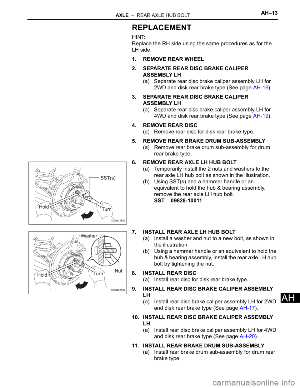
6. REMOVE REAR AXLE LH HUB BOLT
(a) Temporarily install the 2 nuts and washers to the
rear axle LH hub bolt as shown in the illustration.
(b) Using SST(s) and a hammer handle or an
equivalent to hold the hub & bearing assembly,
remove the rear axle LH hub bolt.
SST 09628-10011
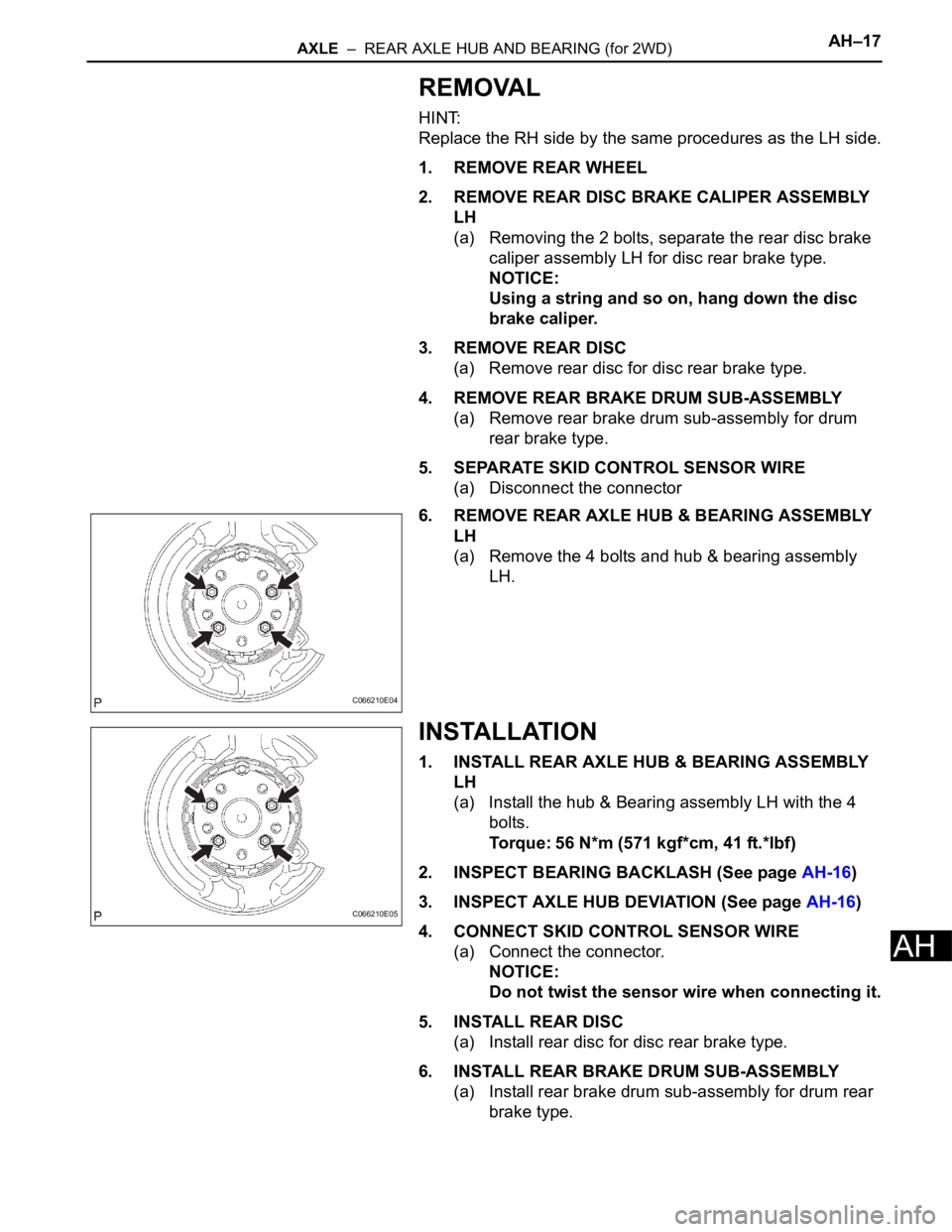
7. INSTALL REAR AXLE LH HUB BOLT
(a) Install a washer and nut to a new bolt, as shown in
the illustration.
(b) Using a hammer handle or an equivalent to hold the
hub & bearing assembly, install the rear axle LH hub
bolt by tightening the nut.
8. INSTALL REAR DISC
(a) Install rear disc for disk rear brake type.
9. INSTALL REAR DISC BRAKE CALIPER ASSEMBLY
LH
(a) Install rear disc brake caliper assembly LH for 2WD
and disk rear brake type (See page AH-17).
10. INSTALL REAR DISC BRAKE CALIPER ASSEMBLY
LH
(a) Install rear disc brake caliper assembly LH for 4WD
and disk rear brake type (See page AH-20).
11. INSTALL REAR BRAKE DRUM SUB-ASSEMBLY
(a) Install rear brake drum sub-assembly for drum rear
brake type.
G026421E02
G026422E02
Page 2158 of 3000
AH–14AXLE – REAR AXLE HUB BOLT
AH
12. INSTALL REAR WHEEL
Torque: 103 N*m (1,050 kgf*cm, 76 ft.*lbf)
Page 2159 of 3000

AXLE – REAR AXLE HUB AND BEARING (for 2WD)AH–17
AH
REMOVAL
HINT:
Replace the RH side by the same procedures as the LH side.
1. REMOVE REAR WHEEL
2. REMOVE REAR DISC BRAKE CALIPER ASSEMBLY
LH
(a) Removing the 2 bolts, separate the rear disc brake
caliper assembly LH for disc rear brake type.
NOTICE:
Using a string and so on, hang down the disc
brake caliper.
3. REMOVE REAR DISC
(a) Remove rear disc for disc rear brake type.
4. REMOVE REAR BRAKE DRUM SUB-ASSEMBLY
(a) Remove rear brake drum sub-assembly for drum
rear brake type.
5. SEPARATE SKID CONTROL SENSOR WIRE
(a) Disconnect the connector
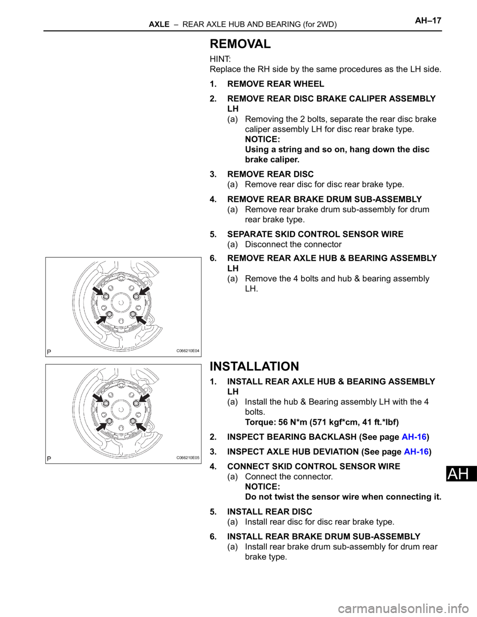
6. REMOVE REAR AXLE HUB & BEARING ASSEMBLY
LH
(a) Remove the 4 bolts and hub & bearing assembly
LH.
INSTALLATION
1. INSTALL REAR AXLE HUB & BEARING ASSEMBLY
LH
(a) Install the hub & Bearing assembly LH with the 4
bolts.
Torque: 56 N*m (571 kgf*cm, 41 ft.*lbf)
2. INSPECT BEARING BACKLASH (See page AH-16)
3. INSPECT AXLE HUB DEVIATION (See page AH-16)
4. CONNECT SKID CONTROL SENSOR WIRE
(a) Connect the connector.
NOTICE:
Do not twist the sensor wire when connecting it.
5. INSTALL REAR DISC
(a) Install rear disc for disc rear brake type.
6. INSTALL REAR BRAKE DRUM SUB-ASSEMBLY
(a) Install rear brake drum sub-assembly for drum rear
brake type.
C066210E04
C066210E05
Page 2160 of 3000
AH–18AXLE – REAR AXLE HUB AND BEARING (for 2WD)
AH
7. INSTALL REAR DISC BRAKE CALIPER ASSEMBLY
LH
(a) Install the rear disc brake caliper assembly LH with
the 2 bolts for disc rear brake type.
Torque: 88 N*m (900 kgf*cm, 65 ft.*lbf)
8. INSTALL REAR WHEEL
Torque: 103 N*m (1,050 kgf*cm, 76 ft.*lbf)
9. CHECK ABS SPEED SENSOR SIGNAL
(a) ABS WITH EBD SYSTEM (See page BC-3).
(b) ABS WITH EBD & BA & TRAC & VSC SYSTEM
(See page BC-72).
Page 2161 of 3000

AH–20AXLE – REAR AXLE HUB AND BEARING (for 4WD)
AH
REMOVAL
HINT:
Replace the RH side by the same procedures as the LH side.
1. REMOVE REAR WHEEL
2. REMOVE REAR AXLE SHAFT LH NUT (See page DS-
22)
3. SEPARATE REAR DISC BRAKE CALIPER
ASSEMBLY LH
(a) Removing the 2 bolts, separate the rear disc brake
caliper assembly LH.
4. REMOVE REAR DISC
5. SEPARATE SPEED SENSOR REAR LH
(a) Removing the bolt, separate the speed sensor rear
LH.
NOTICE:
• Be careful not to damage the speed sensor.
• Prevent foreign matter from attaching to the
speed sensor.
6. REMOVE REAR DRIVE SHAFT ASSEMBLY LH (See
page DS-22)
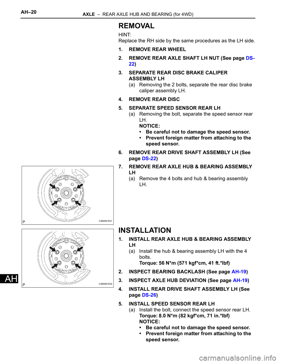
7. REMOVE REAR AXLE HUB & BEARING ASSEMBLY
LH
(a) Remove the 4 bolts and hub & bearing assembly
LH.
INSTALLATION
1. INSTALL REAR AXLE HUB & BEARING ASSEMBLY
LH
(a) Install the hub & bearing assembly LH with the 4
bolts.
Torque: 56 N*m (571 kgf*cm, 41 ft.*lbf)
2. INSPECT BEARING BACKLASH (See page AH-19)
3. INSPECT AXLE HUB DEVIATION (See page AH-19)
4. INSTALL REAR DRIVE SHAFT ASSEMBLY LH (See
page DS-26)
5. INSTALL SPEED SENSOR REAR LH
(a) Install the bolt, connect the speed sensor rear LH.
Torque: 8.0 N*m (82 kgf*cm, 71 in.*lbf)
NOTICE:
• Be careful not to damage the speed sensor.
• Prevent foreign matter from attaching to the
speed sensor.
C065991E01
C065991E02
Page 2162 of 3000
AXLE – REAR AXLE HUB AND BEARING (for 4WD)AH–21
AH
• Do not twist the sensor wire when installing
the sensor.
6. INSTALL REAR DISC
7. INSTALL REAR DISC BRAKE CALIPER ASSEMBLY
LH
(a) Install the rear disc brake caliper assembly LH with
the 2 bolts.
Torque: 88 N*m (900 kgf*cm, 65 ft.*lbf)
8. INSTALL REAR AXLE SHAFT LH NUT (See page DS-
26)
9. INSTALL REAR WHEEL
Torque: 103 N*m (1,050 kgf*cm, 76 ft.*lbf)
10. CHECK ABS SPEED SENSOR SIGNAL
(a) ABS WITH EBD & BA & TRAC & VSC SYSTEM
(See page BC-72).
Page 2172 of 3000

AXLE – REAR AXLE HUB AND BEARING (for 2WD)AH–17
AH
REMOVAL
HINT:
Replace the RH side by the same procedures as the LH side.
1. REMOVE REAR WHEEL
2. REMOVE REAR DISC BRAKE CALIPER ASSEMBLY
LH
(a) Removing the 2 bolts, separate the rear disc brake
caliper assembly LH for disc rear brake type.
NOTICE:
Using a string and so on, hang down the disc
brake caliper.
3. REMOVE REAR DISC
(a) Remove rear disc for disc rear brake type.
4. REMOVE REAR BRAKE DRUM SUB-ASSEMBLY
(a) Remove rear brake drum sub-assembly for drum
rear brake type.
5. SEPARATE SKID CONTROL SENSOR WIRE
(a) Disconnect the connector
6. REMOVE REAR AXLE HUB & BEARING ASSEMBLY
LH
(a) Remove the 4 bolts and hub & bearing assembly
LH.
INSTALLATION
1. INSTALL REAR AXLE HUB & BEARING ASSEMBLY
LH
(a) Install the hub & Bearing assembly LH with the 4
bolts.
Torque: 56 N*m (571 kgf*cm, 41 ft.*lbf)
2. INSPECT BEARING BACKLASH (See page AH-16)
3. INSPECT AXLE HUB DEVIATION (See page AH-16)
4. CONNECT SKID CONTROL SENSOR WIRE
(a) Connect the connector.
NOTICE:
Do not twist the sensor wire when connecting it.
5. INSTALL REAR DISC
(a) Install rear disc for disc rear brake type.
6. INSTALL REAR BRAKE DRUM SUB-ASSEMBLY
(a) Install rear brake drum sub-assembly for drum rear
brake type.
C066210E04
C066210E05