2007 TOYOTA SIENNA lower control arm
[x] Cancel search: lower control armPage 329 of 3000

2GR-FE ENGINE CONTROL SYSTEM – SFI SYSTEMES–261
ES
1. A/F CONTROL
HINT:
Intelligent tester only:
Malfunctioning areas can be identified by performing the A/F CONTROL function provided in the
ACTIVE TEST. The A/F CONTROL function can help to determine whether the Air-Fuel Ratio (A/F)
sensor, Heated Oxygen (HO2) sensor and other potential trouble areas are malfunctioning.
The following instructions describe how to conduct the A/F CONTROL operation using an intelligent
tester.
(a) Connect the intelligent tester to the DLC3.
(b) Start the engine and turn the tester on.
(c) Warm up the engine at an engine speed of 2500 rpm for approximately 90 seconds.
(d) On the tester, select the following menu items: DIAGNOSIS / ENHANCED OBD II / ACTIVE
TEST / A/F CONTROL.
(e) Perform the A/F CONTROL operation with the engine in an idling condition (press the RIGHT or
LEFT button to change the fuel injection volume).
(f) Monitor the voltage outputs of the A/F and HO2 sensors (AFS B1S1 and O2S B1S2 or AFS
B2S1 and O2S B2S2) displayed on the tester.
HINT:
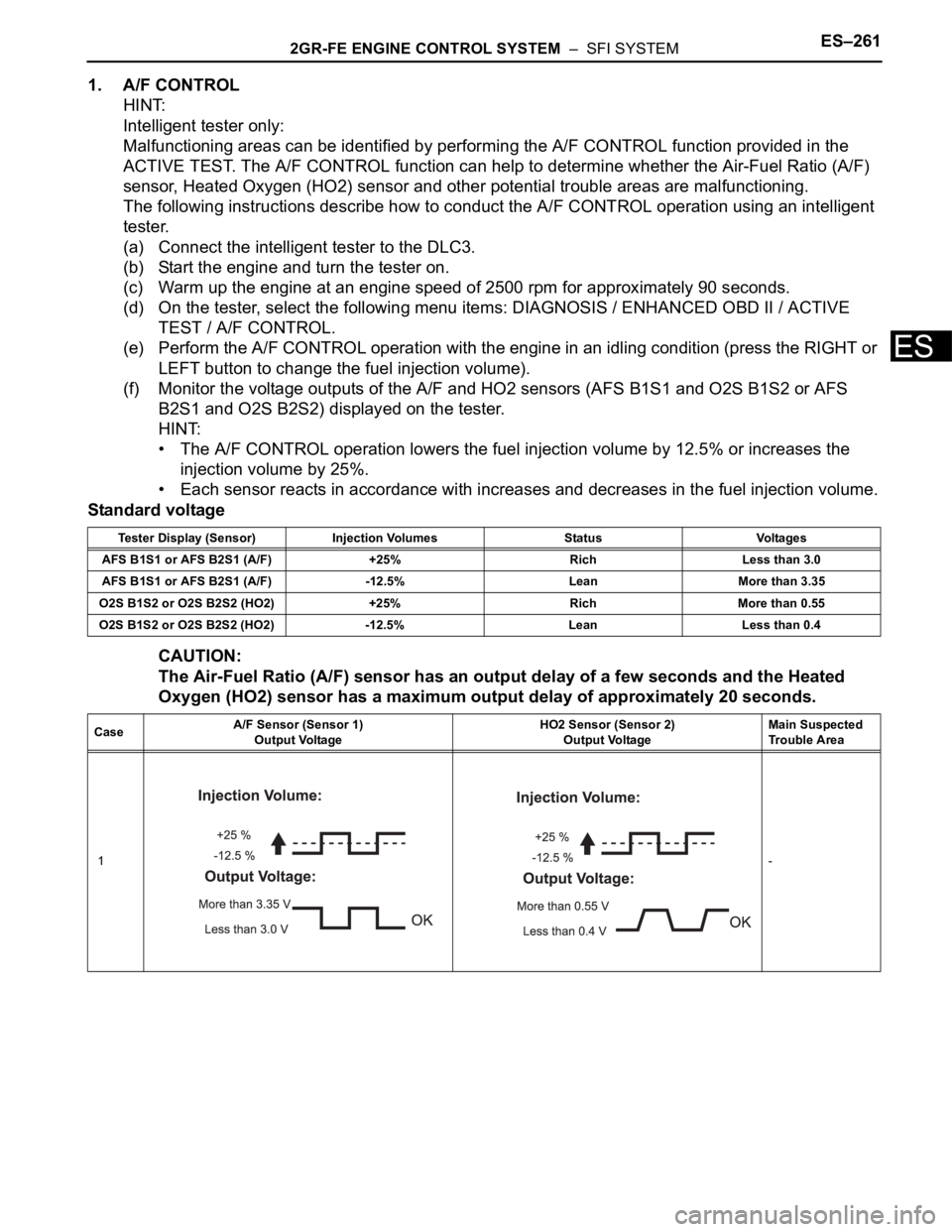
• The A/F CONTROL operation lowers the fuel injection volume by 12.5% or increases the
injection volume by 25%.
• Each sensor reacts in accordance with increases and decreases in the fuel injection volume.
Standard voltage
CAUTION:
The Air-Fuel Ratio (A/F) sensor has an output delay of a few seconds and the Heated
Oxygen (HO2) sensor has a maximum output delay of approximately 20 seconds.
Tester Display (Sensor) Injection Volumes Status Voltages
AFS B1S1 or AFS B2S1 (A/F) +25% Rich Less than 3.0
AFS B1S1 or AFS B2S1 (A/F) -12.5% Lean More than 3.35
O2S B1S2 or O2S B2S2 (HO2) +25% Rich More than 0.55
O2S B1S2 or O2S B2S2 (HO2) -12.5% Lean Less than 0.4
CaseA/F Sensor (Sensor 1)
Output VoltageHO2 Sensor (Sensor 2)
Output VoltageMain Suspected
Trouble Area
1-
Page 331 of 3000

2GR-FE ENGINE CONTROL SYSTEM – SFI SYSTEMES–263
ES
(b) Turn the ignition switch to the ON position and turn the
tester on.
(c) Select the following menu items: DIAGNOSIS /
ENHANCED OBD II / DTC INFO / CURRENT CODES.
(d) Read the DTCs.
Result
HINT:
If any DTCs other than P0420 or P0430 are output,
troubleshoot those DTCs first.
B
A
(a) Connect the intelligent tester to the DLC3.
(b) Start the engine and turn the tester on.
(c) Warm up the engine at an engine speed of 2500 rpm for
approximately 90 seconds.
(d) Select the following menu items on the tester:
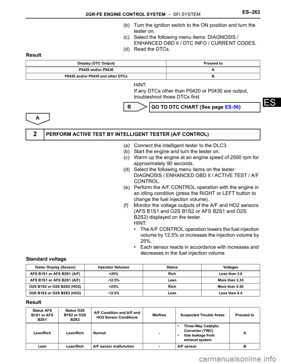
DIAGNOSIS / ENHANCED OBD II / ACTIVE TEST / A/F
CONTROL.
(e) Perform the A/F CONTROL operation with the engine in
an idling condition (press the RIGHT or LEFT button to
change the fuel injection volume).
(f) Monitor the voltage outputs of the A/F and HO2 sensors
(AFS B1S1 and O2S B1S2 or AFS B2S1 and O2S
B2S2) displayed on the tester.
HINT:
• The A/F CONTROL operation lowers the fuel injection
volume by 12.5% or increases the injection volume by
25%.
• Each sensor reacts in accordance with increases and
decreases in the fuel injection volume.
Standard voltage
Result
Display (DTC Output) Proceed to
P0420 and/or P0430 A
P0420 and/or P0430 and other DTCs B
GO TO DTC CHART (See page ES-56)
2PERFORM ACTIVE TEST BY INTELLIGENT TESTER (A/F CONTROL)
Tester Display (Sensor) Injection Volumes Status Voltages
AFS B1S1 or AFS B2S1 (A/F) +25% Rich Less than 3.0
AFS B1S1 or AFS B2S1 (A/F) -12.5% Lean More than 3.35
O2S B1S2 or O2S B2S2 (HO2) +25% Rich More than 0.55
O2S B1S2 or O2S B2S2 (HO2) -12.5% Lean Less than 0.4
Status AFS
B1S1 or AFS
B2S1Status O2S
B1S2 or O2S
B2S2A/F Condition and A/F and
HO2 Sensor ConditionsMisfires Suspected Trouble Areas Proceed to
Lean/Rich Lean/Rich Normal -• Three-Way Catalytic
Converter (TWC)
• Gas leakage from
exhaust systemA
Lean Lean/Rich A/F sensor malfunction - A/F sensor B
Page 453 of 3000

2GR-FE ENGINE CONTROL SYSTEM – SFI SYSTEMES–147
ES
DESCRIPTION
Refer to DTC P0115 (See page ES-133).
MONITOR DESCRIPTION
The ECT sensor is used to monitor the ECT. The ECT sensor has a built-in thermistor with a resistance
that varies according to the temperature of the engine coolant. When the ECT becomes low, the
resistance of the thermistor increases. When the temperature becomes high, the resistance drops. These
variations in the resistance are reflected in the voltage output from the ECT sensor.
The ECM monitors the sensor voltage and uses this value to calculate the ECT. If the sensor voltage
output deviates from the normal operating range, the ECM interprets this deviation as a malfunction in the
ECT sensor and sets the DTC.
Examples:
• Upon starting the engine, the ECT is between 35
C and 60C (95F and 140F). If the ECT remains
within 3
C (5.4F) of the stating temperature after driving for 250 seconds, the DTC is set (2 trip
detection logic).
• Upon starting the engine, the ECT is over 60
C (140F). If the ECT remains within 1C (1.8F) of the
starting temperature after driving for 250 seconds, the DTC is set (6 trip detection logic).
MONITOR STRATEGY
DTC P0116Engine Coolant Temperature Circuit Range /
Performance Problem
DTC No. DTC Detection Condition Trouble Area
P0116ECTs as listed below are nearly same (2 trip detection
logic):
– ECT when engine is started at lower than 60
C
(140
F) of ECT
– ECT when engine is warmed up
•Thermostat
• ECT sensor ECTs as listed below are nearly same when engine is
started at higher than 60
C (140F) of ECT (2 trip
detection logic)
– ECT when engine is stopped after driving
– ECT when engine is started at lower than 60
C
(140F) of ECT
When either of following conditions is met (2 trip
detection logic):
• When cold engine started and engine warmed up,
Engine Coolant Temperature (ECT) sensor value
does not change
• After engine is warmed up, ECT sensor value does
not change when engine stopped and then next
cold engine start is performed
Related DTCsP0116: Engine coolant temperature sensor output stuck at low engine coolant
temperature
P0116: Engine coolant temperature sensor output stuck at high engine coolant
temperature
Required Sensors / Components (Main) Engine Coolant Temperature (ECT) sensor
Required Sensors / Components (Related) Crankshaft position sensor, intake air temperature sensor and mass air flow meter
Frequency of Operation Continuous
Duration 5 hours
MIL Operation 2 driving cycles
Sequence of Operation None
Page 483 of 3000

2GR-FE ENGINE CONTROL SYSTEM – SFI SYSTEMES–177
ES
INSPECTION PROCEDURE
HINT:
For use of the intelligent tester only:
Malfunctioning areas can be identified by performing the A/F CONTROL function provided in the ACTIVE
TEST. The A/F CONTROL function can help to determine whether the Air-Fuel Ratio (A/F) sensor, Heated
Oxygen (HO2) sensor and other potential trouble areas are malfunctioning.
The following instructions describe how to conduct the A/F CONTROL operation using the intelligent
tester.
1. Connect the intelligent tester to the DLC3.
2. Start the engine and turn the tester on.
3. Warm up the engine at an engine speed of 2500 rpm for approximately 90 seconds.
4. Select the following menu items on the tester: DIAGNOSIS / ENHANCED OBD II / ACTIVE TEST / A/F
CONTROL.
5. Perform the A/F CONTROL operation with the engine in an idling condition (press the RIGHT or LEFT
button to change the fuel injection volume).
6. Monitor the voltage outputs of the A/F and HO2 sensors (AFS B1S1 and O2S B1S2 or AFS B2S1 and
O2S B2S2) displayed on the tester.
HINT:
• The A/F CONTROL operation lowers the fuel injection volume by 12.5% or increases the injection
volume by 25%.
• Each sensor reacts in accordance with increases and decreases in the fuel injection volume.
Standard voltage
NOTICE:
The Air-Fuel Ratio (A/F) sensor has an output delay of a few seconds and the Heated Oxygen
(HO2) sensor has a maximum output delay of approximately 20 seconds.
Tester Display (Sensor) Injection Volumes Status Voltages
AFS B1S1 or AFS B2S1 (A/F) +25% Rich Less than 3.0
AFS B1S1 or AFS B2S1 (A/F) -12.5% Lean More than 3.35
O2S B1S2 or O2S B2S2 (HO2) +25% Rich More than 0.55
O2S B1S2 or O2S B2S2 (HO2) -12.5% Lean Less than 0.4
CaseA/F Sensor (Sensor 1)
Output VoltageHO2 Sensor (Sensor 2)
Output VoltageMain Suspected
Trouble Area
1-
Page 496 of 3000

ES–1902GR-FE ENGINE CONTROL SYSTEM – SFI SYSTEM
ES
TYPICAL ENABLING CONDITIONS
Fuel-trim:
TYPICAL MALFUNCTION THRESHOLDS
Fuel trim:
WIRING DIAGRAM
Refer to DTC P2195 (See page ES-359).
INSPECTION PROCEDURE
HINT:
For use of the intelligent tester only:
Malfunctioning areas can be identified by performing the A/F CONTROL function provided in the ACTIVE
TEST. The A/F CONTROL function can help to determine whether the Air-Fuel Ratio (A/F) sensor, Heated
Oxygen (HO2) sensor and other potential trouble areas are malfunctioning.
The following instructions describe how to conduct the A/F CONTROL operation using the intelligent
tester.
1. Connect the intelligent tester to the DLC3.
2. Start the engine and turn the tester on.
3. Warm up the engine at an engine speed of 2500 rpm for approximately 90 seconds.
4. Select the following menu items on the tester: DIAGNOSIS / ENHANCED OBD II / ACTIVE TEST / A/F
CONTROL.
5. Perform the A/F CONTROL operation with the engine in an idling condition (press the RIGHT or LEFT
button to change the fuel injection volume).
6. Monitor the voltage outputs of the A/F and HO2 sensors (AFS B1S1 and O2S B1S2 or AFS B2S1 and
O2S B2S2) displayed on the tester.
HINT:
• The A/F CONTROL operation lowers the fuel injection volume by 12.5% or increases the injection
volume by 25%.
• Each sensor reacts in accordance with increases and decreases in the fuel injection volume.
Standard voltage
The monitor will run whenever these DTCs are not
presentP0010, P0020 (VVT VSV1, 2), P0011, P0012 (VVT System-Advance, Retard),
P0021, P0022 (VVT System 2-Adavance, Retard), P0031, P0032, P0051, P0052 (A/
F Sensor Heater Sensor 1), P0100, P0101, P0102, P0103 (MAF Sensor), P0115,
P0116, P0117, P0118 (ECT Sensor), P0120, P0121, P0122, P0123, P0220, P0222,
P0223, P2135 (TP Sensor), P0125 (Insufficient ECT for Closed Loop), P0335 (CKP
Sensor), P0340 (CMP Sensor), P0351, P0352, P0353, P0354, P0356 (Ignitor),
P0500 (VSS)
Fuel system status Closed-loop
Battery voltage 11 V or more
Either of the following conditions is met Condition 1 or 2
1. Engine RPM Less than 1100 rpm
2. Intake air amount per revolution 0.22 g/rev or more
Catalyst monitor Not executed
EVAP purge-cut Executing
Either of the following conditions is met Condition 1 or 2
1. Average between short-term fuel trim and long-term
fuel trim35% or more at 80
C (176F) of ECT
2. Average between short-term fuel trim and long-term
fuel trim-35% or less at 80
C (176F) of ECT
Tester Display (Sensor) Injection Volumes Status Voltages
AFS B1S1 or AFS B2S1 (A/F) +25% Rich Less than 3.0
Page 499 of 3000

2GR-FE ENGINE CONTROL SYSTEM – SFI SYSTEMES–193
ES
OK
(a) Connect the intelligent tester to the DLC3.
(b) Start the engine and turn the tester on.
(c) Warm up the engine at an engine speed of 2500 rpm for
approximately 90 seconds.
(d) Select the following menu items on the tester:
DIAGNOSIS / ENHANCED OBD II / ACTIVE TEST / A/F
CONTROL.
(e) Perform the A/F CONTROL operation with the engine in
an idling condition (press the RIGHT or LEFT button to
change the fuel injection volume).
(f) Monitor the voltage outputs of the A/F and HO2 sensors
(AFS B1S1 and O2S B1S2 or AFS B2S1 and O2S
B2S2) displayed on the tester.
HINT:
• The A/F CONTROL operation lowers the fuel injection
volume by 12.5% or increases the injection volume by
25%.
• Each sensor reacts in accordance with increases and
decreases in the fuel injection volume.
Standard voltage
Result
4PERFORM ACTIVE TEST BY INTELLIGENT TESTER (A/F CONTROL)
Tester Display (Sensor) Injection Volumes Status Voltages
AFS B1S1 or AFS B2S1 (A/F) +25% Rich Less than 3.0
AFS B1S1 or AFS B2S1 (A/F) -12.5% Lean More than 3.35
O2S B1S2 or O2S B2S2 (HO2) +25% Rich More than 0.55
O2S B1S2 or O2S B2S2 (HO2) -12.5% Lean Less than 0.4
Status AFS
B1S1 or AFS
B2S1Status O2S
B1S2 or O2S
B2S2A/F Condition and A/F
Sensor ConditionMisfires Suspected Trouble Areas Proceed to
Lean/Rich Lean/Rich Normal - - C
Lean Lean Actual air-fuel ratio lean May occur• PCV valve and hose
• PCV hose connections
• Injector blockage
• Gas leakage from
exhaust system
• Air induction system
• Fuel pressure
• Mass Air Flow (MAF)
meter
• Engine Coolant
Temperature (ECT)
sensorA
Rich Rich Actual air-fuel ratio rich -• Injector leakage or
blockage
• Gas leakage from
exhaust system
• Ignition system
• Fuel pressure
• MAF meter
• ECT sensorA
Lean Lean/Rich A/F sensor malfunction - A/F sensor B
Rich Lean/Rich A/F sensor malfunction - A/F sensor B
Page 537 of 3000

2GR-FE ENGINE CONTROL SYSTEM – SFI SYSTEMES–231
ES
INSPECTION PROCEDURE
HINT:
• If no problem is found by this diagnostic troubleshooting procedure, troubleshoot the engine
mechanical systems.
• Check the engine speed. The engine speed can be checked by using the intelligent tester. Perform the
following procedure:
(a) Connect the intelligent tester to the DLC3.
(b) Start the engine.
(c) Turn the tester on.
(d) Select the following menu items: DIAGNOSIS / ENHANCED OBD II / DATA LIST / PRIMARY /
ENGINE SPD.
The engine speed may be indicated as zero despite the engine revolving normally. This is caused
by a lack of NE signals from the Crankshaft Position (CKP) sensor. Alternatively, the engine speed
may be indicated as lower than the actual engine speed, if the CKP sensor voltage output is
insufficient.
• Read freeze frame data using the intelligent tester. The ECM records vehicle and driving condition
information as freeze frame data the moment a DTC is stored. When troubleshooting, freeze frame
data can be helpful in determining whether the vehicle was running or stopped, whether the engine
was warmed up or not, whether the air-fuel ratio was lean or rich, as well as other data recorded at the
time of a malfunction.
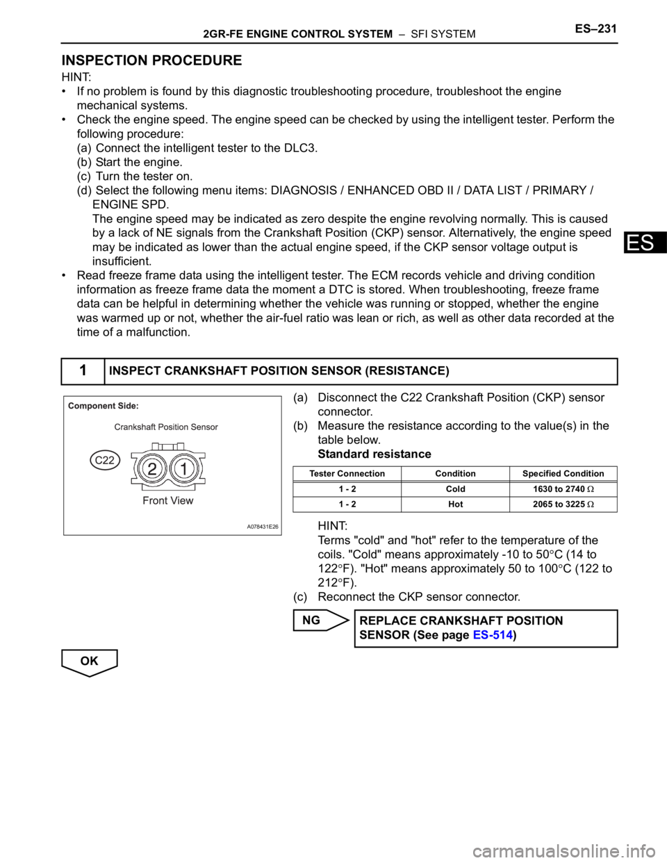
(a) Disconnect the C22 Crankshaft Position (CKP) sensor
connector.
(b) Measure the resistance according to the value(s) in the
table below.
Standard resistance
HINT:
Terms "cold" and "hot" refer to the temperature of the
coils. "Cold" means approximately -10 to 50
C (14 to
122
F). "Hot" means approximately 50 to 100C (122 to
212
F).
(c) Reconnect the CKP sensor connector.
NG
OK
1INSPECT CRANKSHAFT POSITION SENSOR (RESISTANCE)
A078431E26
Tester Connection Condition Specified Condition
1 - 2 Cold 1630 to 2740
1 - 2 Hot 2065 to 3225
REPLACE CRANKSHAFT POSITION
SENSOR (See page ES-514)
Page 597 of 3000

ES–3042GR-FE ENGINE CONTROL SYSTEM – SFI SYSTEM
ES
DESCRIPTION
This monitor will run when the engine is started at -10 to 50C (14 to 122F) of the engine coolant
temperature. The DTC will set after the engine idling for 13 seconds (2 trip detection logic).
The DTC is designed to monitor the idle air control at cold start. When the engine is started at lower than
50
C (122F) of the engine coolant temperature, the ECM measures the accumulated mass air flow at the
engine idling. If it does not reach the criteria within 10 seconds, the ECM interprets this as a malfunction.
The MIL is illuminated and a DTC is set when the malfunction is detected in consecutive driving cycles (2
trip detection logic).
The ETCS (Electrical Throttle Control System) controls the idle speed. The ETCS operates the throttle
actuator to open and close the throttle valve, and adjusts the intake air amount to achieve the target idle
speed.
NOTICE:
When the negative battery terminal is disconnected during inspection or repairs, the ISC (Idle
Speed Control) learned values are cleared. ISC learning is performed when the engine has been
warmed up and idled for 5 minutes because this DTC cannot be set after the ISC learned values
cleared.
DTC P050A Cold Start Idle Air Control System Performance
DTC No. DTC Detection Condition Trouble Area
P050AAccumulated intake air amount for 10 seconds of idling after
cold start is less than threshold (2 trip detection logic)• Throttle body assembly
• Mass air flow meter
• Intake system
• PCV hose connections
• VVT system
• Air cleaner filter element
•ECM