Page 2662 of 3000

PB–10PARKING BRAKE – PARKING BRAKE CABLE
PB
REMOVAL
HINT:
For the parking brake cable assembly No. 2, perform the
same procedure to the parking brake cable assembly No. 3.
1. REMOVE REAR WHEEL
2. REMOVE REAR BRAKE DRUM SUB-ASSEMBLY (for
Drum Type) (See page BR-37)
3. REMOVE FRONT BRAKE SHOE (for Drum Type) (See
page BR-37)
4. REMOVE REAR BRAKE SHOE (for Drum Type) (See
page BR-38)
5. SEPARATE REAR DISC BRAKE CALIPER
ASSEMBLY LH (for Disc Type) (See page PB-15)
6. REMOVE REAR DISC (for Disc Type) (See page BR-
32)
7. REMOVE PARKING BRAKE SHOE ASSEMBLY LH
NO.1 (for Disc Type) (See page PB-15)
8. REMOVE PARKING BRAKE SHOE ADJUSTING
SCREW SET (for Disc Type)
9. REMOVE PARKING BRAKE SHOE STRUT LH (for
Disc Type)
10. REMOVE PARKING BRAKE SHOE ASSEMBLY LH
NO.2 (for Disc Type) (See page PB-15)
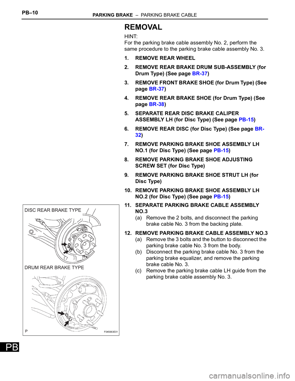
11. SEPARATE PARKING BRAKE CABLE ASSEMBLY
NO.3
(a) Remove the 2 bolts, and disconnect the parking
brake cable No. 3 from the backing plate.
12. REMOVE PARKING BRAKE CABLE ASSEMBLY NO.3
(a) Remove the 3 bolts and the button to disconnect the
parking brake cable No. 3 from the body.
(b) Disconnect the parking brake cable No. 3 from the
parking brake equalizer, and remove the parking
brake cable No. 3.
(c) Remove the parking brake cable LH guide from the
parking brake cable assembly No. 3.
F045063E01
Page 2665 of 3000

PARKING BRAKE – PARKING BRAKE ASSEMBLYPB–15
PB
DISASSEMBLY
HINT:
Overhaul the RH side by the same procedures as these of
the LH side.
1. REMOVE REAR WHEEL
2. SEPARATE REAR DISC BRAKE CALIPER
ASSEMBLY LH
HINT:
Do not disconnect the flexible hose from the brake
caliper.
3. REMOVE REAR DISC
(a) Release the parking brake, and remove the rear
disc.
HINT:
• Align matchmarks on the disc and the axle hub.
• If the disc cannot be removed easily, turn the
shoe adjuster until the wheel turns freely.
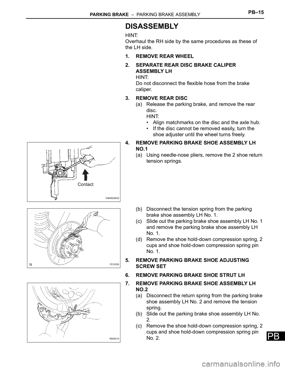
4. REMOVE PARKING BRAKE SHOE ASSEMBLY LH
NO.1
(a) Using needle-nose pliers, remove the 2 shoe return
tension springs.
(b) Disconnect the tension spring from the parking
brake shoe assembly LH No. 1.
(c) Slide out the parking brake shoe assembly LH No. 1
and remove the parking brake shoe assembly LH
No. 1.
(d) Remove the shoe hold-down compression spring, 2
cups and shoe hold-down compression spring pin
No. 1.
5. REMOVE PARKING BRAKE SHOE ADJUSTING
SCREW SET
6. REMOVE PARKING BRAKE SHOE STRUT LH
7. REMOVE PARKING BRAKE SHOE ASSEMBLY LH
NO.2
(a) Disconnect the return spring from the parking brake
shoe assembly LH No. 2 and remove the tension
spring.
(b) Slide out the parking brake shoe assembly LH No.
2.
(c) Remove the shoe hold-down compression spring, 2
cups and shoe hold-down compression spring pin
No. 2.
C064523E02
F012039
R000310
Page 2691 of 3000

PS–20POWER STEERING – VANE PUMP
PS
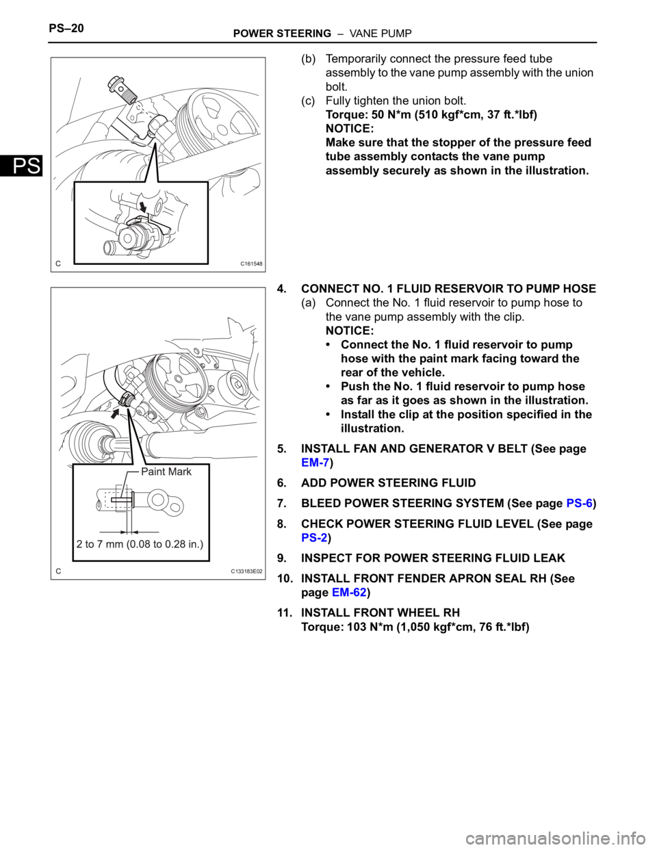
(b) Temporarily connect the pressure feed tube
assembly to the vane pump assembly with the union
bolt.
(c) Fully tighten the union bolt.
Torque: 50 N*m (510 kgf*cm, 37 ft.*lbf)
NOTICE:
Make sure that the stopper of the pressure feed
tube assembly contacts the vane pump
assembly securely as shown in the illustration.
4. CONNECT NO. 1 FLUID RESERVOIR TO PUMP HOSE
(a) Connect the No. 1 fluid reservoir to pump hose to
the vane pump assembly with the clip.
NOTICE:
• Connect the No. 1 fluid reservoir to pump
hose with the paint mark facing toward the
rear of the vehicle.
• Push the No. 1 fluid reservoir to pump hose
as far as it goes as shown in the illustration.
• Install the clip at the position specified in the
illustration.
5. INSTALL FAN AND GENERATOR V BELT (See page
EM-7)
6. ADD POWER STEERING FLUID
7. BLEED POWER STEERING SYSTEM (See page PS-6)
8. CHECK POWER STEERING FLUID LEVEL (See page
PS-2)
9. INSPECT FOR POWER STEERING FLUID LEAK
10. INSTALL FRONT FENDER APRON SEAL RH (See
page EM-62)
11. INSTALL FRONT WHEEL RH
Torque: 103 N*m (1,050 kgf*cm, 76 ft.*lbf)
C161548
C133183E02
Page 2731 of 3000

PS–20POWER STEERING – VANE PUMP
PS
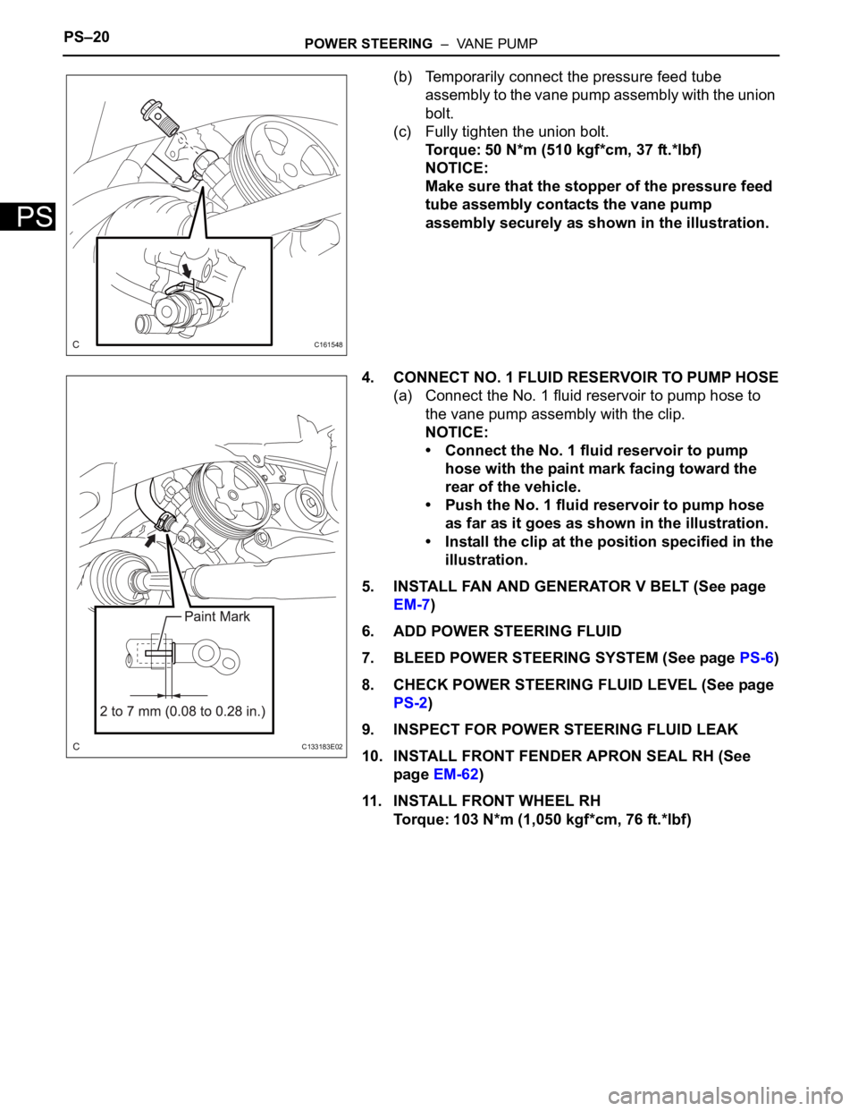
(b) Temporarily connect the pressure feed tube
assembly to the vane pump assembly with the union
bolt.
(c) Fully tighten the union bolt.
Torque: 50 N*m (510 kgf*cm, 37 ft.*lbf)
NOTICE:
Make sure that the stopper of the pressure feed
tube assembly contacts the vane pump
assembly securely as shown in the illustration.
4. CONNECT NO. 1 FLUID RESERVOIR TO PUMP HOSE
(a) Connect the No. 1 fluid reservoir to pump hose to
the vane pump assembly with the clip.
NOTICE:
• Connect the No. 1 fluid reservoir to pump
hose with the paint mark facing toward the
rear of the vehicle.
• Push the No. 1 fluid reservoir to pump hose
as far as it goes as shown in the illustration.
• Install the clip at the position specified in the
illustration.
5. INSTALL FAN AND GENERATOR V BELT (See page
EM-7)
6. ADD POWER STEERING FLUID
7. BLEED POWER STEERING SYSTEM (See page PS-6)
8. CHECK POWER STEERING FLUID LEVEL (See page
PS-2)
9. INSPECT FOR POWER STEERING FLUID LEAK
10. INSTALL FRONT FENDER APRON SEAL RH (See
page EM-62)
11. INSTALL FRONT WHEEL RH
Torque: 103 N*m (1,050 kgf*cm, 76 ft.*lbf)
C161548
C133183E02