Page 2639 of 3000
BRAKE – REAR DRUM BRAKEBR–39
BR
INSPECTION
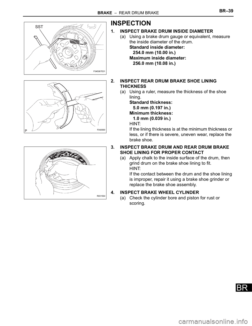
1. INSPECT BRAKE DRUM INSIDE DIAMETER
(a) Using a brake drum gauge or equivalent, measure
the inside diameter of the drum.
Standard inside diameter:
254.0 mm (10.00 in.)
Maximum inside diameter:
256.0 mm (10.08 in.)
2. INSPECT REAR DRUM BRAKE SHOE LINING
THICKNESS
(a) Using a ruler, measure the thickness of the shoe
lining.
Standard thickness:
5.0 mm (0.197 in.)
Minimum thickness:
1.0 mm (0.039 in.)
HINT:
If the lining thickness is at the minimum thickness or
less, or if there is severe, uneven wear, replace the
brake shoe.
3. INSPECT BRAKE DRUM AND REAR DRUM BRAKE
SHOE LINING FOR PROPER CONTACT
(a) Apply chalk to the inside surface of the drum, then
grind drum on the brake shoe lining to fit.
HINT:
If the contact between the drum and the shoe lining
is improper, repair it using a brake shoe grinder or
replace the brake shoe assembly.
4. INSPECT BRAKE WHEEL CYLINDER
(a) Check the cylinder bore and piston for rust or
scoring.
F045067E01
F042690
R001564
Page 2640 of 3000
BR–40BRAKE – REAR DRUM BRAKE
BR
REASSEMBLY
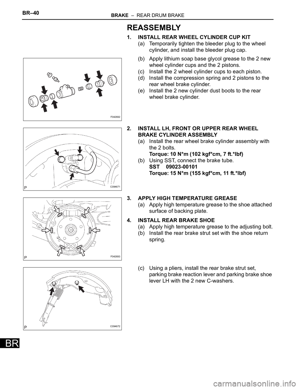
1. INSTALL REAR WHEEL CYLINDER CUP KIT
(a) Temporarily tighten the bleeder plug to the wheel
cylinder, and install the bleeder plug cap.
(b) Apply lithium soap base glycol grease to the 2 new
wheel cylinder cups and the 2 pistons.
(c) Install the 2 wheel cylinder cups to each piston.
(d) Install the compression spring and 2 pistons to the
rear wheel brake cylinder.
(e) Install the 2 new cylinder dust boots to the rear
wheel brake cylinder.
2. INSTALL LH, FRONT OR UPPER REAR WHEEL
BRAKE CYLINDER ASSEMBLY
(a) Install the rear wheel brake cylinder assembly with
the 2 bolts.
Torque: 10 N*m (102 kgf*cm, 7 ft.*lbf)
(b) Using SST, connect the brake tube.
SST 09023-00101
Torque: 15 N*m (155 kgf*cm, 11 ft.*lbf)
3. APPLY HIGH TEMPERATURE GREASE
(a) Apply high temperature grease to the shoe attached
surface of backing plate.
4. INSTALL REAR BRAKE SHOE
(a) Apply high temperature grease to the adjusting bolt.
(b) Install the rear brake strut set with the shoe return
spring.
(c) Using a pliers, install the rear brake strut set,
parking brake reaction lever and parking brake shoe
lever LH with the 2 new C-washers.
F042692
C094671
F042693
C094672
Page 2643 of 3000
BRAKE – REAR DRUM BRAKEBR–43
BR
(c) Using a screwdriver, back off the adjuster 15
notches.
(d) Install the hole plug.
9. FILL RESERVOIR WITH BRAKE FLUID (See page BR-
3)
10. BLEED BRAKE MASTER CYLINDER (See page BR-3)
11. BLEED BRAKE LINE (See page BR-4)
12. BLEED BRAKE ACTUATOR (w/ VSC) (See page BR-
4)
13. CHECK FLUID LEVEL IN RESERVOIR (See page BR-
7)
14. CHECK BRAKE FLUID LEAKAGE
15. INSTALL REAR WHEEL
Torque: 103 N*m (,050 kgf*cm, 76 ft.*lbf)
16. INSPECT PARKING BRAKE PEDAL TRAVEL
17. ADJUST PARKING BRAKE PEDAL TRAVEL
F040023E05
Page 2644 of 3000
BRAKE – REAR DRUM BRAKEBR–39
BR
INSPECTION
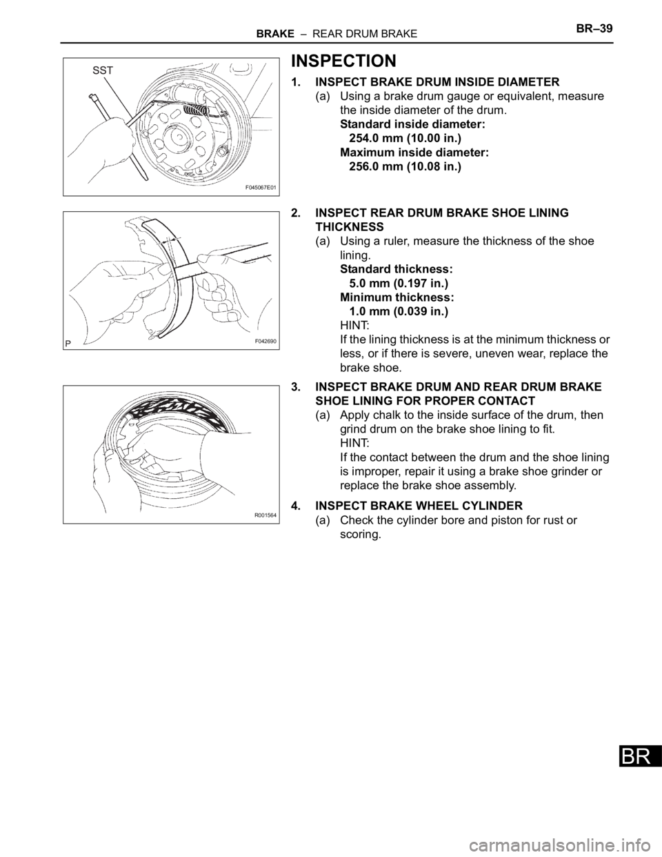
1. INSPECT BRAKE DRUM INSIDE DIAMETER
(a) Using a brake drum gauge or equivalent, measure
the inside diameter of the drum.
Standard inside diameter:
254.0 mm (10.00 in.)
Maximum inside diameter:
256.0 mm (10.08 in.)
2. INSPECT REAR DRUM BRAKE SHOE LINING
THICKNESS
(a) Using a ruler, measure the thickness of the shoe
lining.
Standard thickness:
5.0 mm (0.197 in.)
Minimum thickness:
1.0 mm (0.039 in.)
HINT:
If the lining thickness is at the minimum thickness or
less, or if there is severe, uneven wear, replace the
brake shoe.
3. INSPECT BRAKE DRUM AND REAR DRUM BRAKE
SHOE LINING FOR PROPER CONTACT
(a) Apply chalk to the inside surface of the drum, then
grind drum on the brake shoe lining to fit.
HINT:
If the contact between the drum and the shoe lining
is improper, repair it using a brake shoe grinder or
replace the brake shoe assembly.
4. INSPECT BRAKE WHEEL CYLINDER
(a) Check the cylinder bore and piston for rust or
scoring.
F045067E01
F042690
R001564
Page 2645 of 3000
BR–40BRAKE – REAR DRUM BRAKE
BR
REASSEMBLY
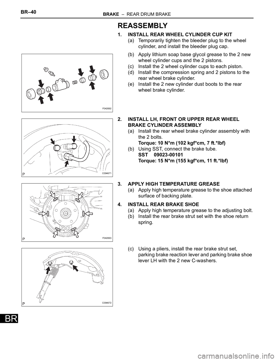
1. INSTALL REAR WHEEL CYLINDER CUP KIT
(a) Temporarily tighten the bleeder plug to the wheel
cylinder, and install the bleeder plug cap.
(b) Apply lithium soap base glycol grease to the 2 new
wheel cylinder cups and the 2 pistons.
(c) Install the 2 wheel cylinder cups to each piston.
(d) Install the compression spring and 2 pistons to the
rear wheel brake cylinder.
(e) Install the 2 new cylinder dust boots to the rear
wheel brake cylinder.
2. INSTALL LH, FRONT OR UPPER REAR WHEEL
BRAKE CYLINDER ASSEMBLY
(a) Install the rear wheel brake cylinder assembly with
the 2 bolts.
Torque: 10 N*m (102 kgf*cm, 7 ft.*lbf)
(b) Using SST, connect the brake tube.
SST 09023-00101
Torque: 15 N*m (155 kgf*cm, 11 ft.*lbf)
3. APPLY HIGH TEMPERATURE GREASE
(a) Apply high temperature grease to the shoe attached
surface of backing plate.
4. INSTALL REAR BRAKE SHOE
(a) Apply high temperature grease to the adjusting bolt.
(b) Install the rear brake strut set with the shoe return
spring.
(c) Using a pliers, install the rear brake strut set,
parking brake reaction lever and parking brake shoe
lever LH with the 2 new C-washers.
F042692
C094671
F042693
C094672
Page 2648 of 3000
BRAKE – REAR DRUM BRAKEBR–43
BR
(c) Using a screwdriver, back off the adjuster 15
notches.
(d) Install the hole plug.
9. FILL RESERVOIR WITH BRAKE FLUID (See page BR-
3)
10. BLEED BRAKE MASTER CYLINDER (See page BR-3)
11. BLEED BRAKE LINE (See page BR-4)
12. BLEED BRAKE ACTUATOR (w/ VSC) (See page BR-
4)
13. CHECK FLUID LEVEL IN RESERVOIR (See page BR-
7)
14. CHECK BRAKE FLUID LEAKAGE
15. INSTALL REAR WHEEL
Torque: 103 N*m (,050 kgf*cm, 76 ft.*lbf)
16. INSPECT PARKING BRAKE PEDAL TRAVEL
17. ADJUST PARKING BRAKE PEDAL TRAVEL
F040023E05
Page 2652 of 3000
PARKING BRAKE – PARKING BRAKE CABLEPB–13
PB
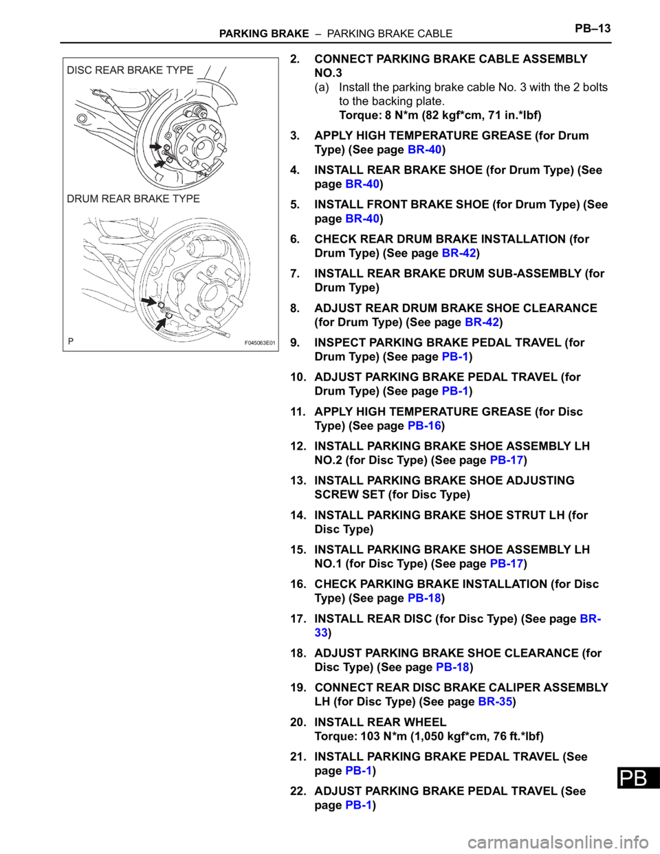
2. CONNECT PARKING BRAKE CABLE ASSEMBLY
NO.3
(a) Install the parking brake cable No. 3 with the 2 bolts
to the backing plate.
Torque: 8 N*m (82 kgf*cm, 71 in.*lbf)
3. APPLY HIGH TEMPERATURE GREASE (for Drum
Type) (See page BR-40)
4. INSTALL REAR BRAKE SHOE (for Drum Type) (See
page BR-40)
5. INSTALL FRONT BRAKE SHOE (for Drum Type) (See
page BR-40)
6. CHECK REAR DRUM BRAKE INSTALLATION (for
Drum Type) (See page BR-42)
7. INSTALL REAR BRAKE DRUM SUB-ASSEMBLY (for
Drum Type)
8. ADJUST REAR DRUM BRAKE SHOE CLEARANCE
(for Drum Type) (See page BR-42)
9. INSPECT PARKING BRAKE PEDAL TRAVEL (for
Drum Type) (See page PB-1)
10. ADJUST PARKING BRAKE PEDAL TRAVEL (for
Drum Type) (See page PB-1)
11. APPLY HIGH TEMPERATURE GREASE (for Disc
Type) (See page PB-16)
12. INSTALL PARKING BRAKE SHOE ASSEMBLY LH
NO.2 (for Disc Type) (See page PB-17)
13. INSTALL PARKING BRAKE SHOE ADJUSTING
SCREW SET (for Disc Type)
14. INSTALL PARKING BRAKE SHOE STRUT LH (for
Disc Type)
15. INSTALL PARKING BRAKE SHOE ASSEMBLY LH
NO.1 (for Disc Type) (See page PB-17)
16. CHECK PARKING BRAKE INSTALLATION (for Disc
Type) (See page PB-18)
17. INSTALL REAR DISC (for Disc Type) (See page BR-
33)
18. ADJUST PARKING BRAKE SHOE CLEARANCE (for
Disc Type) (See page PB-18)
19. CONNECT REAR DISC BRAKE CALIPER ASSEMBLY
LH (for Disc Type) (See page BR-35)
20. INSTALL REAR WHEEL
Torque: 103 N*m (1,050 kgf*cm, 76 ft.*lbf)
21. INSTALL PARKING BRAKE PEDAL TRAVEL (See
page PB-1)
22. ADJUST PARKING BRAKE PEDAL TRAVEL (See
page PB-1)
F045063E01
Page 2654 of 3000
PB–2PARKING BRAKE – PARKING BRAKE SYSTEM
PB
ADJUSTMENT
1. REMOVE REAR WHEEL
2. ADJUST PARKING BRAKE SHOE CLEARANCE (See
page PB-18)
3. INSTALL REAR WHEEL
Torque: 103 N*m (1,050 kgf*cm, 76 ft.*lbf)
4. INSPECT PARKING BRAKE PEDAL TRAVEL
(a) Slowly depress the parking brake pedal all the way,
and count the number of clicks.
Parking brake pedal travel:
3 to 5 clicks at 294 N (30 kgf, 66.0 lbf)
5. DISCONNECT BATTERY NEGATIVE TERMINAL
6. REMOVE FRONT DOOR SCUFF PLATE LH
7. REMOVE COWL SIDE TRIM BOARD LH (See page IP-
6)
8. REMOVE INSTRUMENT PANEL FINISH PANEL SUB-
ASSEMBLY LOWER LH
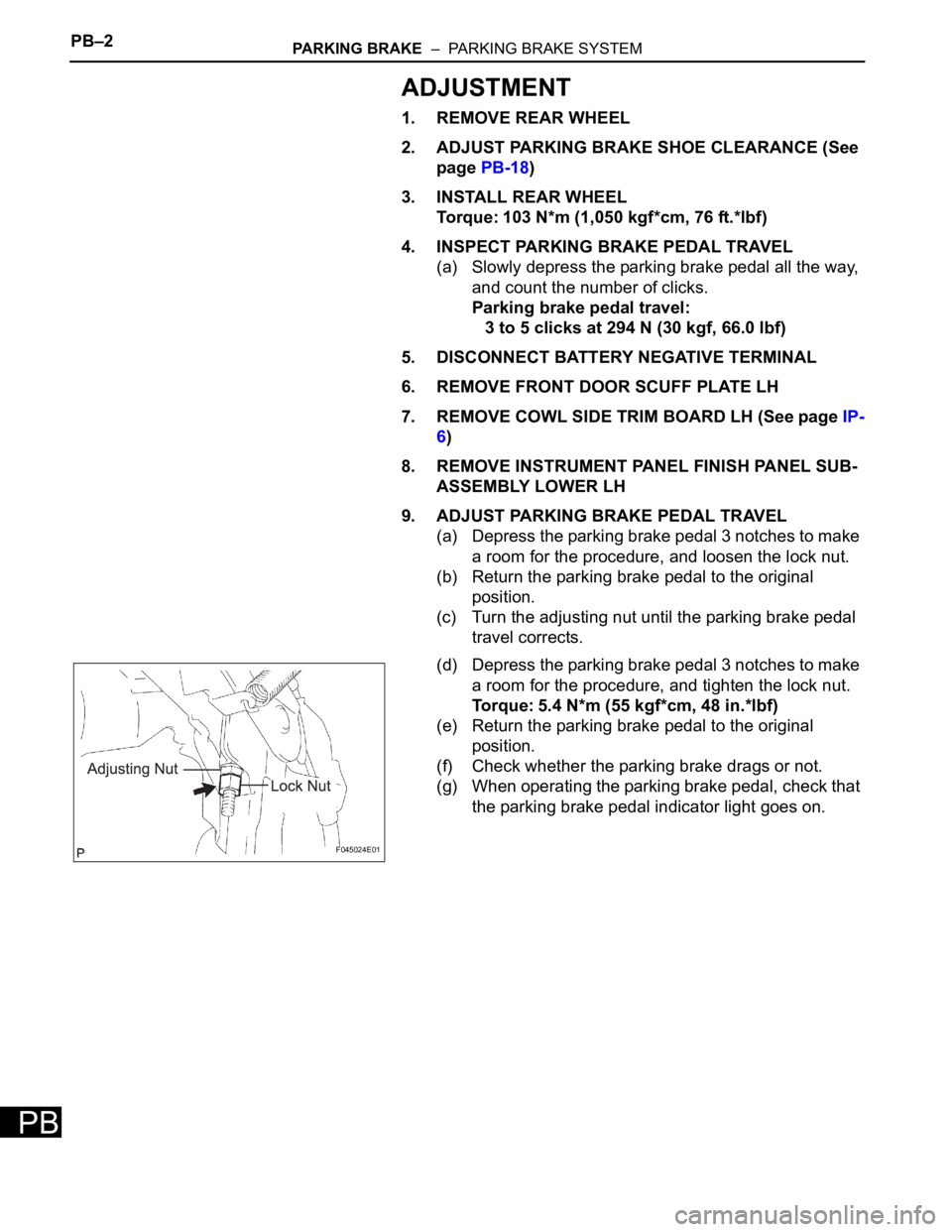
9. ADJUST PARKING BRAKE PEDAL TRAVEL
(a) Depress the parking brake pedal 3 notches to make
a room for the procedure, and loosen the lock nut.
(b) Return the parking brake pedal to the original
position.
(c) Turn the adjusting nut until the parking brake pedal
travel corrects.
(d) Depress the parking brake pedal 3 notches to make
a room for the procedure, and tighten the lock nut.
Torque: 5.4 N*m (55 kgf*cm, 48 in.*lbf)
(e) Return the parking brake pedal to the original
position.
(f) Check whether the parking brake drags or not.
(g) When operating the parking brake pedal, check that
the parking brake pedal indicator light goes on.
F045024E01