Page 21 of 3000
2GR-FE ENGINE CONTROL SYSTEM – KNOCK SENSORES–521
ES
REMOVAL
1. DISCHARGE FUEL SYSTEM PRESSURE
(See page FU-13)
2. REMOVE V-BANK COVER SUB-ASSEMBLY (See
page EM-28)
3. DRAIN ENGINE COOLANT (See page CO-6)
4. REMOVE WINDSHIELD WIPER MOTOR ASSEMBLY
HINT:
(See page WW-4)
5. REMOVE FRONT OUTER COWL TOP PANEL SUB-
ASSEMBLY (See page EM-27)
6. REMOVE AIR CLEANER CAP SUB-ASSEMBLY (See
page ES-493)
7. REMOVE AIR CLEANER CASE SUB-ASSEMBLY (See
page EM-28)
8. REMOVE INTAKE AIR SURGE TANK ASSEMBLY
(a) Disconnect the 2 water by-pass hoses from the
throttle body [A].
(b) Disconnect the vapor feed hose [B].
(c) Disconnect the throttle body connector and clamp
[C].
(d) Disconnect the ventilation hose [D].
(e) Disconnect the union to check valve hose [E].
(f) Disconnect the connector [F].
A129464E07
A138457E04
A129467
Page 22 of 3000
![TOYOTA SIENNA 2007 Service Repair Manual ES–5222GR-FE ENGINE CONTROL SYSTEM – KNOCK SENSOR
ES
(g) Using a 5 mm socket hexagon wrench, remove the
4 bolts [G].
(h) Remove the 2 nuts, 2 bolts and intake air surge tank
[H].
(i) Remove th TOYOTA SIENNA 2007 Service Repair Manual ES–5222GR-FE ENGINE CONTROL SYSTEM – KNOCK SENSOR
ES
(g) Using a 5 mm socket hexagon wrench, remove the
4 bolts [G].
(h) Remove the 2 nuts, 2 bolts and intake air surge tank
[H].
(i) Remove th](/manual-img/14/57466/w960_57466-21.png)
ES–5222GR-FE ENGINE CONTROL SYSTEM – KNOCK SENSOR
ES
(g) Using a 5 mm socket hexagon wrench, remove the
4 bolts [G].
(h) Remove the 2 nuts, 2 bolts and intake air surge tank
[H].
(i) Remove the gasket from the intake air surge tank [I].
9. REMOVE FUEL MAIN TUBE SUB-ASSEMBLY (See
page EM-30)
10. REMOVE INTAKE MANIFOLD (See page EM-39)
11. REMOVE KNOCK CONTROL SENSOR
(a) Disconnect the 2 knock sensor connectors.
(b) Remove the 2 bolts and then remove the 2 knock
control sensors.
INSPECTION
1. KNOCK CONTROL SENSOR
(a) Using an ohmmeter, measure the resistance
between the terminals.
Resistance:
120 to 280 k
at 20C (68F)
If the resistance is not specified, replace the knock
control sensor.
INSTALLATION
1. INSTALL KNOCK CONTROL SENSOR
(a) Install the 2 knock control sensors with the 2 bolts
as shown in the illustration.
Torque: 20 N*m (204 kgf*cm, 15 ft.*lbf)
(b) Connect the 2 knock control sensor connectors.
2. INSTALL INTAKE MANIFOLD (See page EM-49)
3. INSTALL FUEL MAIN TUBE SUB-ASSEMBLY (See
page EM-56)
4. INSTALL INTAKE AIR SURGE TANK
NOTICE:
DO NOT apply oil to the bolts listed below.
A129468E08
A129615
A065174
A132951E01
Tightening PartsTo r q u e
N*m (kgf*cm, ft.*lbf)QTY
Surge Tank and Intake Manifold 18 (184, 13) 4
No. 1 Surge Tank Stay and Surge Tank 21 (214, 15) 1
Throttle Body Bracket and Surge Tank 21 (214, 15) 1
Page 23 of 3000
![TOYOTA SIENNA 2007 Service Repair Manual 2GR-FE ENGINE CONTROL SYSTEM – KNOCK SENSORES–523
ES
(a) Install a new gasket to the intake air surge tank [A].
(b) Using a 5 mm hexagon socket wrench, install the 4
bolts [B].
Torque: 18 N*m ( TOYOTA SIENNA 2007 Service Repair Manual 2GR-FE ENGINE CONTROL SYSTEM – KNOCK SENSORES–523
ES
(a) Install a new gasket to the intake air surge tank [A].
(b) Using a 5 mm hexagon socket wrench, install the 4
bolts [B].
Torque: 18 N*m (](/manual-img/14/57466/w960_57466-22.png)
2GR-FE ENGINE CONTROL SYSTEM – KNOCK SENSORES–523
ES
(a) Install a new gasket to the intake air surge tank [A].
(b) Using a 5 mm hexagon socket wrench, install the 4
bolts [B].
Torque: 18 N*m (184 kgf*cm, 13 ft.*lbf)
(c) Install the intake air surge tank with the 2 nuts and 2
bolts [C].
Torque: Nut
16 N*m (163 kgf*cm, 12 ft.*lbf)
Bolt
21 N*m (214 kgf*cm, 15 ft.*lbf)
(d) Connect the connector [D].
(e) Connect the union to check valve hose [E].
(f) Connect the ventilation hose No. 2 [F].
(g) Install the clamp and connect the throttle with motor
body assembly connector [G].
(h) Connect the vapor feed hose [H].
(i) Connect the 2 water by-pass hoses to the throttle
with motor body assembly [I].
5. INSTALL AIR CLEANER CASE SUB-ASSEMBLY (See
page EM-59)
6. INSTALL AIR CLEANER CAP SUB-ASSEMBLY (See
page ES-496)
7. ADD ENGINE COOLANT (See page CO-7)
8. INSPECT FOR ENGINE COOLANT LEAK (See page
CO-1)
9. INSPECT FOR FUEL LEAK (See page FU-7)
10. INSTALL FRONT OUTER COWL TOP PANEL SUB-
ASSEMBLY (See page EM-61)
11. INSTALL WINDSHIELD WIPER MOTOR ASSEMBLY
HINT:
(See page WW-5)
A129468E09
A129467
A138457E05
A129464E08
Page 25 of 3000

EM–262GR-FE ENGINE MECHANICAL – ENGINE ASSEMBLY
EM
REMOVAL
1. DISCHARGE FUEL SYSTEM PRESSURE (See page
FU-13)
2. DISCHARGE REFRIGERANT FROM
REFRIGERATION SYSTEM (See page AC-172)
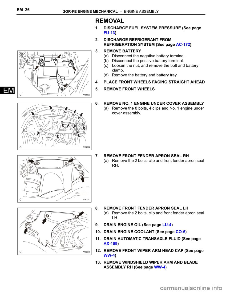
3. REMOVE BATTERY
(a) Disconnect the negative battery terminal.
(b) Disconnect the positive battery terminal.
(c) Loosen the nut, and remove the bolt and battery
clamp.
(d) Remove the battery and battery tray.
4. PLACE FRONT WHEELS FACING STRAIGHT AHEAD
5. REMOVE FRONT WHEELS
6. REMOVE NO. 1 ENGINE UNDER COVER ASSEMBLY
(a) Remove the 8 bolts, 4 clips and No. 1 engine under
cover assembly.
7. REMOVE FRONT FENDER APRON SEAL RH
(a) Remove the 2 bolts, clip and front fender apron seal
RH.
8. REMOVE FRONT FENDER APRON SEAL LH
(a) Remove the 2 bolts, clip and front fender apron seal
LH.
9. DRAIN ENGINE OIL (See page LU-4)
10. DRAIN ENGINE COOLANT (See page CO-6)
11. DRAIN AUTOMATIC TRANSAXLE FLUID (See page
AX-159)
12. REMOVE FRONT WIPER ARM HEAD CAP (See page
WW-4)
13. REMOVE WINDSHIELD WIPER ARM AND BLADE
ASSEMBLY RH (See page WW-4)
A155033
A162362
A162371
A162370
Page 42 of 3000
2GR-FE FUEL – FUEL SYSTEMFU–5
FU
PARTS LOCATION
A162578E01
Page 43 of 3000
FU–62GR-FE FUEL – FUEL SYSTEM
FU
SYSTEM DIAGRAM
A163147E01
Page 44 of 3000

2GR-FE EMISSION CONTROL – EMISSION CONTROL SYSTEMEC–5
EC
ON-VEHICLE INSPECTION
1. INSPECT FUEL CUT RPM
(a) Increase the engine speed to at least 3500 rpm.
(b) Use a sound scope to check for injector operating
sounds.
(c) Check that when the throttle lever is released,
injector operating sounds stop momentarily (at 2500
rpm) and then resume (at 1400 rpm).
Standard
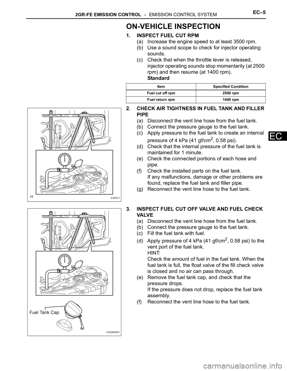
2. CHECK AIR TIGHTNESS IN FUEL TANK AND FILLER
PIPE
(a) Disconnect the vent line hose from the fuel tank.
(b) Connect the pressure gauge to the fuel tank.
(c) Apply pressure to the fuel tank to create an internal
pressure of 4 kPa (41 gf/cm
2, 0.58 psi).
(d) Check that the internal pressure of the fuel tank is
maintained for 1 minute.
(e) Check the connected portions of each hose and
pipe.
(f) Check the installed parts on the fuel tank.
If any malfunctions, damage or other problems are
found, replace the fuel tank and filler pipe.
(g) Reconnect the vent line hose to the fuel tank.
3. INSPECT FUEL CUT OFF VALVE AND FUEL CHECK
VA LV E
(a) Disconnect the vent line hose from the fuel tank.
(b) Connect the pressure gauge to the fuel tank.
(c) Fill the fuel tank with fuel.
(d) Apply pressure of 4 kPa (41 gf/cm
2, 0.58 psi) to the
vent port of the fuel tank.
HINT:
Check the amount of fuel in the fuel tank. When the
fuel tank is full, the float valve of the fill check valve
is closed and no air can pass through.
(e) Remove the fuel tank cap, and check that the
pressure drops.
If the pressure does not drop, replace the fuel tank
assembly.
(f) Reconnect the vent line hose to the fuel tank.
Item Specified Condition
Fuel cut off rpm 2500 rpm
Fuel return rpm 1400 rpm
A163311
A163504E01
Page 58 of 3000

INTRODUCTION – TERMSIN–51
IN
IFI Indirect Fuel Injection Indirect Injection (IDL)
IFS Inertia Fuel-Shutoff -
ISC Idle Speed Control -
KS Knock Sensor Knock Sensor
MAF Mass Airflow Air Flow Meter
MAP Manifold Absolute Pressure Manifold Pressure Intake Vacuum
MC Mixture ControlElectric Bleed Air Control Valve (EBCV)
Mixture Control Valve (MCV)
Electric Air Control Valve (EACV)
MDP Manifold Differential Pressure -
MFI Multiport Fuel Injection Electronic Fuel Injection (EFI)
MIL Malfunction Indicator Light Check Engine Light
MST Manifold Surface Temperature -
MVZ Manifold Vacuum Zone -
NVRAM Non-Volatile Random Access Memory -
O2S Oxygen SensorOxygen Sensor, O
2 Sensor (O2S)
OBD On-Board Diagnostic On-Board Diagnostic System (OBD)
OC Oxidation Catalytic Converter Oxidation Catalytic Convert (OC), CCo
OL Open Loop Open Loop
PAIR Pulsed Secondary Air Injection Air Suction (AS)
PCM Powertrain Control Module -
PNP Park/Neutral Position -
PROM Programmable Read Only Memory -
PSP Power Steering Pressure -
PTOX Periodic Trap OxidizerDiesel Particulate Filter (DPF)
Diesel Particulate Trap (DPT)
RAM Random Access Memory Random Access Memory (RAM)
RM Relay Module -
ROM Read Only Memory Read Only Memory (ROM)
RPM Engine Speed Engine Speed
SC Supercharger Supercharger
SCB Supercharger Bypass E-ABV
SFI Sequential Multiport Fuel Injection Electronic Fuel Injection (EFI), Sequential Injection
SPL Smoke Puff Limiter -
SRI Service Reminder Indicator -
SRT System Readiness Test -
ST Scan Tool -
TB Throttle Body Throttle Body
TBI Throttle Body Fuel InjectionSingle Point Injection
Central Fuel Injection (Ci)
TC Turbocharger Turbocharger
TCC Torque Converter Clutch Torque Converter
TCM Transmission Control Module Transmission ECU, ECT ECU
TP Throttle Position Throttle Position
TR Transmission Range -
TVV Thermal Vacuum ValveBimetallic Vacuum Switching Valve (BVSV)
Thermostatic Vacuum Switching Valve (TVSV)
TWC Three-Way Catalytic ConverterThree-Way Catalytic (TWC)
Manifold Converter
CC
RO
SAE
ABBREVIATIONSSAE TERMSTOYOTA TERMS
( )-ABBREVIATIONS