2007 TOYOTA SIENNA Fuel System
[x] Cancel search: Fuel SystemPage 365 of 3000

2GR-FE ENGINE CONTROL SYSTEM – SFI SYSTEMES–47
ES
KNOCK FB VAL Feedback value of knocking -
ACCEL POS #1Absolute Accelerator Pedal Position (APP)
No. 1-
ACCEL POS #2 Absolute APP No. 2 -
THROTTLE POS Throttle positionRead value with ignition switch on (Do not
start engine)
THROTTLE POS Throttle sensor positioningRead value with ignition switch on (Do not
start engine)
THROTTLE POS#2 Throttle sensor positioning #2Read value with ignition switch on (Do not
start engine)
THROTTLE MOT Throttle motor -
O2S B1 S2 Heated oxygen sensor outputPerforming INJ VOL or A/F CONTROL
function of ACTIVE TEST enables technician
to check voltage output of sensor
O2S B2 S2 Heated oxygen sensor outputPerforming INJ VOL or A/F CONTROL
function of ACTIVE TEST enables technician
to check voltage output of sensor
AFS B1 S1 A/F sensor outputPerforming INJ VOL or A/F CONTROL
function of ACTIVE TEST enables technician
to check voltage output of sensor
AFS B2 S1 A/F sensor outputPerforming INJ VOL or A/F CONTROL
function of ACTIVE TEST enables technician
to check voltage output of sensor
TOTAL FT #1 Total fuel trim of bank 1 -
TOTAL FT #2 Total fuel trim of bank 2 -
SHORT FT #1 Short-term fuel trim of bank 1Short-term fuel compensation used to
maintain air-fuel ratio at stoichiometric air-fuel
ratio
LONG FT #1 Long-term fuel trim of bank 1Overall fuel compensation carried out in long-
term to compensate for a continual deviation
of short-term fuel trim from central valve
SHORT FT #2 Short-term fuel trim of bank 2Short-term fuel compensation used to
maintain air-fuel ratio at stoichiometric air-fuel
ratio
LONG FT #2 Long-term fuel trim of bank 2Overall fuel compensation carried out in long-
term to compensate for a continual deviation
of short-term fuel trim from central valve
FUEL SYS #1 Fuel system status (bank 1)• OL (Open Loop): Has not yet satisfied
conditions to go closed loop
• CL (Closed Loop): Using heated oxygen
sensor as feedback for fuel control
• OL DRIVE: Open loop due to driving
conditions (fuel enrichment)
• OL FAULT: Open loop due to detected
system fault
• CL FAULT: Closed loop but heated
oxygen sensor, which used for fuel control
malfunctioning
FUEL SYS #2 Fuel system status (bank 2)• OL (Open Loop): Has not yet satisfied
conditions to go closed loop
• CL (Closed Loop): Using heated oxygen
sensor as feedback for fuel control
• OL DRIVE: Open loop due to driving
conditions (fuel enrichment)
• OL FAULT: Open loop due to detected
system fault
• CL FAULT: Closed loop but heated
oxygen sensor, which used for fuel control
malfunctioning
O2FT B1 S2 Fuel trim at heated oxygen sensor Same as SHORT FT #1LABEL
(Intelligent Tester Display)Measurement Item Diagnostic Note
Page 366 of 3000

ES–482GR-FE ENGINE CONTROL SYSTEM – SFI SYSTEM
ES
O2FT B2 S2 Fuel trim at heated oxygen sensor Same as SHORT FT #2
AF FT B1 S1 Fuel trim at A/F sensor -
AF FT B2 S1 Fuel trim at A/F sensor -
CAT TEMP B1 S1 Catalyst temperature -
CAT TEMP B2 S1 Catalyst temperature -
CAT TEMP B1 S2 Catalyst temperature -
CAT TEMP B2 S2 Catalyst temperature -
S O2S B1 S2 Heated oxygen sensor impedance (Sensor 2) -
S O2S B2 S2 Heated oxygen sensor impedance (Sensor 2) -
INI COOL TEMP Initial engine coolant temperature -
INI INTAKE TEMP Initial intake air temperature -
INJ VOL Injection volume -
STARTER SIG Starter signal -
PS SW Power steering signal -
PS SIGNAL Power steering signal (history)This signal status usually ON until ignition
switch turned off
CTP SW Closed throttle position switch -
A/C SIGNAL A/C signal -
ELECT LOAD SIG Electrical load signal -
STOP LIGHT SW Stop light switch -
BATTERY VOLTAGE Battery voltage -
ATM PRESSURE Atmospheric pressure -
FUEL PMP SP CTL Fuel pump speed control status -
ACIS VSVVSV for Air Intake Control Induction System
(AICS)-
VVT CTRL B2 VVT control (bank 2 Intake side) status -
EVAP (Purge) VSV EVAP purge VSV -
FUEL PUMP/SPD Fuel pump speed statusVSV for EVAP controlled by ECM (ground
side duty control)
VACUUM PUMP Key-off EVAP system pump status -
EVAP VENT VAL Key-off EVAP system vent valve status -
FAN MOTOR Electric fan motor -
TC/TE1 TC and TE1 terminals of DLC3 -
ACM ACM control status -
VVTL AIM ANGL #1 VVT aim angle -
VVT CHNG ANGL #1 VVT change angle -
VVT OCV DUTY B1 VVT OCV operation duty -
VVT EX HOLD B1VVT exhaust hold duty ratio learning value
(bank 1 Exhaust side)-
VVT EX CHG ANG1 VVT change angle (bank 1 Exhaust side) -
VVT EX OCV D B1VVT OCV (bank 1 Exhaust side) operation
duty-
VVTL AIM ANGL#2 VVT aim angle (bank 2 Intake side) -
VVT CHNG ANGL#2 VVT change angle (bank 2 Intake side) -
VVT OCV DUTY B2 VVT OCV (bank 2 Intake side) operation duty -
VVT EX HOLD B2VVT exhaust hold duty ratio learning value
(bank 2 Exhaust side)-
VVT EX CHG ANG2 VVT change angle (bank 2 Exhaust side) -
VVT EX OCV D B2VVT OCV (bank 2 Exhaust side) operation
duty- LABEL
(Intelligent Tester Display)Measurement Item Diagnostic Note
Page 367 of 3000

2GR-FE ENGINE CONTROL SYSTEM – SFI SYSTEMES–49
ES
FC IDL Idle fuel cutON: when throttle valve fully closed and
engine speed over 1500 rpm
FC TAU FC TAUFuel cut initiated under light load to prevent
incomplete combustion
IGNITION Ignition -
CYL #1 Cylinder #1 misfire rate Displayed only during idling
CYL #2 Cylinder #2 misfire rate Displayed only during idling
CYL #3 Cylinder #3 misfire rate Displayed only during idling
CYL #4 Cylinder #4 misfire rate Displayed only during idling
CYL #5 Cylinder #5 misfire rate Displayed only during idling
CYL #6 Cylinder #6 misfire rate Displayed only during idling
CYL ALL All cylinder misfire rate Displayed only during idling
MISFIRE RPM Misfire RPM -
MISFIRE LOAD Misfire load -
MISFIRE MARGIN Misfire monitoring -
ENG RUN TIME Accumulated engine running time -
TIME DTC CLEAR Cumulative time after DTC cleared -
DIST DTC CLEAR Accumulated distance after DTC cleared -
WU CYC DTC CLEAR Warm-up cycle after DTC cleared -LABEL
(Intelligent Tester Display)Measurement Item Diagnostic Note
Page 369 of 3000

2GR-FE ENGINE CONTROL SYSTEM – SFI SYSTEMES–51
ES
FAIL-SAFE CHART
If any of the following DTCs are set, the ECM enters fail-safe
mode to allow the vehicle to be driven temporarily.
HINT:
• *1: The vehicle can be driven slowly when the accelerator
pedal is depressed firmly and slowly. If the accelerator
pedal is depressed quickly, the vehicle may speed up and
slow down erratically.
• *2: Misfire related fail-safe operations occur when catalyst
overheat malfunctions occur.
DTCs Components Fail-Safe OperationsFail-Safe Deactivation
Conditions
P0031, P0032, P0051 and P0052Air-Fuel Ratio (A/F) Sensor
HeaterECM turns off A/F sensor heater Ignition switch off
P0037, P0038, P0057 and P0058Heated Oxygen (HO2) Sensor
HeaterECM turns off HO2 sensor heater Ignition switch off
P0100, P0102 and P0103 Mass Air Flow (MAF) MeterECM calculates ignition timing
according to engine speed and
throttle valve positionPass condition detected
P0110, P0112 and P0113Intake Air Temperature (IAT)
SensorECM estimates IAT to be 20
C
(68
F)Pass condition detected
P0115, P0117 and P0118Engine Coolant Temperature
(ECT) SensorECM estimates ECT to be 80
C
(176
F)Pass condition detected
P0120, P0121, P0122, P0123,
P0220, P0222, P0223, P0604,
P0606, P0607, P0657, P2102,
P2103, P2111, P2112, P2118,
P2119 and P2135Electronic Throttle Control
System (ETCS)ECM cuts off throttle actuator
current and throttle valve returned
to 6.5
throttle position by return
spring
ECM then adjusts engine output
by controlling fuel injection
(intermittent fuel-cut) and ignition
timing in accordance with
accelerator pedal opening angle,
to allow vehicle to continue at
minimal speed*1Pass condition detected and then
ignition switch turned off
P0300, P0301, P0302, P0303,
P0304, P0305 and P0306*2• Fuel injector
• Electronic Throttle Control
System (ETCS)When misfire occurs, fuel cut is
performed for catalyst overheat
malfunction prevention
• During normal load and
normal engine speed (MIL is
blinking)
- Fuel cut is performed on
malfunctioning cylinder
• During high load and high
engine speed (MIL is
blinking)
- Throttle valve opening angle
control is performed
- All cylinder fuel cut or
malfunction cylinder fuel cutPass condition detected and then
ignition switch turned OFF
P0327, P0328, P0332 and P0333 Knock SensorECM sets ignition timing to
maximum retardIgnition switch off
P0351 to P0356 Igniter ECM cuts fuel Pass condition detected
P2120, P2121, P2122, P2123,
P2125, P2127, P2128 and P2138Accelerator Pedal Position (APP)
SensorAPP sensor has 2 sensor circuits:
Main and Sub
If either of circuits malfunctions,
ECM controls engine using the
other circuit
If both of circuits malfunction,
ECM regards accelerator pedal
as being released. As a result,
throttle valve is closed and engine
idlesPass condition detected and then
ignition switch turned off
Page 374 of 3000

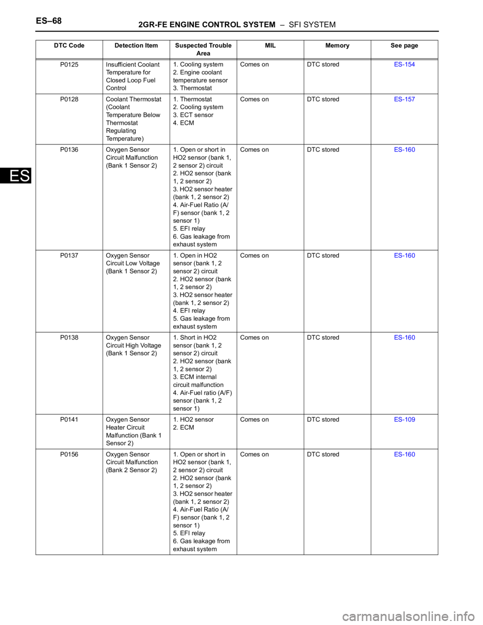
ES–682GR-FE ENGINE CONTROL SYSTEM – SFI SYSTEM
ES
P0125 Insufficient Coolant
Temperature for
Closed Loop Fuel
Control1. Cooling system
2. Engine coolant
temperature sensor
3. ThermostatComes on DTC storedES-154
P0128 Coolant Thermostat
(Coolant
Temperature Below
Thermostat
Regulating
Temperature)1. Thermostat
2. Cooling system
3. ECT sensor
4. ECMComes on DTC storedES-157
P0136 Oxygen Sensor
Circuit Malfunction
(Bank 1 Sensor 2)1. Open or short in
HO2 sensor (bank 1,
2 sensor 2) circuit
2. HO2 sensor (bank
1, 2 sensor 2)
3. HO2 sensor heater
(bank 1, 2 sensor 2)
4. Air-Fuel Ratio (A/
F) sensor (bank 1, 2
sensor 1)
5. EFI relay
6. Gas leakage from
exhaust systemComes on DTC storedES-160
P0137 Oxygen Sensor
Circuit Low Voltage
(Bank 1 Sensor 2)1. Open in HO2
sensor (bank 1, 2
sensor 2) circuit
2. HO2 sensor (bank
1, 2 sensor 2)
3. HO2 sensor heater
(bank 1, 2 sensor 2)
4. EFI relay
5. Gas leakage from
exhaust systemComes on DTC storedES-160
P0138 Oxygen Sensor
Circuit High Voltage
(Bank 1 Sensor 2)1. Short in HO2
sensor (bank 1, 2
sensor 2) circuit
2. HO2 sensor (bank
1, 2 sensor 2)
3. ECM internal
circuit malfunction
4. Air-Fuel ratio (A/F)
sensor (bank 1, 2
sensor 1)Comes on DTC storedES-160
P0141 Oxygen Sensor
Heater Circuit
Malfunction (Bank 1
Sensor 2)1. HO2 sensor
2. ECMComes on DTC storedES-109
P0156 Oxygen Sensor
Circuit Malfunction
(Bank 2 Sensor 2)1. Open or short in
HO2 sensor (bank 1,
2 sensor 2) circuit
2. HO2 sensor (bank
1, 2 sensor 2)
3. HO2 sensor heater
(bank 1, 2 sensor 2)
4. Air-Fuel Ratio (A/
F) sensor (bank 1, 2
sensor 1)
5. EFI relay
6. Gas leakage from
exhaust systemComes on DTC storedES-160 DTC Code Detection Item Suspected Trouble
AreaMIL Memory See page
Page 375 of 3000

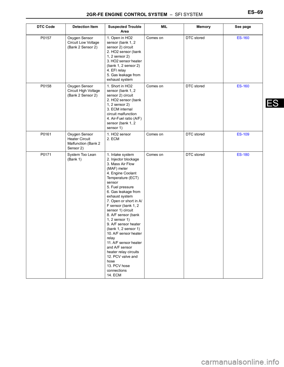
2GR-FE ENGINE CONTROL SYSTEM – SFI SYSTEMES–69
ES
P0157 Oxygen Sensor
Circuit Low Voltage
(Bank 2 Sensor 2)1. Open in HO2
sensor (bank 1, 2
sensor 2) circuit
2. HO2 sensor (bank
1, 2 sensor 2)
3. HO2 sensor heater
(bank 1, 2 sensor 2)
4. EFI relay
5. Gas leakage from
exhaust systemComes on DTC storedES-160
P0158 Oxygen Sensor
Circuit High Voltage
(Bank 2 Sensor 2)1. Short in HO2
sensor (bank 1, 2
sensor 2) circuit
2. HO2 sensor (bank
1, 2 sensor 2)
3. ECM internal
circuit malfunction
4. Air-Fuel ratio (A/F)
sensor (bank 1, 2
sensor 1)Comes on DTC storedES-160
P0161 Oxygen Sensor
Heater Circuit
Malfunction (Bank 2
Sensor 2)1. HO2 sensor
2. ECMComes on DTC storedES-109
P0171 System Too Lean
(Bank 1)1. Intake system
2. Injector blockage
3. Mass Air Flow
(MAF) meter
4. Engine Coolant
Temperature (ECT)
sensor
5. Fuel pressure
6. Gas leakage from
exhaust system
7. Open or short in A/
F sensor (bank 1, 2
sensor 1) circuit
8. A/F sensor (bank
1, 2 sensor 1)
9. A/F sensor heater
(bank 1, 2 sensor 1)
10. A/F sensor heater
relay
11. A/F sensor heater
and A/F sensor
heater relay circuits
12. PCV valve and
hose
13. PCV hose
connections
14. ECMComes on DTC storedES-180 DTC Code Detection Item Suspected Trouble
AreaMIL Memory See page
Page 376 of 3000

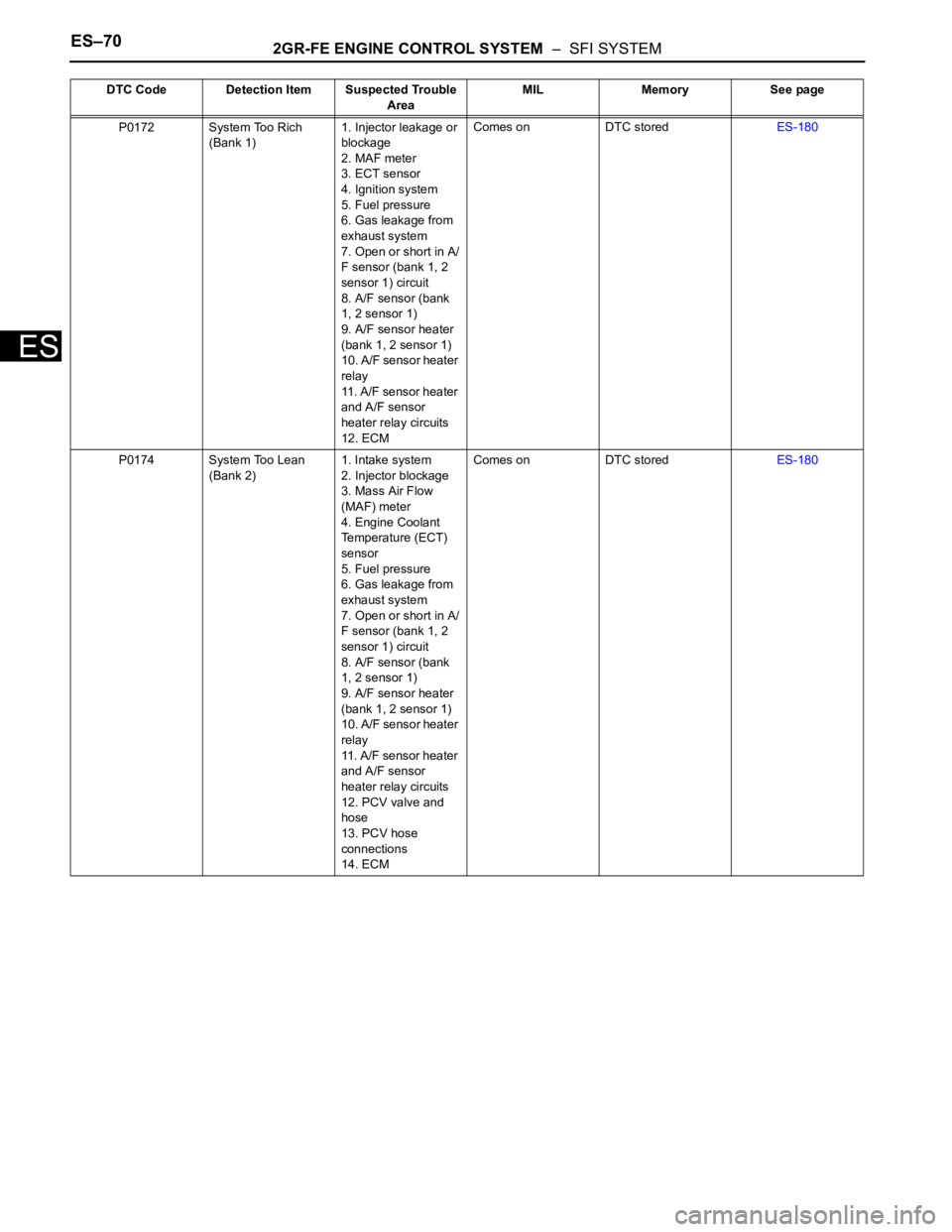
ES–702GR-FE ENGINE CONTROL SYSTEM – SFI SYSTEM
ES
P0172 System Too Rich
(Bank 1)1. Injector leakage or
blockage
2. MAF meter
3. ECT sensor
4. Ignition system
5. Fuel pressure
6. Gas leakage from
exhaust system
7. Open or short in A/
F sensor (bank 1, 2
sensor 1) circuit
8. A/F sensor (bank
1, 2 sensor 1)
9. A/F sensor heater
(bank 1, 2 sensor 1)
10. A/F sensor heater
relay
11. A/F sensor heater
and A/F sensor
heater relay circuits
12. ECMComes on DTC storedES-180
P0174 System Too Lean
(Bank 2)1. Intake system
2. Injector blockage
3. Mass Air Flow
(MAF) meter
4. Engine Coolant
Temperature (ECT)
sensor
5. Fuel pressure
6. Gas leakage from
exhaust system
7. Open or short in A/
F sensor (bank 1, 2
sensor 1) circuit
8. A/F sensor (bank
1, 2 sensor 1)
9. A/F sensor heater
(bank 1, 2 sensor 1)
10. A/F sensor heater
relay
11. A/F sensor heater
and A/F sensor
heater relay circuits
12. PCV valve and
hose
13. PCV hose
connections
14. ECMComes on DTC storedES-180 DTC Code Detection Item Suspected Trouble
AreaMIL Memory See page
Page 377 of 3000

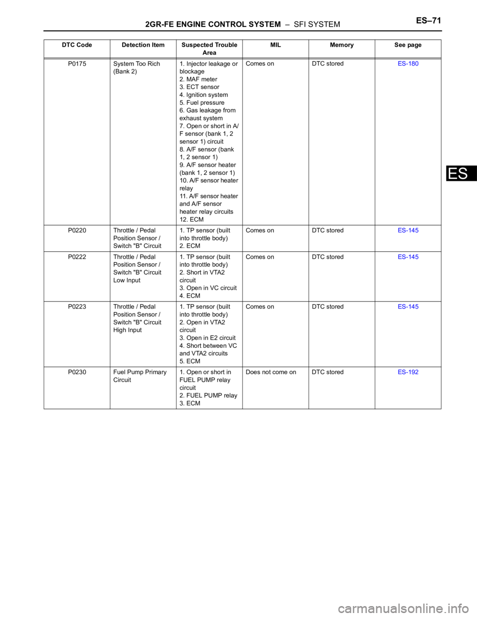
2GR-FE ENGINE CONTROL SYSTEM – SFI SYSTEMES–71
ES
P0175 System Too Rich
(Bank 2)1. Injector leakage or
blockage
2. MAF meter
3. ECT sensor
4. Ignition system
5. Fuel pressure
6. Gas leakage from
exhaust system
7. Open or short in A/
F sensor (bank 1, 2
sensor 1) circuit
8. A/F sensor (bank
1, 2 sensor 1)
9. A/F sensor heater
(bank 1, 2 sensor 1)
10. A/F sensor heater
relay
11. A/F sensor heater
and A/F sensor
heater relay circuits
12. ECMComes on DTC storedES-180
P0220 Throttle / Pedal
Position Sensor /
Switch "B" Circuit1. TP sensor (built
into throttle body)
2. ECMComes on DTC storedES-145
P0222 Throttle / Pedal
Position Sensor /
Switch "B" Circuit
Low Input1. TP sensor (built
into throttle body)
2. Short in VTA2
circuit
3. Open in VC circuit
4. ECMComes on DTC storedES-145
P0223 Throttle / Pedal
Position Sensor /
Switch "B" Circuit
High Input1. TP sensor (built
into throttle body)
2. Open in VTA2
circuit
3. Open in E2 circuit
4. Short between VC
and VTA2 circuits
5. ECMComes on DTC storedES-145
P0230 Fuel Pump Primary
Circuit1. Open or short in
FUEL PUMP relay
circuit
2. FUEL PUMP relay
3. ECMDoes not come on DTC storedES-192 DTC Code Detection Item Suspected Trouble
AreaMIL Memory See page