2007 TOYOTA SIENNA Fuel System
[x] Cancel search: Fuel SystemPage 378 of 3000
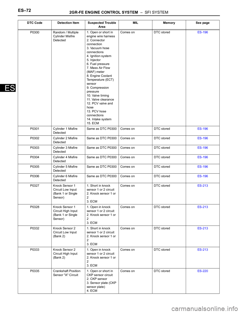
ES–722GR-FE ENGINE CONTROL SYSTEM – SFI SYSTEM
ES
P0300 Random / Multiple
Cylinder Misfire
Detected1. Open or short in
engine wire harness
2. Connector
connection
3. Vacuum hose
connections
4. Ignition system
5. Injector
6. Fuel pressure
7. Mass Air Flow
(MAF) meter
8. Engine Coolant
Temperature (ECT)
sensor
9. Compression
pressure
10. Valve timing
11. Valve clearance
12. PCV valve and
hose
13. PCV hose
connections
14. Intake system
15. ECMComes on DTC storedES-196
P0301 Cylinder 1 Misfire
DetectedSame as DTC P0300 Comes on DTC storedES-196
P0302 Cylinder 2 Misfire
DetectedSame as DTC P0300 Comes on DTC storedES-196
P0303 Cylinder 3 Misfire
DetectedSame as DTC P0300 Comes on DTC storedES-196
P0304 Cylinder 4 Misfire
DetectedSame as DTC P0300 Comes on DTC storedES-196
P0305 Cylinder 5 Misfire
DetectedSame as DTC P0300 Comes on DTC storedES-196
P0306 Cylinder 6 Misfire
DetectedSame as DTC P0300 Comes on DTC storedES-196
P0327 Knock Sensor 1
Circuit Low Input
(Bank 1 or Single
Sensor)1. Short in knock
sensor 1 or 2 circuit
2. Knock sensor 1 or
2
3. ECMComes on DTC storedES-213
P0328 Knock Sensor 1
Circuit High Input
(Bank 1 or Single
Sensor)1. Open in knock
sensor 1 or 2 circuit
2. Knock sensor 1 or
2
3. ECMComes on DTC storedES-213
P0332 Knock Sensor 2
Circuit Low Input
(Bank 2)1. Short in knock
sensor 1 or 2 circuit
2. Knock sensor 1 or
2
3. ECMComes on DTC storedES-213
P0333 Knock Sensor 2
Circuit High Input
(Bank 2)1. Open in knock
sensor 1 or 2 circuit
2. Knock sensor 1 or
2
3. ECMComes on DTC storedES-213
P0335 Crankshaft Position
Sensor "A" Circuit1. Open or short in
CKP sensor circuit
2. CKP sensor
3. Sensor plate (CKP
sensor plate)
4. ECMComes on DTC storedES-220 DTC Code Detection Item Suspected Trouble
AreaMIL Memory See page
Page 382 of 3000
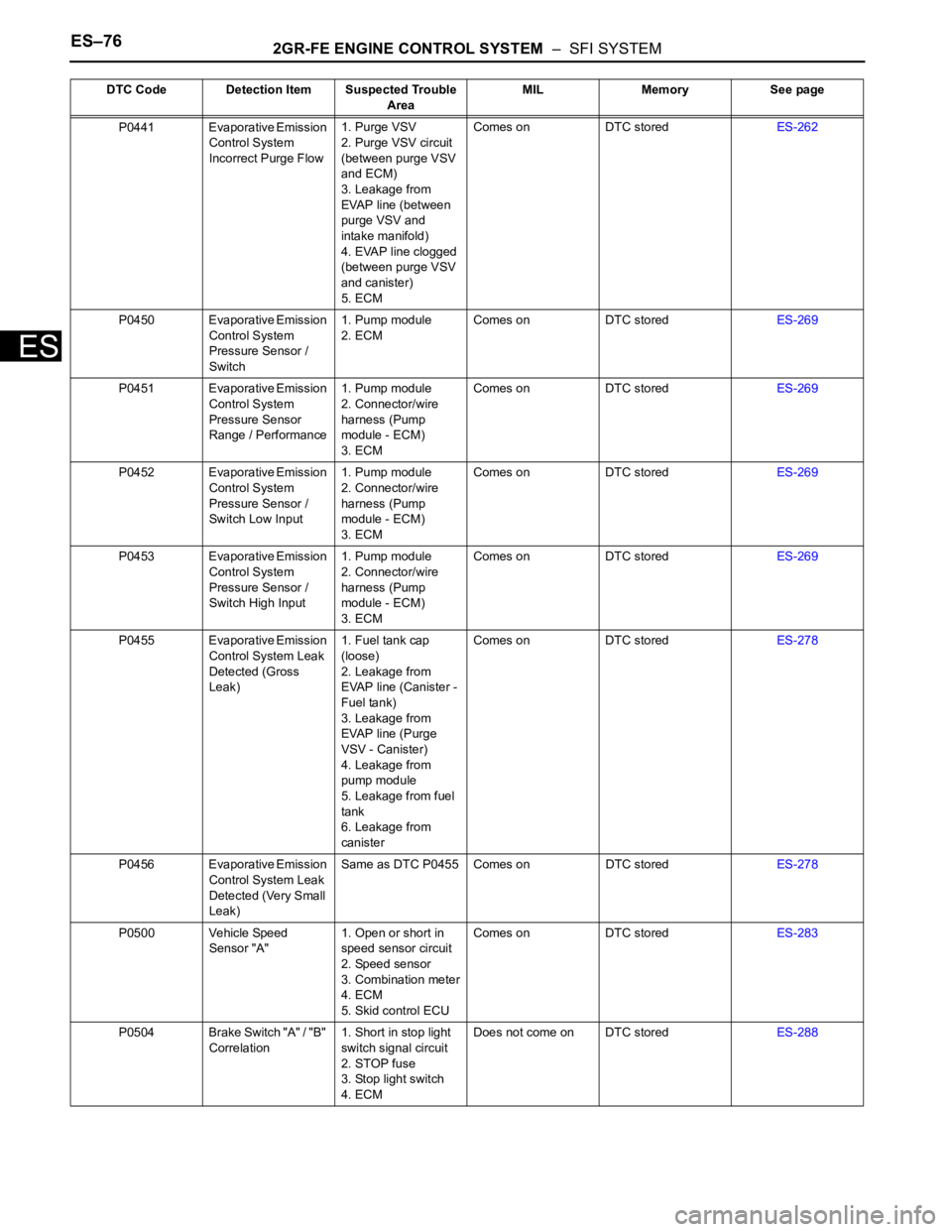
ES–762GR-FE ENGINE CONTROL SYSTEM – SFI SYSTEM
ES
P0441 Evaporative Emission
Control System
Incorrect Purge Flow1. Purge VSV
2. Purge VSV circuit
(between purge VSV
and ECM)
3. Leakage from
EVAP line (between
purge VSV and
intake manifold)
4. EVAP line clogged
(between purge VSV
and canister)
5. ECMComes on DTC storedES-262
P0450 Evaporative Emission
Control System
Pressure Sensor /
Switch1. Pump module
2. ECMComes on DTC storedES-269
P0451 Evaporative Emission
Control System
Pressure Sensor
Range / Performance1. Pump module
2. Connector/wire
harness (Pump
module - ECM)
3. ECMComes on DTC storedES-269
P0452 Evaporative Emission
Control System
Pressure Sensor /
Switch Low Input1. Pump module
2. Connector/wire
harness (Pump
module - ECM)
3. ECMComes on DTC storedES-269
P0453 Evaporative Emission
Control System
Pressure Sensor /
Switch High Input1. Pump module
2. Connector/wire
harness (Pump
module - ECM)
3. ECMComes on DTC storedES-269
P0455 Evaporative Emission
Control System Leak
Detected (Gross
Leak)1. Fuel tank cap
(loose)
2. Leakage from
EVAP line (Canister -
Fuel tank)
3. Leakage from
EVAP line (Purge
VSV - Canister)
4. Leakage from
pump module
5. Leakage from fuel
tank
6. Leakage from
canisterComes on DTC storedES-278
P0456 Evaporative Emission
Control System Leak
Detected (Very Small
Leak)Same as DTC P0455 Comes on DTC storedES-278
P0500 Vehicle Speed
Sensor "A"1. Open or short in
speed sensor circuit
2. Speed sensor
3. Combination meter
4. ECM
5. Skid control ECUComes on DTC storedES-283
P0504 Brake Switch "A" / "B"
Correlation1. Short in stop light
switch signal circuit
2. STOP fuse
3. Stop light switch
4. ECMDoes not come on DTC storedES-288 DTC Code Detection Item Suspected Trouble
AreaMIL Memory See page
Page 385 of 3000
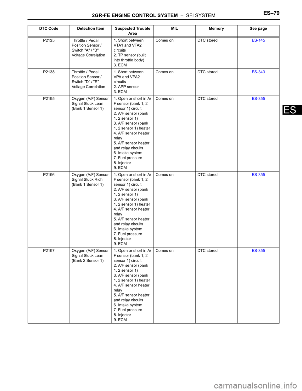
2GR-FE ENGINE CONTROL SYSTEM – SFI SYSTEMES–79
ES
P2135 Throttle / Pedal
Position Sensor /
Switch "A" / "B"
Voltage Correlation1. Short between
VTA1 and VTA2
circuits
2. TP sensor (built
into throttle body)
3. ECMComes on DTC storedES-145
P2138 Throttle / Pedal
Position Sensor /
Switch "D" / "E"
Voltage Correlation1. Short between
VPA and VPA2
circuits
2. APP sensor
3. ECMComes on DTC storedES-343
P2195 Oxygen (A/F) Sensor
Signal Stuck Lean
(Bank 1 Sensor 1)1. Open or short in A/
F sensor (bank 1, 2
sensor 1) circuit
2. A/F sensor (bank
1, 2 sensor 1)
3. A/F sensor (bank
1, 2 sensor 1) heater
4. A/F sensor heater
relay
5. A/F sensor heater
and relay circuits
6. Intake system
7. Fuel pressure
8. Injector
9. ECMComes on DTC storedES-355
P2196 Oxygen (A/F) Sensor
Signal Stuck Rich
(Bank 1 Sensor 1)1. Open or short in A/
F sensor (bank 1, 2
sensor 1) circuit
2. A/F sensor (bank
1, 2 sensor 1)
3. A/F sensor (bank
1, 2 sensor 1) heater
4. A/F sensor heater
relay
5. A/F sensor heater
and relay circuits
6. Intake system
7. Fuel pressure
8. Injector
9. ECMComes on DTC storedES-355
P2197 Oxygen (A/F) Sensor
Signal Stuck Lean
(Bank 2 Sensor 1)1. Open or short in A/
F sensor (bank 1, 2
sensor 1) circuit
2. A/F sensor (bank
1, 2 sensor 1)
3. A/F sensor (bank
1, 2 sensor 1) heater
4. A/F sensor heater
relay
5. A/F sensor heater
and relay circuits
6. Intake system
7. Fuel pressure
8. Injector
9. ECMComes on DTC storedES-355 DTC Code Detection Item Suspected Trouble
AreaMIL Memory See page
Page 386 of 3000
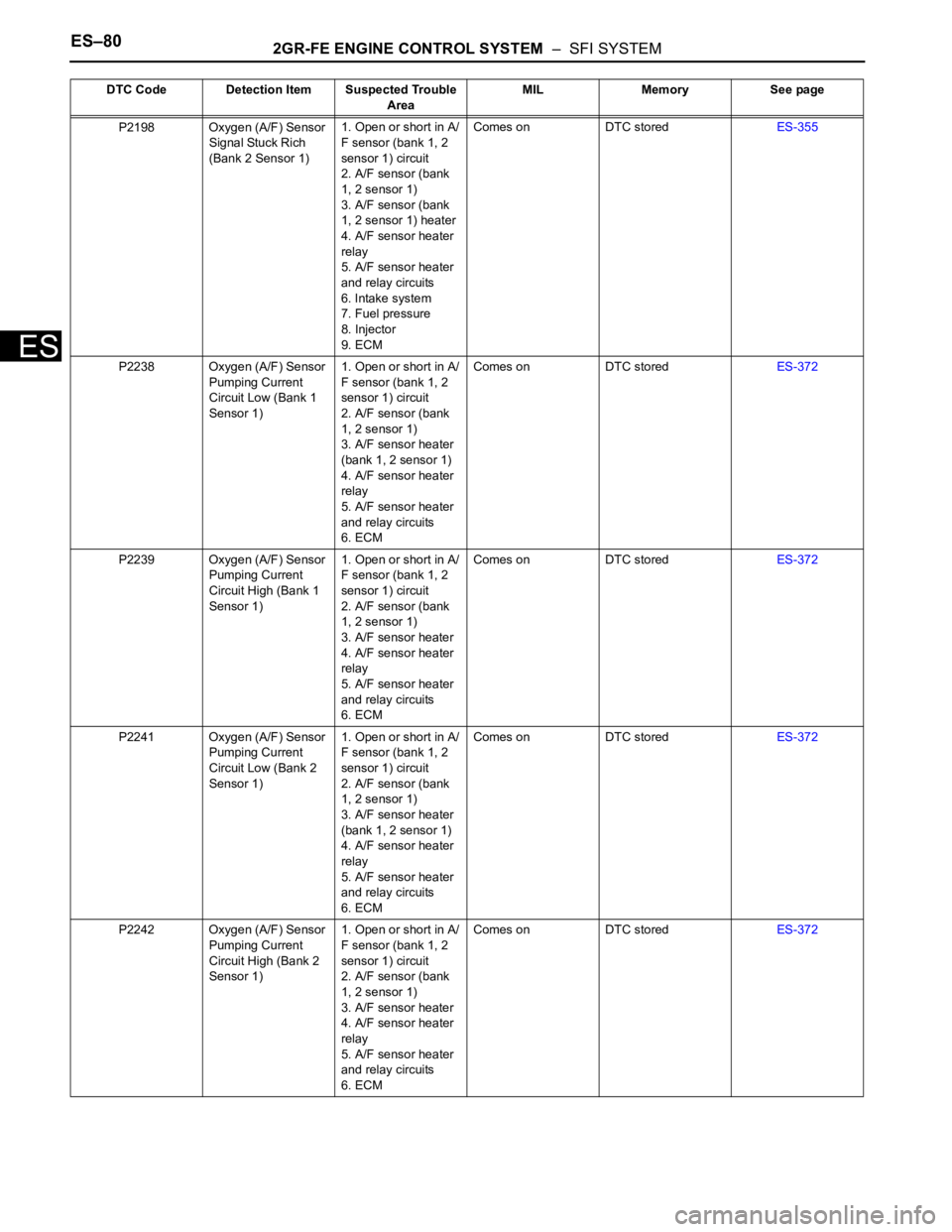
ES–802GR-FE ENGINE CONTROL SYSTEM – SFI SYSTEM
ES
P2198 Oxygen (A/F) Sensor
Signal Stuck Rich
(Bank 2 Sensor 1)1. Open or short in A/
F sensor (bank 1, 2
sensor 1) circuit
2. A/F sensor (bank
1, 2 sensor 1)
3. A/F sensor (bank
1, 2 sensor 1) heater
4. A/F sensor heater
relay
5. A/F sensor heater
and relay circuits
6. Intake system
7. Fuel pressure
8. Injector
9. ECMComes on DTC storedES-355
P2238 Oxygen (A/F) Sensor
Pumping Current
Circuit Low (Bank 1
Sensor 1)1. Open or short in A/
F sensor (bank 1, 2
sensor 1) circuit
2. A/F sensor (bank
1, 2 sensor 1)
3. A/F sensor heater
(bank 1, 2 sensor 1)
4. A/F sensor heater
relay
5. A/F sensor heater
and relay circuits
6. ECMComes on DTC storedES-372
P2239 Oxygen (A/F) Sensor
Pumping Current
Circuit High (Bank 1
Sensor 1)1. Open or short in A/
F sensor (bank 1, 2
sensor 1) circuit
2. A/F sensor (bank
1, 2 sensor 1)
3. A/F sensor heater
4. A/F sensor heater
relay
5. A/F sensor heater
and relay circuits
6. ECMComes on DTC storedES-372
P2241 Oxygen (A/F) Sensor
Pumping Current
Circuit Low (Bank 2
Sensor 1)1. Open or short in A/
F sensor (bank 1, 2
sensor 1) circuit
2. A/F sensor (bank
1, 2 sensor 1)
3. A/F sensor heater
(bank 1, 2 sensor 1)
4. A/F sensor heater
relay
5. A/F sensor heater
and relay circuits
6. ECMComes on DTC storedES-372
P2242 Oxygen (A/F) Sensor
Pumping Current
Circuit High (Bank 2
Sensor 1)1. Open or short in A/
F sensor (bank 1, 2
sensor 1) circuit
2. A/F sensor (bank
1, 2 sensor 1)
3. A/F sensor heater
4. A/F sensor heater
relay
5. A/F sensor heater
and relay circuits
6. ECMComes on DTC storedES-372 DTC Code Detection Item Suspected Trouble
AreaMIL Memory See page
Page 389 of 3000
2GR-FE ENGINE CONTROL SYSTEM – SFI SYSTEMES–83
ES
DESCRIPTION
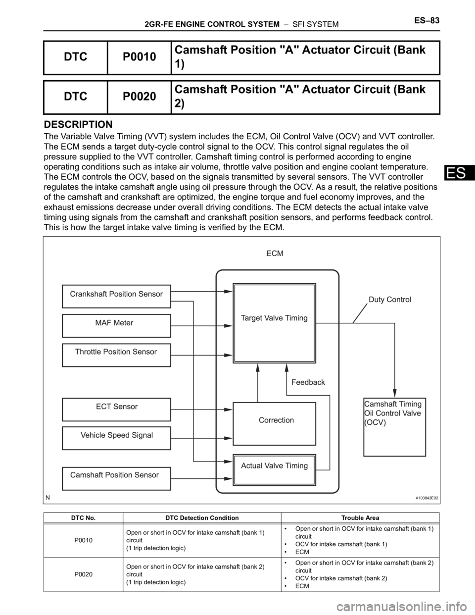
The Variable Valve Timing (VVT) system includes the ECM, Oil Control Valve (OCV) and VVT controller.
The ECM sends a target duty-cycle control signal to the OCV. This control signal regulates the oil
pressure supplied to the VVT controller. Camshaft timing control is performed according to engine
operating conditions such as intake air volume, throttle valve position and engine coolant temperature.
The ECM controls the OCV, based on the signals transmitted by several sensors. The VVT controller
regulates the intake camshaft angle using oil pressure through the OCV. As a result, the relative positions
of the camshaft and crankshaft are optimized, the engine torque and fuel economy improves, and the
exhaust emissions decrease under overall driving conditions. The ECM detects the actual intake valve
timing using signals from the camshaft and crankshaft position sensors, and performs feedback control.
This is how the target intake valve timing is verified by the ECM.
DTC P0010Camshaft Position "A" Actuator Circuit (Bank
1)
DTC P0020Camshaft Position "A" Actuator Circuit (Bank
2)
DTC No. DTC Detection Condition Trouble Area
P0010Open or short in OCV for intake camshaft (bank 1)
circuit
(1 trip detection logic)• Open or short in OCV for intake camshaft (bank 1)
circuit
• OCV for intake camshaft (bank 1)
•ECM
P0020Open or short in OCV for intake camshaft (bank 2)
circuit
(1 trip detection logic)• Open or short in OCV for intake camshaft (bank 2)
circuit
• OCV for intake camshaft (bank 2)
•ECM
A103843E02
Page 391 of 3000
2GR-FE ENGINE CONTROL SYSTEM – SFI SYSTEMES–85
ES
WIRING DIAGRAM
INSPECTION PROCEDURE
HINT:
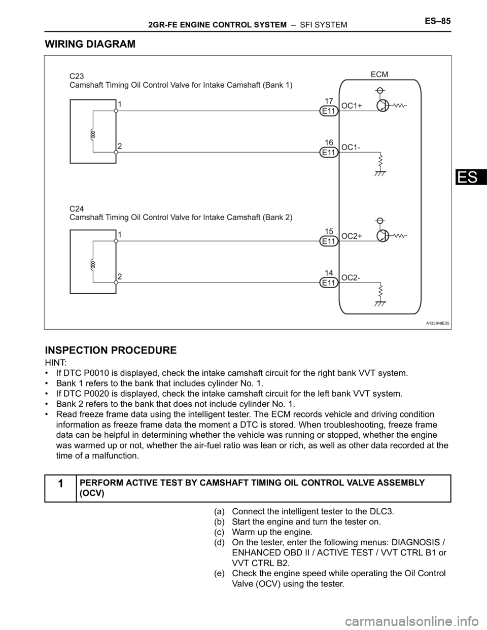
• If DTC P0010 is displayed, check the intake camshaft circuit for the right bank VVT system.
• Bank 1 refers to the bank that includes cylinder No. 1.
• If DTC P0020 is displayed, check the intake camshaft circuit for the left bank VVT system.
• Bank 2 refers to the bank that does not include cylinder No. 1.
• Read freeze frame data using the intelligent tester. The ECM records vehicle and driving condition
information as freeze frame data the moment a DTC is stored. When troubleshooting, freeze frame
data can be helpful in determining whether the vehicle was running or stopped, whether the engine
was warmed up or not, whether the air-fuel ratio was lean or rich, as well as other data recorded at the
time of a malfunction.
(a) Connect the intelligent tester to the DLC3.
(b) Start the engine and turn the tester on.
(c) Warm up the engine.
(d) On the tester, enter the following menus: DIAGNOSIS /
ENHANCED OBD II / ACTIVE TEST / VVT CTRL B1 or
VVT CTRL B2.
(e) Check the engine speed while operating the Oil Control
Valve (OCV) using the tester.
1PERFORM ACTIVE TEST BY CAMSHAFT TIMING OIL CONTROL VALVE ASSEMBLY
(OCV)
A133849E05
Page 396 of 3000

ES–902GR-FE ENGINE CONTROL SYSTEM – SFI SYSTEM
ES
HINT:
• If DTC P0011 or P0012 is displayed, check the bank 1 VVT system circuit.
• Bank 1 refers to the bank that includes cylinder No. 1.
• If DTC P0021 or P0022 is displayed, check the bank 2 VVT system circuit.
• Bank 2 refers to the bank that does not include cylinder No. 1.
• Read freeze frame data using the intelligent tester. The ECM records vehicle and driving condition
information as freeze frame data the moment a DTC is stored. When troubleshooting, freeze frame
data can be helpful in determining whether the vehicle was running or stopped, whether the engine
was warmed up or not, whether the air-fuel ratio was lean or rich, as well as other data recorded at the
time of a malfunction.
(a) Connect the intelligent tester to the DLC3.
(b) Turn the ignition switch to the ON position and turn the
tester on.
(c) Select the following menu items: DIAGNOSIS /
ENHANCED OBD II / DTC INFO / CURRENT CODES.
(d) Read the DTCs.
Result
HINT:
If any DTCs other than P0011, P0012, P0021 or P0022
are output, troubleshoot those DTCs first.
B
A
(a) Connect the intelligent tester to the DLC3.
(b) Start the engine and turn the tester on.
(c) Warm up the engine.
(d) Select the following menu items on the tester:
DIAGNOSIS / ENHANCED OBD II / ACTIVE TEST /
VVT CTRL B1.
(e) Check the engine speed while operating the Oil Control
Valve (OCV) using the tester.
OK
NG
OK
1CHECK ANY OTHER DTCS OUTPUT (IN ADDITION TO DTC P0011, P0012, P0021 OR
P0022)
Display (DTC Output) Proceed to
P0011, P0012, P0021 or P0022 A
P0011, P0012, P0021 or P0022 and other DTCs B
GO TO DTC CHART (See page ES-56)
2PERFORM ACTIVE TEST BY INTELLIGENT TESTER (OPERATE OCV)
Tester Operation Specified Condition
OCV OFF Normal engine idle speed
OCV ON Engine idles roughly or stalls (soon after OCV switched from OFF to ON)
Go to step 4
Page 401 of 3000
2GR-FE ENGINE CONTROL SYSTEM – SFI SYSTEMES–95
ES
DESCRIPTION
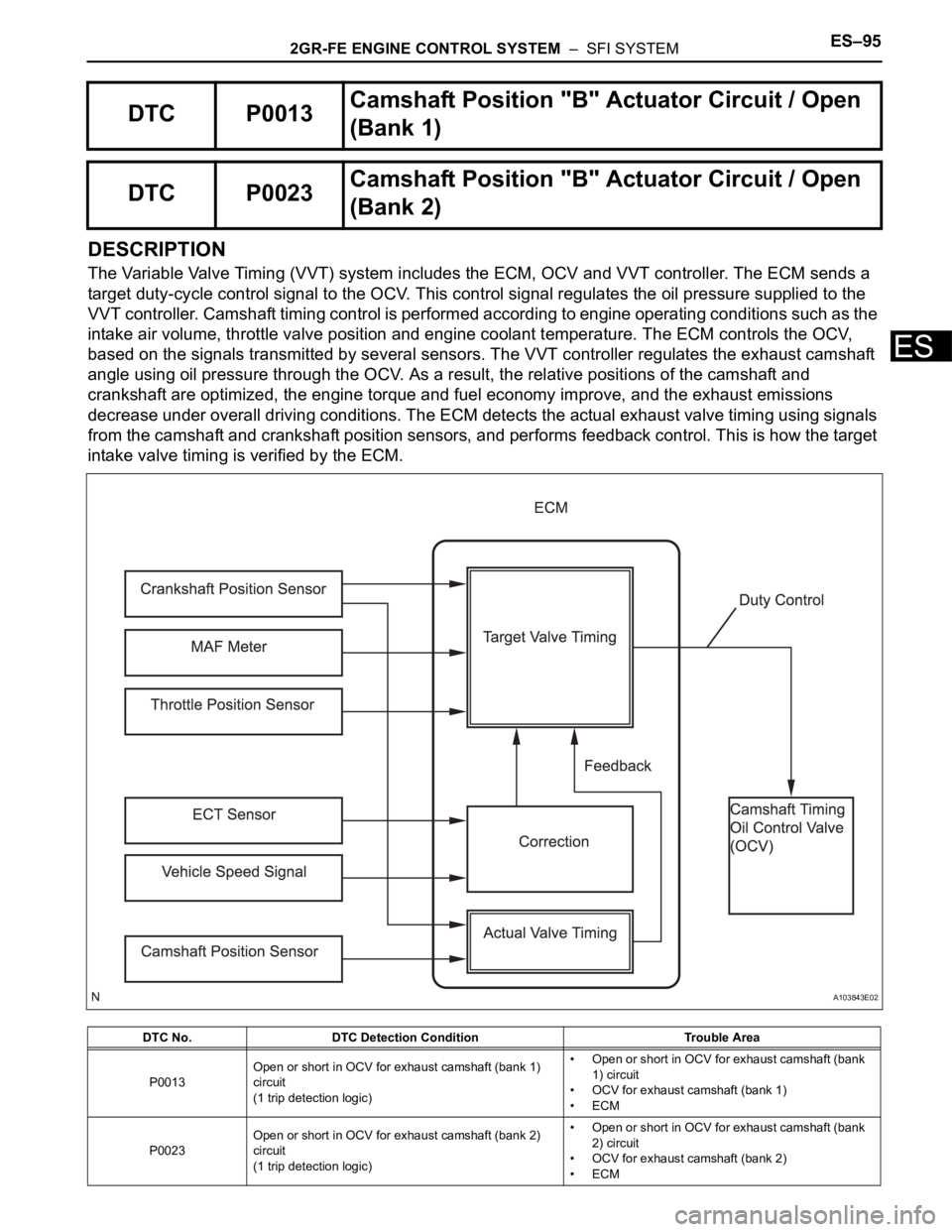
The Variable Valve Timing (VVT) system includes the ECM, OCV and VVT controller. The ECM sends a
target duty-cycle control signal to the OCV. This control signal regulates the oil pressure supplied to the
VVT controller. Camshaft timing control is performed according to engine operating conditions such as the
intake air volume, throttle valve position and engine coolant temperature. The ECM controls the OCV,
based on the signals transmitted by several sensors. The VVT controller regulates the exhaust camshaft
angle using oil pressure through the OCV. As a result, the relative positions of the camshaft and
crankshaft are optimized, the engine torque and fuel economy improve, and the exhaust emissions
decrease under overall driving conditions. The ECM detects the actual exhaust valve timing using signals
from the camshaft and crankshaft position sensors, and performs feedback control. This is how the target
intake valve timing is verified by the ECM.
DTC P0013Camshaft Position "B" Actuator Circuit / Open
(Bank 1)
DTC P0023Camshaft Position "B" Actuator Circuit / Open
(Bank 2)
DTC No. DTC Detection Condition Trouble Area
P0013Open or short in OCV for exhaust camshaft (bank 1)
circuit
(1 trip detection logic)• Open or short in OCV for exhaust camshaft (bank
1) circuit
• OCV for exhaust camshaft (bank 1)
•ECM
P0023Open or short in OCV for exhaust camshaft (bank 2)
circuit
(1 trip detection logic)• Open or short in OCV for exhaust camshaft (bank
2) circuit
• OCV for exhaust camshaft (bank 2)
•ECM
A103843E02