Page 31 of 3000
EM–322GR-FE ENGINE MECHANICAL – ENGINE ASSEMBLY
EM
(c) Remove the clip and disconnect the transmission
control cable assembly from the control cable
bracket.
(d) Disconnect the control cable from the control cable
clamp.
38. DISCONNECT RETURN TUBE SUB-ASSEMBLY
(a) Using pliers, grip the claws of the 2 clips and slide
the 2 clips to disconnect the 2 return tube sub-
assemblies.
(b) Drain the power steering fluid.
NOTICE:
Take care not to damage the hose protector.
39. DISCONNECT NO. 1 OIL RESERVOIR TO PUMP
HOSE
(a) Using pliers, grip the claws of the clip and slide the
clip to disconnect the No. 1 oil reservoir to pump
hose from the oil reservoir tank.
40. DISCONNECT ENGINE WIRE
(a) Disconnect the engine wire from the engine room
junction block.
(1) Remove the nut and separate the wire harness.
(2) Using a screwdriver, unlock the engine room
junction block. Pull the engine room junction
block upward.
C089134E01
C090579
A163268
A155029
A155037
Page 34 of 3000
2GR-FE ENGINE MECHANICAL – ENGINE ASSEMBLYEM–35
EM
(b) Remove the 6 bolts, 2 nuts, and frame side rail
plates RH and LH.
(c) Remove the 6 bolts, 2 nuts, and front suspension
member brace rear RH and LH.
(d) Operate the engine lifter, then remove the engine
assembly from the vehicle.
NOTICE:
Make sure that the engine is clear of all wiring
and hoses.
62. REMOVE V-RIBBED BELT (See page EM-6)
63. REMOVE VANE PUMP ASSEMBLY
(a) Disconnect the power steering oil pressure switch
connector.
(b) Remove the 2 nuts.
(c) Loosen the bolt A.
(d) Remove the bolt B.
(e) Remove the bolt A and vane pump assembly.
64. REMOVE FRONT STABILIZER BAR (for 4WD)
HINT:
See page SP-35.
65. REMOVE POWER STEERING LINK
(a) Remove the 2 bolts and power steering link with
vane pump.
A162364
A162363
A155024
A139216E01
Page 191 of 3000
POWER STEERING – VANE PUMPPS–9
PS
REMOVAL
1. DRAIN POWER STEERING FLUID
2. REMOVE FRONT WHEEL RH
3. REMOVE FRONT FENDER APRON SEAL RH (See
page EM-26)
4. REMOVE FAN AND GENERATOR V BELT (See page
EM-6)
5. DISCONNECT NO. 1 FLUID RESERVOIR TO PUMP
HOSE
(a) Slide the clip and disconnect the No. 1 fluid
reservoir to pump hose from the vane pump
assembly.
6. DISCONNECT PRESSURE FEED TUBE ASSEMBLY
(a) Remove the union bolt and disconnect the pressure
feed tube assembly from the vane pump assembly.
(b) Remove the gasket from the pressure feed tube
assembly.
7. DISCONNECT POWER STEERING FLUID PRESSURE
SWITCH CONNECTOR
(a) Disconnect the power steering fluid pressure switch
connector.
C133174E02
C161546
C161547
Page 192 of 3000
PS–10POWER STEERING – VANE PUMP
PS
8. REMOVE VANE PUMP ASSEMBLY
(a) Using SST, loosen bolt (A) and remove bolt (B), and
then remove the vane pump assembly.
SST 09249-63010
(b) Remove the bolt from the vane pump assembly.
DISASSEMBLY
1. HOLD VANE PUMP ASSEMBLY
(a) Using SST, hold the vane pump assembly in a vise.
SST 09630-00014 (09631-00132)
2. REMOVE POWER STEERING SUCTION PORT UNION
(a) Remove the bolt and the power steering suction port
union from the vane pump front housing.
(b) Using a screwdriver, remove the O-ring from the
power steering suction port union.
3. REMOVE POWER STEERING FLUID PRESSURE
SWITCH
NOTICE:
Perform this procedure only when the power
steering fluid pressure switch is replaced.
C158999E01
C135238
C141305E01
C133179
Page 193 of 3000
POWER STEERING – VANE PUMPPS–11
PS
(a) Remove the power steering fluid pressure switch
from the vane pump front housing.
4. REMOVE FLOW CONTROL VALVE ASSEMBLY
(a) Remove the pressure port union from the vane
pump front housing.
(b) Remove the O-ring from the pressure port union.
(c) Remove the flow control valve assembly and the
flow control valve compression spring from the vane
pump front housing.
5. REMOVE VANE PUMP REAR HOUSING
(a) Remove the 4 bolts and vane pump rear housing
from the vane pump front housing.
(b) Using a screwdriver, remove the O-ring from the
vane pump rear housing.
HINT:
Tape the screwdriver tip before use.
6. REMOVE VANE PUMP SHAFT WITH PULLEY
(a) Using 2 screwdrivers, remove the vane pump shaft
snap ring from the vane pump shaft with pulley.
(b) Remove the vane pump shaft with pulley.
C133180
C158998
C107024
C107025E02
C057767
Page 194 of 3000
PS–12POWER STEERING – VANE PUMP
PS
7. REMOVE VANE PUMP ROTOR
(a) Remove the 10 vane pump plates.
(b) Remove the vane pump rotor.
8. REMOVE VANE PUMP CAM RING
(a) Remove the vane pump cam ring from the vane
pump front housing.
9. REMOVE VANE PUMP FRONT SIDE PLATE
(a) Remove the vane pump front side plate from the
vane pump front housing.
(b) Using a screwdriver, remove the O-ring from the
vane pump front side plate.
HINT:
Tape the screwdriver tip before use.
(c) Remove the O-ring from the vane pump front
housing.
C114697
C114698
C114699
C107029E02
C114700
Page 195 of 3000

POWER STEERING – VANE PUMPPS–13
PS
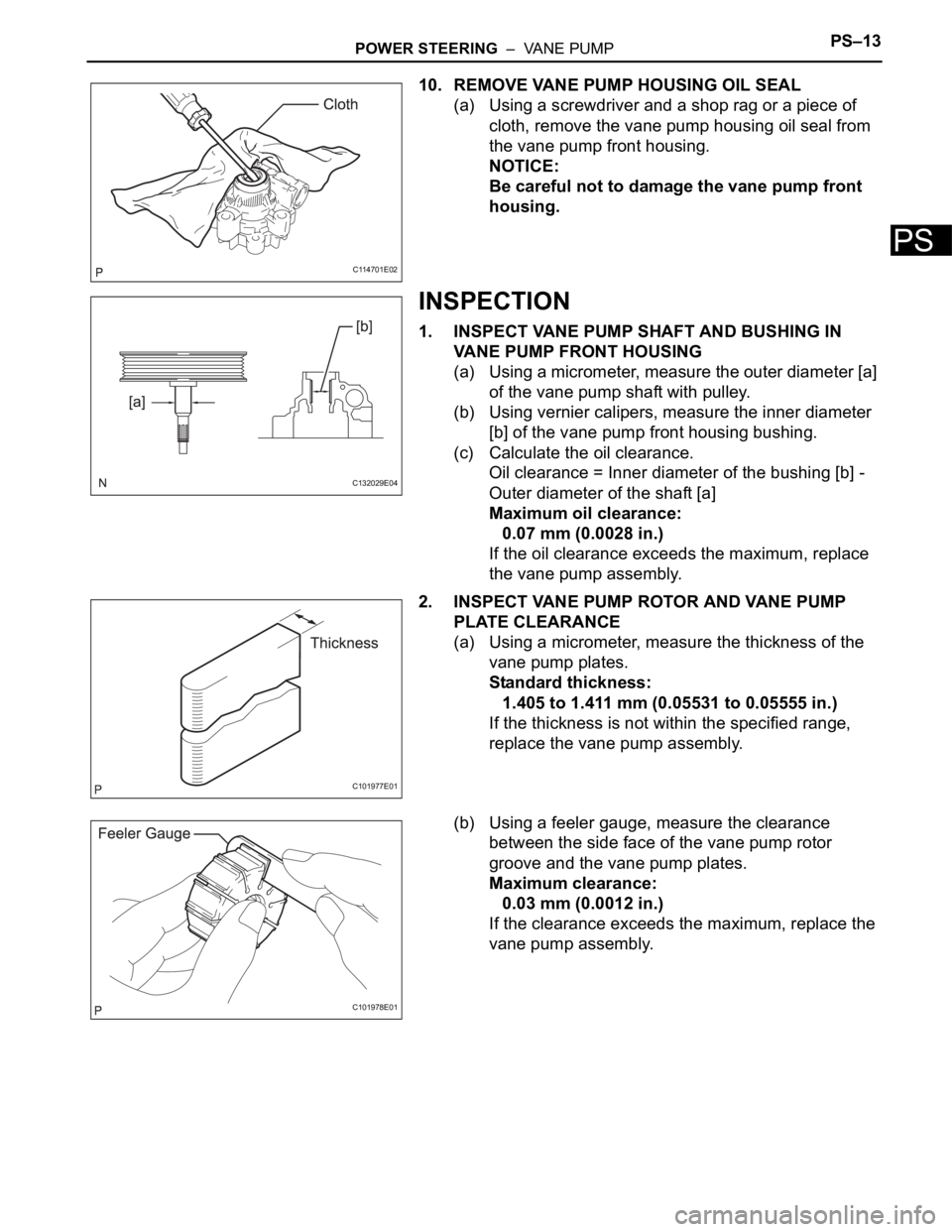
10. REMOVE VANE PUMP HOUSING OIL SEAL
(a) Using a screwdriver and a shop rag or a piece of
cloth, remove the vane pump housing oil seal from
the vane pump front housing.
NOTICE:
Be careful not to damage the vane pump front
housing.
INSPECTION
1. INSPECT VANE PUMP SHAFT AND BUSHING IN
VANE PUMP FRONT HOUSING
(a) Using a micrometer, measure the outer diameter [a]
of the vane pump shaft with pulley.
(b) Using vernier calipers, measure the inner diameter
[b] of the vane pump front housing bushing.
(c) Calculate the oil clearance.
Oil clearance = Inner diameter of the bushing [b] -
Outer diameter of the shaft [a]
Maximum oil clearance:
0.07 mm (0.0028 in.)
If the oil clearance exceeds the maximum, replace
the vane pump assembly.
2. INSPECT VANE PUMP ROTOR AND VANE PUMP
PLATE CLEARANCE
(a) Using a micrometer, measure the thickness of the
vane pump plates.
Standard thickness:
1.405 to 1.411 mm (0.05531 to 0.05555 in.)
If the thickness is not within the specified range,
replace the vane pump assembly.
(b) Using a feeler gauge, measure the clearance
between the side face of the vane pump rotor
groove and the vane pump plates.
Maximum clearance:
0.03 mm (0.0012 in.)
If the clearance exceeds the maximum, replace the
vane pump assembly.
C114701E02
C132029E04
C101977E01
C101978E01
Page 196 of 3000

PS–14POWER STEERING – VANE PUMP
PS
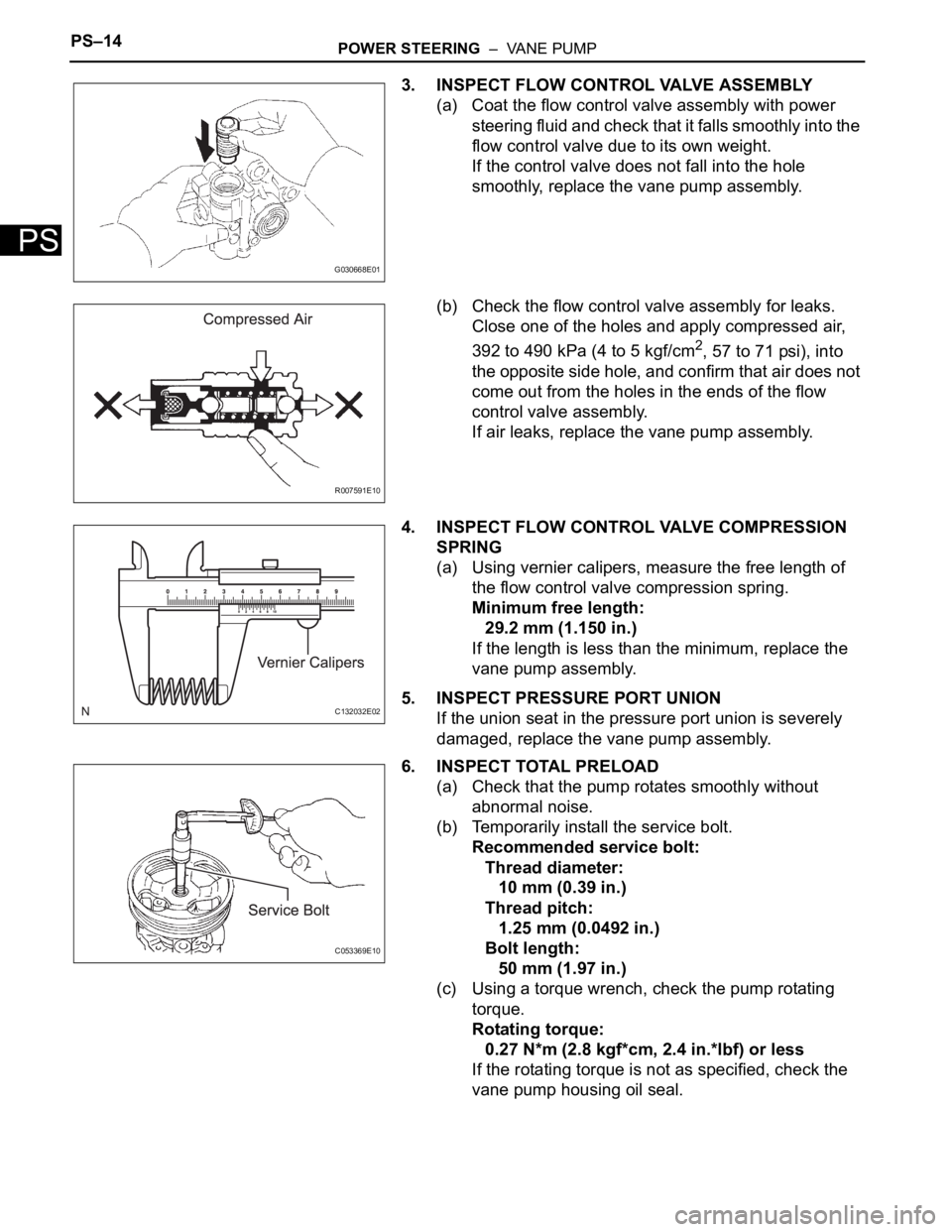
3. INSPECT FLOW CONTROL VALVE ASSEMBLY
(a) Coat the flow control valve assembly with power
steering fluid and check that it falls smoothly into the
flow control valve due to its own weight.
If the control valve does not fall into the hole
smoothly, replace the vane pump assembly.
(b) Check the flow control valve assembly for leaks.
Close one of the holes and apply compressed air,
392 to 490 kPa (4 to 5 kgf/cm
2, 57 to 71 psi), into
the opposite side hole, and confirm that air does not
come out from the holes in the ends of the flow
control valve assembly.
If air leaks, replace the vane pump assembly.
4. INSPECT FLOW CONTROL VALVE COMPRESSION
SPRING
(a) Using vernier calipers, measure the free length of
the flow control valve compression spring.
Minimum free length:
29.2 mm (1.150 in.)
If the length is less than the minimum, replace the
vane pump assembly.
5. INSPECT PRESSURE PORT UNION
If the union seat in the pressure port union is severely
damaged, replace the vane pump assembly.
6. INSPECT TOTAL PRELOAD
(a) Check that the pump rotates smoothly without
abnormal noise.
(b) Temporarily install the service bolt.
Recommended service bolt:
Thread diameter:
10 mm (0.39 in.)
Thread pitch:
1.25 mm (0.0492 in.)
Bolt length:
50 mm (1.97 in.)
(c) Using a torque wrench, check the pump rotating
torque.
Rotating torque:
0.27 N*m (2.8 kgf*cm, 2.4 in.*lbf) or less
If the rotating torque is not as specified, check the
vane pump housing oil seal.
G030668E01
R007591E10
C132032E02
C053369E10