2007 TOYOTA SIENNA water pump
[x] Cancel search: water pumpPage 40 of 3000
2GR-FE ENGINE MECHANICAL – ENGINE ASSEMBLYEM–41
EM
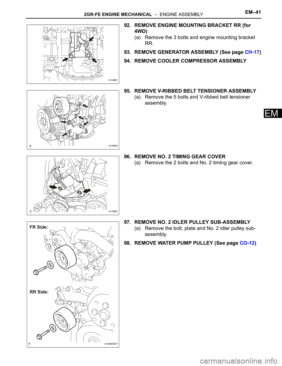
92. REMOVE ENGINE MOUNTING BRACKET RR (for
4WD)
(a) Remove the 3 bolts and engine mounting bracket
RR.
93. REMOVE GENERATOR ASSEMBLY (See page CH-17)
94. REMOVE COOLER COMPRESSOR ASSEMBLY
95. REMOVE V-RIBBED BELT TENSIONER ASSEMBLY
(a) Remove the 5 bolts and V-ribbed belt tensioner
assembly.
96. REMOVE NO. 2 TIMING GEAR COVER
(a) Remove the 2 bolts and No. 2 timing gear cover.
97. REMOVE NO. 2 IDLER PULLEY SUB-ASSEMBLY
(a) Remove the bolt, plate and No. 2 idler pulley sub-
assembly.
98. REMOVE WATER PUMP PULLEY (See page CO-12)
A143881
A129644
A132987
A129645E01
Page 57 of 3000

IN–50INTRODUCTION – TERMS
IN
GLOSSARY OF SAE AND TOYOTA
TERMS
This glossary lists all SAE-J1930 terms and abbreviations
used in this manual in compliance with SAE
recommendations, as well as their TOYOTA equivalents.
SAE
ABBREVIATIONSSAE TERMSTOYOTA TERMS
( )-ABBREVIATIONS
A/C Air Conditioning Air Conditioner
ACL Air Cleaner Air Cleaner, A/CL
AIR Secondary Air Injection Air Injection (AI)
AP Accelerator Pedal -
B+ Battery Positive Voltage +B, Battery Voltage
BARO Barometric Pressure HAC
CAC Charge Air Cooler Intercooler
CARB Carburetor Carburetor
CFI Continuous Fuel Injection -
CKP Crankshaft Position Crank Angle
CL Closed Loop Closed Loop
CMP Camshaft Position Cam Angle
CPP Clutch Pedal Position -
CTOX Continuous Trap Oxidizer -
CTP Closed Throttle Position LL ON, Idle ON
DFI Direct Fuel Injection Direct Injection (DI./INJ)
DI Distributor Ignition -
DLC3 Data Link Connector 3 OBD II Diagnostic Connector
DTC Diagnostic Trouble Code Diagnostic Trouble Code
DTM Diagnostic Test Mode -
ECL Engine Coolant Level -
ECM Engine Control Module Engine Electronic Control Unit (ECU)
ECT Engine Coolant Temperature Coolant Temperature, Water Temperature (THW)
EEPROM Electrically Erasable Programmable Read Only MemoryElectrically Erasable Programmable Read Only
Memory (EEPROM), Erasable Programmable Read
Only Memory (EPROM)
EFE Early Fuel Evaporation Cold Mixture Heater (CMH), Heat Control Valve (HCV)
EGR Exhaust Gas Recirculation Exhaust Gas Recirculation (EGR)
EI Electronic Ignition Distributorless Ignition (DLI)
EM Engine Modification Engine Modification (EM)
EPROM Erasable Programmable Read Only Memory Programmable Read Only Memory (PROM)
EVAP Evaporative Emission Evaporative Emission Control (EVAP)
FC Fan Control -
FEEPROMFlash Electrically Erasable Programmable Read Only
Memory-
FEPROM Flash Erasable Programmable Read Only Memory -
FF Flexible Fuel -
FP Fuel Pump Fuel Pump
GEN Generator Alternator
GND Ground Ground (GND)
HO2S Heated Oxygen SensorHeated Oxygen Sensor (HO
2S)
IAC Idle Air Control Idle Speed Control (ISC)
IAT Intake Air Temperature Intake or Inlet Air Temperature
ICM Ignition Control Module -
Page 78 of 3000
2GR-FE LUBRICATION – OIL PUMPLU–11
LU
REMOVAL
1. REMOVE ENGINE ASSEMBLY WITH TRANSAXLE
HINT:
See page EM-26
2. REMOVE OIL LEVEL GAUGE GUIDE SUB-
ASSEMBLY (See page EM-39)
3. REMOVE NO. 1 OIL PIPE (See page EM-77)
4. REMOVE OIL PIPE (See page EM-77)
5. REMOVE CRANKSHAFT PULLEY (See page EM-79)
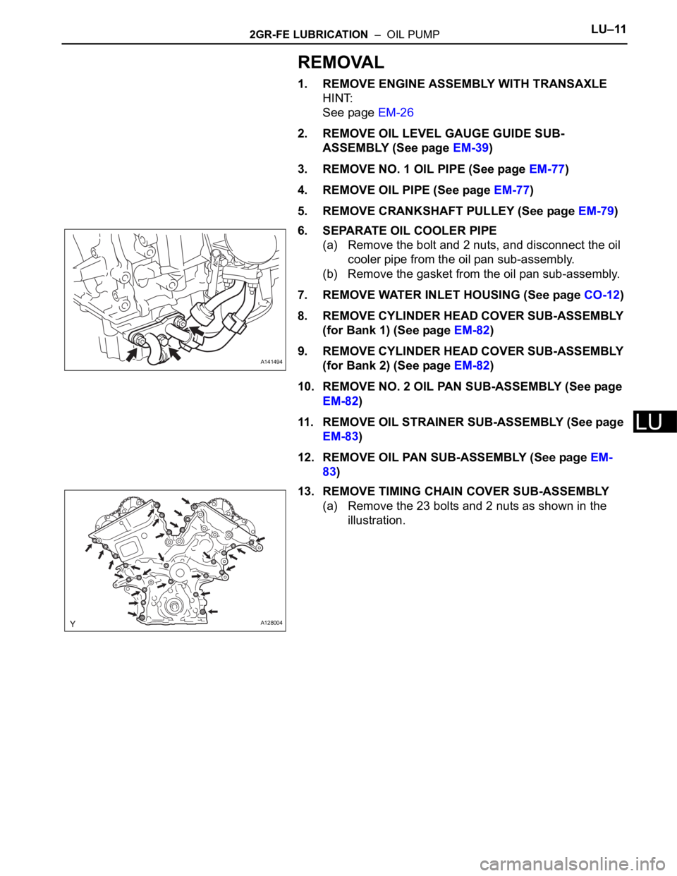
6. SEPARATE OIL COOLER PIPE
(a) Remove the bolt and 2 nuts, and disconnect the oil
cooler pipe from the oil pan sub-assembly.
(b) Remove the gasket from the oil pan sub-assembly.
7. REMOVE WATER INLET HOUSING (See page CO-12)
8. REMOVE CYLINDER HEAD COVER SUB-ASSEMBLY
(for Bank 1) (See page EM-82)
9. REMOVE CYLINDER HEAD COVER SUB-ASSEMBLY
(for Bank 2) (See page EM-82)
10. REMOVE NO. 2 OIL PAN SUB-ASSEMBLY (See page
EM-82)
11. REMOVE OIL STRAINER SUB-ASSEMBLY (See page
EM-83)
12. REMOVE OIL PAN SUB-ASSEMBLY (See page EM-
83)
13. REMOVE TIMING CHAIN COVER SUB-ASSEMBLY
(a) Remove the 23 bolts and 2 nuts as shown in the
illustration.
A141494
A128004
Page 197 of 3000
SS–10SERVICE SPECIFICATIONS – 2GR-FE ENGINE MECHANICAL
SS
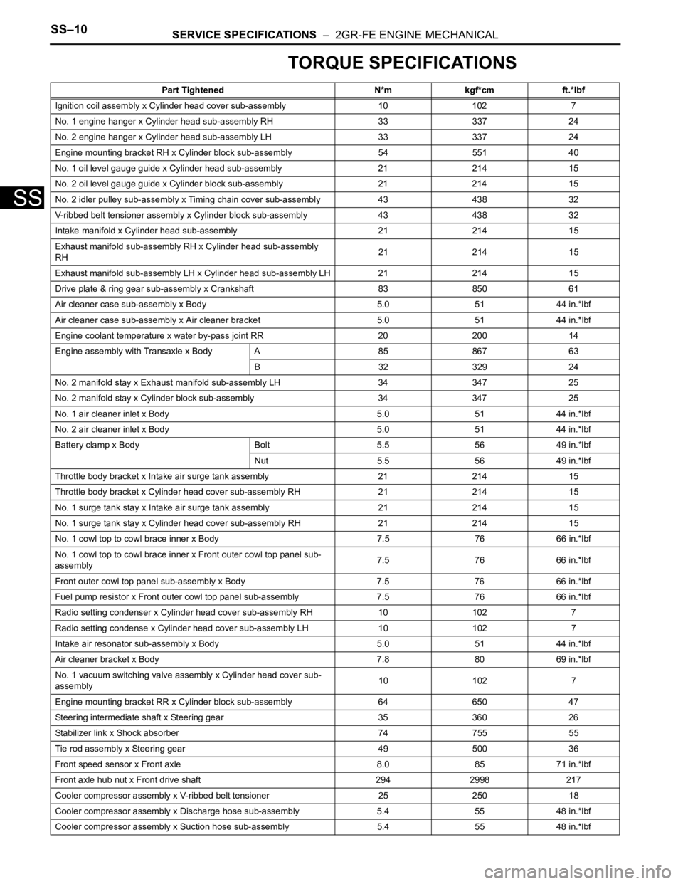
TORQUE SPECIFICATIONS
Part Tightened N*m kgf*cm ft.*lbf
Ignition coil assembly x Cylinder head cover sub-assembly 10 102 7
No. 1 engine hanger x Cylinder head sub-assembly RH 33 337 24
No. 2 engine hanger x Cylinder head sub-assembly LH 33 337 24
Engine mounting bracket RH x Cylinder block sub-assembly 54 551 40
No. 1 oil level gauge guide x Cylinder head sub-assembly 21 214 15
No. 2 oil level gauge guide x Cylinder block sub-assembly 21 214 15
No. 2 idler pulley sub-assembly x Timing chain cover sub-assembly 43 438 32
V-ribbed belt tensioner assembly x Cylinder block sub-assembly 43 438 32
Intake manifold x Cylinder head sub-assembly 21 214 15
Exhaust manifold sub-assembly RH x Cylinder head sub-assembly
RH21 214 15
Exhaust manifold sub-assembly LH x Cylinder head sub-assembly LH 21 214 15
Drive plate & ring gear sub-assembly x Crankshaft 83 850 61
Air cleaner case sub-assembly x Body 5.0 51 44 in.*lbf
Air cleaner case sub-assembly x Air cleaner bracket 5.0 51 44 in.*lbf
Engine coolant temperature x water by-pass joint RR 20 200 14
Engine assembly with Transaxle x Body A 85 867 63
B 32 329 24
No. 2 manifold stay x Exhaust manifold sub-assembly LH 34 347 25
No. 2 manifold stay x Cylinder block sub-assembly 34 347 25
No. 1 air cleaner inlet x Body 5.0 51 44 in.*lbf
No. 2 air cleaner inlet x Body 5.0 51 44 in.*lbf
Battery clamp x Body Bolt 5.5 56 49 in.*lbf
Nut 5.5 56 49 in.*lbf
Throttle body bracket x Intake air surge tank assembly 21 214 15
Throttle body bracket x Cylinder head cover sub-assembly RH 21 21415
No. 1 surge tank stay x Intake air surge tank assembly 21 214 15
No. 1 surge tank stay x Cylinder head cover sub-assembly RH 21 21415
No. 1 cowl top to cowl brace inner x Body 7.5 76 66 in.*lbf
No. 1 cowl top to cowl brace inner x Front outer cowl top panel sub-
assembly7.5 76 66 in.*lbf
Front outer cowl top panel sub-assembly x Body 7.5 76 66 in.*lbf
Fuel pump resistor x Front outer cowl top panel sub-assembly 7.576 66 in.*lbf
Radio setting condenser x Cylinder head cover sub-assembly RH 10102 7
Radio setting condense x Cylinder head cover sub-assembly LH 10 102 7
Intake air resonator sub-assembly x Body 5.0 51 44 in.*lbf
Air cleaner bracket x Body 7.8 80 69 in.*lbf
No. 1 vacuum switching valve assembly x Cylinder head cover sub-
assembly10 102 7
Engine mounting bracket RR x Cylinder block sub-assembly 64 650 47
Steering intermediate shaft x Steering gear 35 360 26
Stabilizer link x Shock absorber 74 755 55
Tie rod assembly x Steering gear 49 500 36
Front speed sensor x Front axle 8.0 85 71 in.*lbf
Front axle hub nut x Front drive shaft 294 2998 217
Cooler compressor assembly x V-ribbed belt tensioner 25 250 18
Cooler compressor assembly x Discharge hose sub-assembly 5.4 55 48 in.*lbf
Cooler compressor assembly x Suction hose sub-assembly 5.4 55 48 in.*lbf
Page 198 of 3000

SERVICE SPECIFICATIONS – 2GR-FE ENGINE MECHANICALSS–11
SS
Engine mounting control bracket x No. 1 engine
front mounting bracket LH
Bolt A 44 450 32
Bolt B 38 388 28
Nut 23 235 17
Engine assembly with Transaxle x Front frame
assemblyNut A 87 887 64
Nut B 95 969 70
Engine assembly with Transaxle x engine mounting insulator RR 78795 58
Drive shaft bearing bracket x Cylinder block sub-assembly 64 650 47
No. 2 exhaust manifold heat insulator x Exhaust manifold sub-
assembly LH8.5 87 75 in.*lbf
Engine oil pressure switch assembly x Oil pan sub-assembly 21 21415
No. 2 engine mounting stay RH x Intake manifold 21 214 15
No. 2 timing gear cover x Chain cover sub-assembly 6.0 61 53 in.*lbf
No. 1 engine front mounting bracket LH x Chain cover 54 551 40
Camshaft bearing cap x Camshaft housing 1st 10 102 7
2nd 16 163 12
Camshaft housing x Cylinder head sub-assembly 28 286 21
Chain tensioner No. 1 x Cylinder head sub-assembly 10 102 7
Chain tensioner No. 2 x Cylinder head sub-assembly 21 214 15
Chain tensioner No. 3 x Cylinder head sub-assembly 21 214 15
Camshaft timing gear assembly x Camshaft 100 1,020 74
Camshaft timing exhaust gear assembly x Camshaft 100 1,020 74
Engine rear oil seal retainer x Cylinder block sub-assembly 10 1027
Knock control sensor x Cylinder block sub-assembly 20 204 15
Water inlet pipe x Cylinder block sub-assembly 10 102 7
Cylinder head sub-assembly RH x Cylinder
block sub-assembly1st 36 367 27
2nd Turn 90
Turn 90Turn 90
3nd Turn 90Turn 90Turn 90
Cylinder head sub-assembly LH x Cylinder
block sub-assembly
Recessed head 1st 36 367 27
2nd Turn 90
Turn 90Turn 90
3nd Turn 90Turn 90Turn 90
14 mm (0.55 in.)
head30 306 22
Chain vibration damper No. 1 x Cylinder block sub-assembly 23 23017
No. 2 Idle gear shaft x Cylinder block sub-assembly 60 612 44
Timing chain cover plate x Timing chain cover sub-assembly 9.1 9381 in.*lbf
Timing chain cover sub-assembly x Cylinder
head and block
Areas 1: Bolt 21 214 15
Areas 2: Bolt 21 214 15
Areas 3: Bolt and
Nut21 214 15
Areas 4: Bolt A 43 438 32
Areas 4: Except
Bolt A21 214 15
Water pump assembly x Timing chain cover sub-assembly 9.1 93 81 in.*lbf
Oil pan baffle plate x Cylinder block sub-assembly 10 102 7
Oil pan stud bolt x Cylinder block and timing chain cover sub-
assembly10 102 7
Oil pan stud bolt x No. 2 oil pan sub-assembly 4.0 41 35 in.*lbf
Oil cooler stud bolt x Oil pan sub-assembly 10 102 7Part Tightened N*m kgf*cm ft.*lbf
Page 577 of 3000
ES–2842GR-FE ENGINE CONTROL SYSTEM – SFI SYSTEM
ES
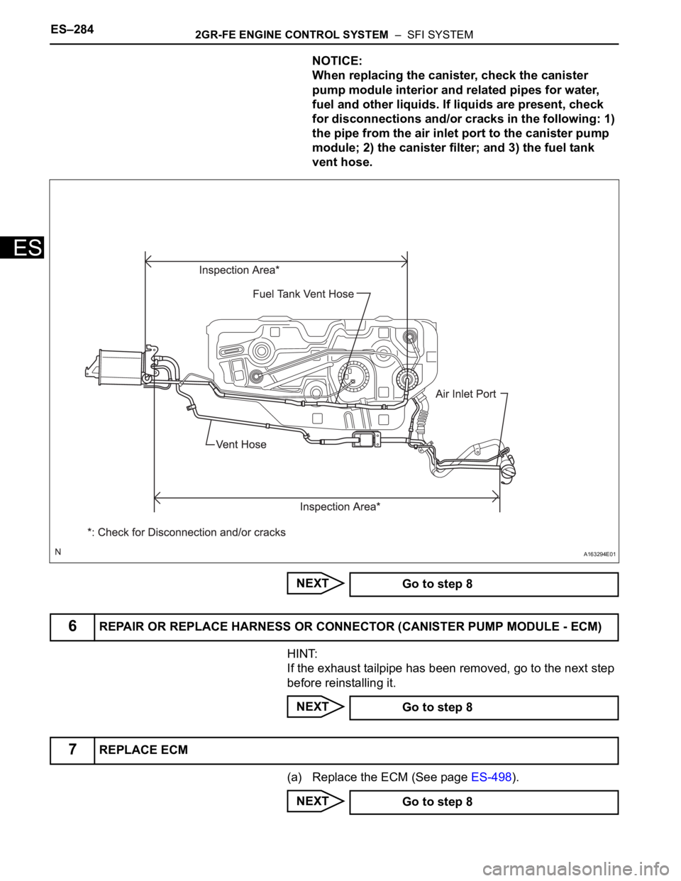
NOTICE:
When replacing the canister, check the canister
pump module interior and related pipes for water,
fuel and other liquids. If liquids are present, check
for disconnections and/or cracks in the following: 1)
the pipe from the air inlet port to the canister pump
module; 2) the canister filter; and 3) the fuel tank
vent hose.
NEXT
HINT:
If the exhaust tailpipe has been removed, go to the next step
before reinstalling it.
NEXT
(a) Replace the ECM (See page ES-498).
NEXT
A163294E01
Go to step 8
6REPAIR OR REPLACE HARNESS OR CONNECTOR (CANISTER PUMP MODULE - ECM)
Go to step 8
7REPLACE ECM
Go to step 8
Page 727 of 3000
2GR-FE ENGINE CONTROL SYSTEM – SFI SYSTEMES–441
ES
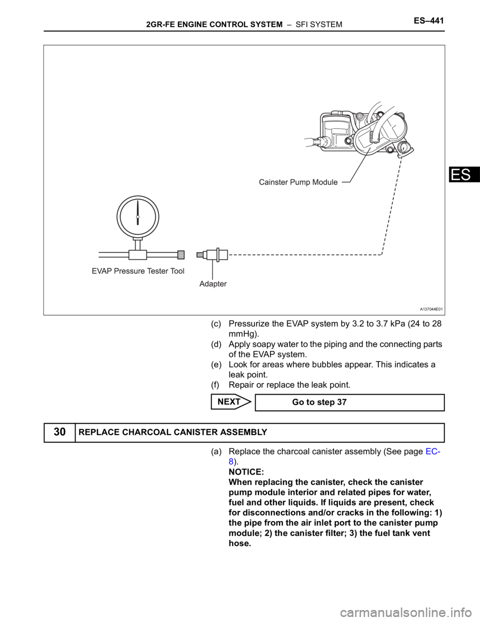
(c) Pressurize the EVAP system by 3.2 to 3.7 kPa (24 to 28
mmHg).
(d) Apply soapy water to the piping and the connecting parts
of the EVAP system.
(e) Look for areas where bubbles appear. This indicates a
leak point.
(f) Repair or replace the leak point.
NEXT
(a) Replace the charcoal canister assembly (See page EC-
8).
NOTICE:
When replacing the canister, check the canister
pump module interior and related pipes for water,
fuel and other liquids. If liquids are present, check
for disconnections and/or cracks in the following: 1)
the pipe from the air inlet port to the canister pump
module; 2) the canister filter; 3) the fuel tank vent
hose.
A137044E01
Go to step 37
30REPLACE CHARCOAL CANISTER ASSEMBLY
Page 862 of 3000
2GR-FE ENGINE MECHANICAL – ENGINE ASSEMBLYEM–45
EM
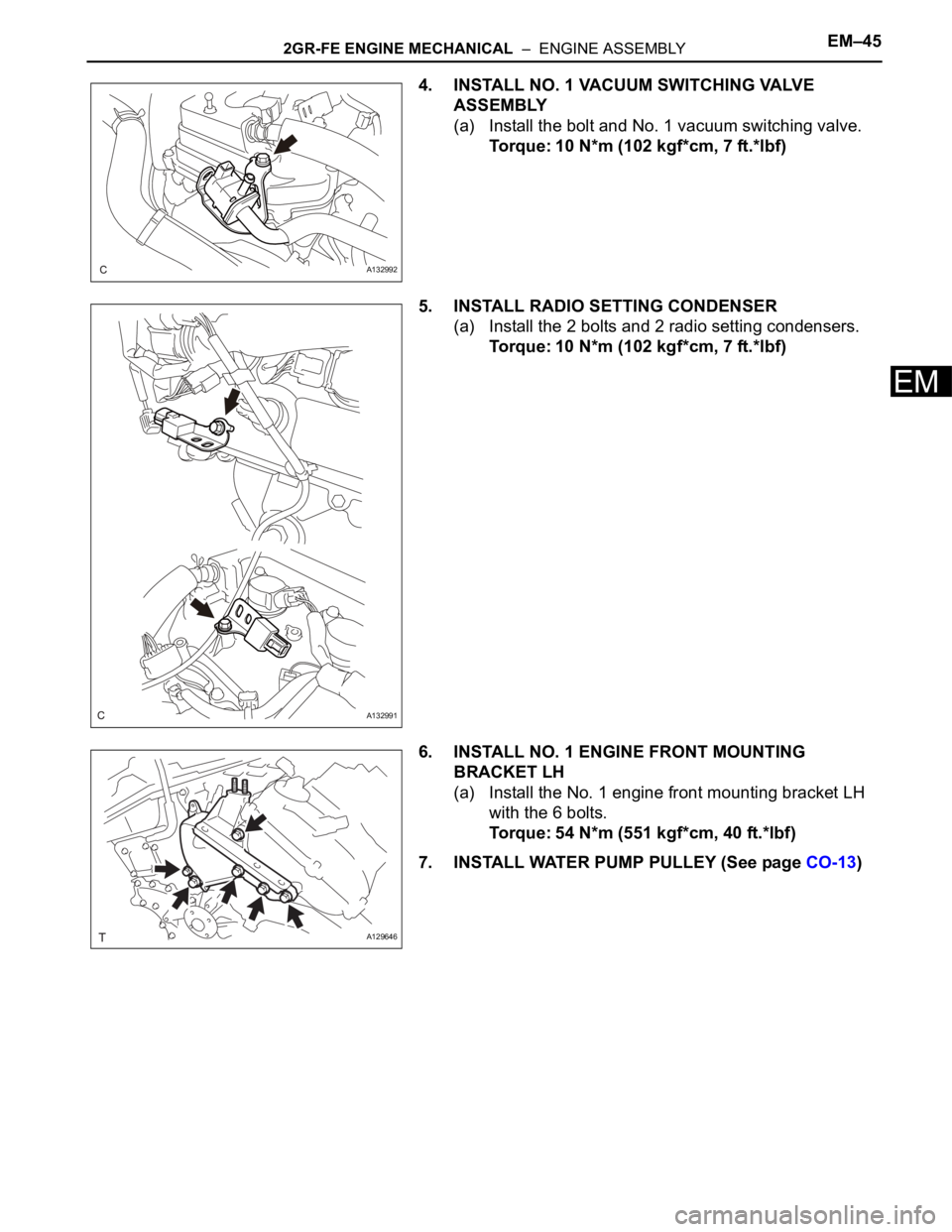
4. INSTALL NO. 1 VACUUM SWITCHING VALVE
ASSEMBLY
(a) Install the bolt and No. 1 vacuum switching valve.
Torque: 10 N*m (102 kgf*cm, 7 ft.*lbf)
5. INSTALL RADIO SETTING CONDENSER
(a) Install the 2 bolts and 2 radio setting condensers.
Torque: 10 N*m (102 kgf*cm, 7 ft.*lbf)
6. INSTALL NO. 1 ENGINE FRONT MOUNTING
BRACKET LH
(a) Install the No. 1 engine front mounting bracket LH
with the 6 bolts.
Torque: 54 N*m (551 kgf*cm, 40 ft.*lbf)
7. INSTALL WATER PUMP PULLEY (See page CO-13)
A132992
A132991
A129646