Page 1236 of 3000

2GR-FE COOLING – WATER PUMPCO–13
CO
INSTALLATION
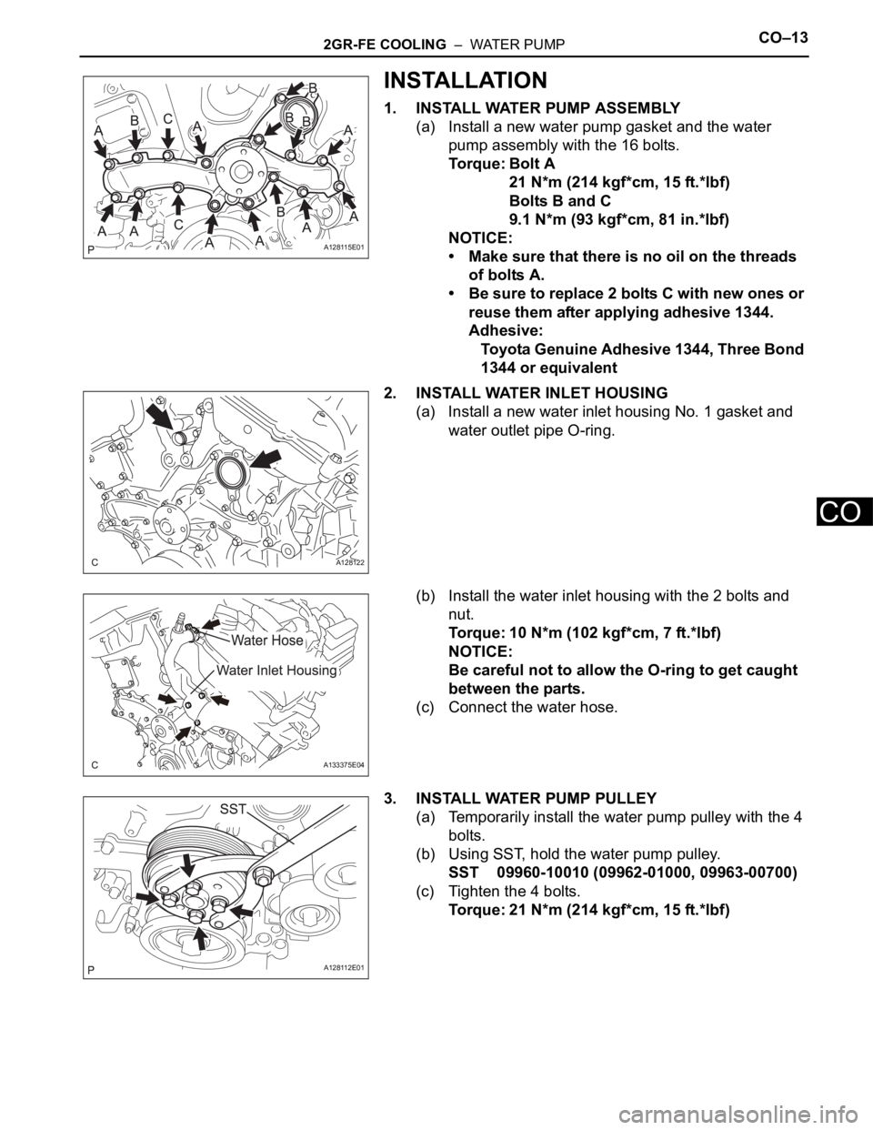
1. INSTALL WATER PUMP ASSEMBLY
(a) Install a new water pump gasket and the water
pump assembly with the 16 bolts.
Torque: Bolt A
21 N*m (214 kgf*cm, 15 ft.*lbf)
Bolts B and C
9.1 N*m (93 kgf*cm, 81 in.*lbf)
NOTICE:
• Make sure that there is no oil on the threads
of bolts A.
• Be sure to replace 2 bolts C with new ones or
reuse them after applying adhesive 1344.
Adhesive:
Toyota Genuine Adhesive 1344, Three Bond
1344 or equivalent
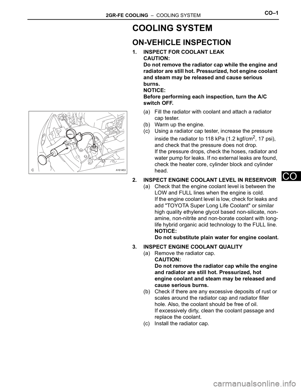
2. INSTALL WATER INLET HOUSING
(a) Install a new water inlet housing No. 1 gasket and
water outlet pipe O-ring.
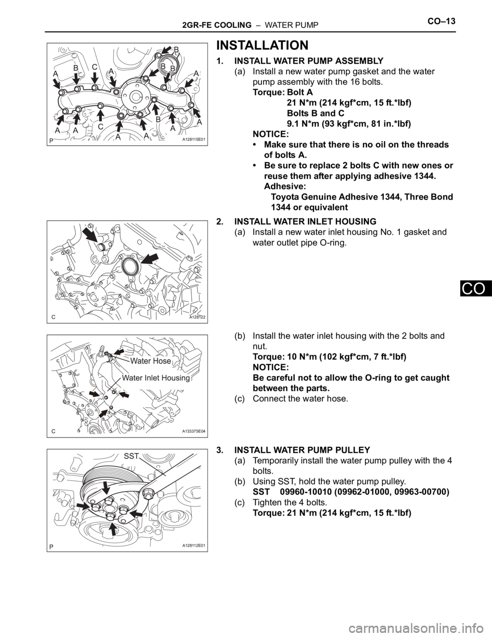
(b) Install the water inlet housing with the 2 bolts and
nut.
Torque: 10 N*m (102 kgf*cm, 7 ft.*lbf)
NOTICE:
Be careful not to allow the O-ring to get caught
between the parts.
(c) Connect the water hose.
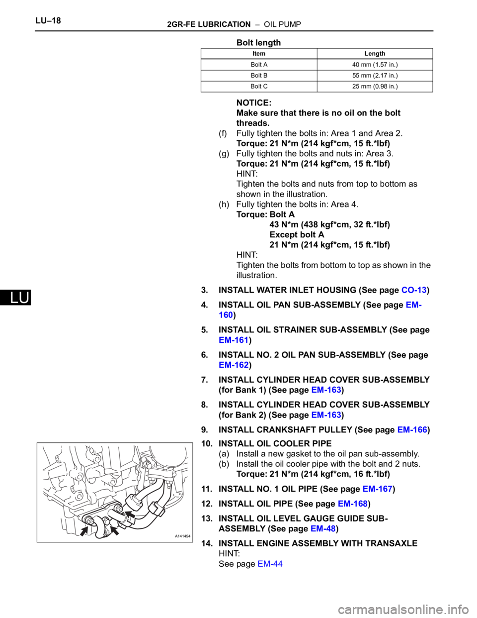
3. INSTALL WATER PUMP PULLEY
(a) Temporarily install the water pump pulley with the 4
bolts.
(b) Using SST, hold the water pump pulley.
SST 09960-10010 (09962-01000, 09963-00700)
(c) Tighten the 4 bolts.
Torque: 21 N*m (214 kgf*cm, 15 ft.*lbf)
A128115E01
A128122
A133375E04
A128112E01
Page 1237 of 3000
CO–142GR-FE COOLING – WATER PUMP
CO
4. INSTALL V-RIBBED BELT TENSIONER ASSEMBLY
(a) Install the V-ribbed belt tensioner assembly with the
5 bolts.
Torque: 43 N*m (438 kgf*cm, 32 ft.*lbf)
5. INSTALL NO. 2 IDLER PULLEY SUB-ASSEMBLY
(a) Install the 2 idler pulley cover plates and idler pulley
sub-assemblies with the 2 bolts.
Torque: 43 N*m (438 kgf*cm, 32 ft.*lbf)
6. INSTALL NO. 1 ENGINE FRONT MOUNTING
BRACKET LH (See page EM-45)
7. INSTALL GENERATOR ASSEMBLY (See page CH-26)
8. INSTALL COMPRESSOR AND MAGNETIC CLUTCH
(See page AC-231)
9. INSTALL ENGINE HANGERS (See page EM-50)
10. REMOVE ENGINE STAND
11. INSTALL ENGINE ASSEMBLY WITH TRANSAXLE
HINT:
See page EM-44
12. ADD ENGINE COOLANT (See page CO-7)
13. INSPECT FOR COOLANT LEAK (See page CO-1)
A161449
A129645E01
Page 1238 of 3000

2GR-FE COOLING – COOLING SYSTEMCO–1
CO
COOLING SYSTEM
ON-VEHICLE INSPECTION
1. INSPECT FOR COOLANT LEAK
CAUTION:
Do not remove the radiator cap while the engine and
radiator are still hot. Pressurized, hot engine coolant
and steam may be released and cause serious
burns.
NOTICE:
Before performing each inspection, turn the A/C
switch OFF.
(a) Fill the radiator with coolant and attach a radiator
cap tester.
(b) Warm up the engine.
(c) Using a radiator cap tester, increase the pressure
inside the radiator to 118 kPa (1.2 kgf/cm
2, 17 psi),
and check that the pressure does not drop.
If the pressure drops, check the hoses, radiator and
water pump for leaks. If no external leaks are found,
check the heater core, cylinder block and cylinder
head.
2. INSPECT ENGINE COOLANT LEVEL IN RESERVOIR
(a) Check that the engine coolant level is between the
LOW and FULL lines when the engine is cold.
If the engine coolant level is low, check for leaks and
add "TOYOTA Super Long Life Coolant" or similar
high quality ethylene glycol based non-silicate, non-
amine, non-nitrite and non-borate coolant with long-
life hybrid organic acid technology to the FULL line.
NOTICE:
Do not substitute plain water for engine coolant.
3. INSPECT ENGINE COOLANT QUALITY
(a) Remove the radiator cap.
CAUTION:
Do not remove the radiator cap while the engine
and radiator are still hot. Pressurized, hot
engine coolant and steam may be released and
cause serious burns.
(b) Check if there are any excessive deposits of rust or
scales around the radiator cap and radiator filler
hole. Also, the coolant should be free of oil.
If excessively dirty, clean the coolant passage and
replace the coolant.
(c) Install the radiator cap.
A161453
Page 1265 of 3000
2GR-FE COOLING – WATER PUMPCO–11
CO
REMOVAL
1. REMOVE ENGINE ASSEMBLY WITH TRANSAXLE
HINT:
See page EM-26
2. SECURE ENGINE (See page EM-37)
3. REMOVE GENERATOR ASSEMBLY (See page CH-17)
4. REMOVE COMPRESSOR AND MAGNETIC CLUTCH
(See page AC-227)
5. REMOVE NO. 1 ENGINE FRONT MOUNTING
BRACKET LH (See page EM-42)
6. REMOVE NO. 2 IDLER PULLEY SUB-ASSEMBLY
(a) Remove the 2 bolts, 2 idler pulley cover plates and 2
idler pulley sub-assemblies.
7. REMOVE V-RIBBED BELT TENSIONER ASSEMBLY
(a) Remove the 5 bolts and V-ribbed belt tensioner
assembly.
A129645E01
A161449
Page 1266 of 3000
CO–122GR-FE COOLING – WATER PUMP
CO
8. REMOVE WATER PUMP PULLEY
(a) Using SST, hold the water pump pulley.
SST 09960-10010 (09962-01000, 09963-00700)
(b) Remove the 4 bolts and water pump pulley.
9. REMOVE WATER INLET HOUSING
(a) Disconnect the water hose.
(b) Remove the 2 bolts, nut and water inlet housing.
(c) Remove the water inlet housing gasket and water
outlet pipe O-ring.
10. REMOVE WATER PUMP ASSEMBLY
(a) Remove the 16 bolts, water pump assembly and
water pump gasket.
INSPECTION
1. INSPECT WATER PUMP ASSEMBLY
(a) Visually check the drain hole and air hole for coolant
leakage.
(b) Turn the pulley, and check that the water pump
bearing moves smoothly and noiselessly.
If the bearing does not move smoothly and
noiselessly, replace the water pump.
A128112E03
A133375E04
A128120
A094889
A096655E06
Page 1267 of 3000

2GR-FE COOLING – WATER PUMPCO–13
CO
INSTALLATION
1. INSTALL WATER PUMP ASSEMBLY
(a) Install a new water pump gasket and the water
pump assembly with the 16 bolts.
Torque: Bolt A
21 N*m (214 kgf*cm, 15 ft.*lbf)
Bolts B and C
9.1 N*m (93 kgf*cm, 81 in.*lbf)
NOTICE:
• Make sure that there is no oil on the threads
of bolts A.
• Be sure to replace 2 bolts C with new ones or
reuse them after applying adhesive 1344.
Adhesive:
Toyota Genuine Adhesive 1344, Three Bond
1344 or equivalent
2. INSTALL WATER INLET HOUSING
(a) Install a new water inlet housing No. 1 gasket and
water outlet pipe O-ring.
(b) Install the water inlet housing with the 2 bolts and
nut.
Torque: 10 N*m (102 kgf*cm, 7 ft.*lbf)
NOTICE:
Be careful not to allow the O-ring to get caught
between the parts.
(c) Connect the water hose.
3. INSTALL WATER PUMP PULLEY
(a) Temporarily install the water pump pulley with the 4
bolts.
(b) Using SST, hold the water pump pulley.
SST 09960-10010 (09962-01000, 09963-00700)
(c) Tighten the 4 bolts.
Torque: 21 N*m (214 kgf*cm, 15 ft.*lbf)
A128115E01
A128122
A133375E04
A128112E01
Page 1268 of 3000
CO–142GR-FE COOLING – WATER PUMP
CO
4. INSTALL V-RIBBED BELT TENSIONER ASSEMBLY
(a) Install the V-ribbed belt tensioner assembly with the
5 bolts.
Torque: 43 N*m (438 kgf*cm, 32 ft.*lbf)
5. INSTALL NO. 2 IDLER PULLEY SUB-ASSEMBLY
(a) Install the 2 idler pulley cover plates and idler pulley
sub-assemblies with the 2 bolts.
Torque: 43 N*m (438 kgf*cm, 32 ft.*lbf)
6. INSTALL NO. 1 ENGINE FRONT MOUNTING
BRACKET LH (See page EM-45)
7. INSTALL GENERATOR ASSEMBLY (See page CH-26)
8. INSTALL COMPRESSOR AND MAGNETIC CLUTCH
(See page AC-231)
9. INSTALL ENGINE HANGERS (See page EM-50)
10. REMOVE ENGINE STAND
11. INSTALL ENGINE ASSEMBLY WITH TRANSAXLE
HINT:
See page EM-44
12. ADD ENGINE COOLANT (See page CO-7)
13. INSPECT FOR COOLANT LEAK (See page CO-1)
A161449
A129645E01
Page 1297 of 3000

LU–182GR-FE LUBRICATION – OIL PUMP
LU
Bolt length
NOTICE:
Make sure that there is no oil on the bolt
threads.
(f) Fully tighten the bolts in: Area 1 and Area 2.
Torque: 21 N*m (214 kgf*cm, 15 ft.*lbf)
(g) Fully tighten the bolts and nuts in: Area 3.
Torque: 21 N*m (214 kgf*cm, 15 ft.*lbf)
HINT:
Tighten the bolts and nuts from top to bottom as
shown in the illustration.
(h) Fully tighten the bolts in: Area 4.
Torque: Bolt A
43 N*m (438 kgf*cm, 32 ft.*lbf)
Except bolt A
21 N*m (214 kgf*cm, 15 ft.*lbf)
HINT:
Tighten the bolts from bottom to top as shown in the
illustration.
3. INSTALL WATER INLET HOUSING (See page CO-13)
4. INSTALL OIL PAN SUB-ASSEMBLY (See page EM-
160)
5. INSTALL OIL STRAINER SUB-ASSEMBLY (See page
EM-161)
6. INSTALL NO. 2 OIL PAN SUB-ASSEMBLY (See page
EM-162)
7. INSTALL CYLINDER HEAD COVER SUB-ASSEMBLY
(for Bank 1) (See page EM-163)
8. INSTALL CYLINDER HEAD COVER SUB-ASSEMBLY
(for Bank 2) (See page EM-163)
9. INSTALL CRANKSHAFT PULLEY (See page EM-166)
10. INSTALL OIL COOLER PIPE
(a) Install a new gasket to the oil pan sub-assembly.
(b) Install the oil cooler pipe with the bolt and 2 nuts.
Torque: 21 N*m (214 kgf*cm, 16 ft.*lbf)
11. INSTALL NO. 1 OIL PIPE (See page EM-167)
12. INSTALL OIL PIPE (See page EM-168)
13. INSTALL OIL LEVEL GAUGE GUIDE SUB-
ASSEMBLY (See page EM-48)
14. INSTALL ENGINE ASSEMBLY WITH TRANSAXLE
HINT:
See page EM-44
Item Length
Bolt A 40 mm (1.57 in.)
Bolt B 55 mm (2.17 in.)
Bolt C 25 mm (0.98 in.)
A141494