Page 31 of 3000
EM–322GR-FE ENGINE MECHANICAL – ENGINE ASSEMBLY
EM
(c) Remove the clip and disconnect the transmission
control cable assembly from the control cable
bracket.
(d) Disconnect the control cable from the control cable
clamp.
38. DISCONNECT RETURN TUBE SUB-ASSEMBLY
(a) Using pliers, grip the claws of the 2 clips and slide
the 2 clips to disconnect the 2 return tube sub-
assemblies.
(b) Drain the power steering fluid.
NOTICE:
Take care not to damage the hose protector.
39. DISCONNECT NO. 1 OIL RESERVOIR TO PUMP
HOSE
(a) Using pliers, grip the claws of the clip and slide the
clip to disconnect the No. 1 oil reservoir to pump
hose from the oil reservoir tank.
40. DISCONNECT ENGINE WIRE
(a) Disconnect the engine wire from the engine room
junction block.
(1) Remove the nut and separate the wire harness.
(2) Using a screwdriver, unlock the engine room
junction block. Pull the engine room junction
block upward.
C089134E01
C090579
A163268
A155029
A155037
Page 33 of 3000

EM–342GR-FE ENGINE MECHANICAL – ENGINE ASSEMBLY
EM
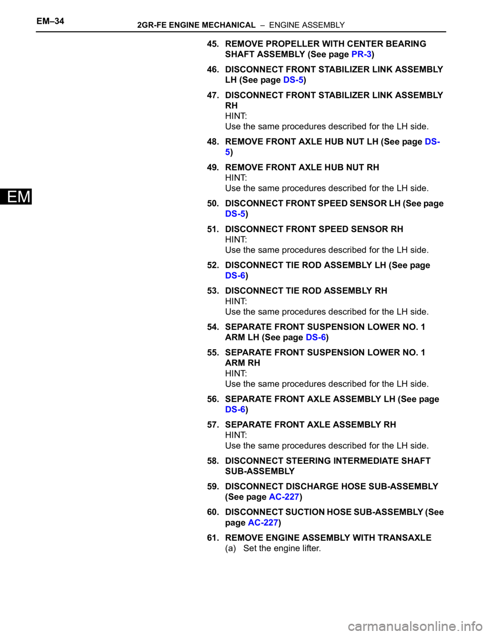
45. REMOVE PROPELLER WITH CENTER BEARING
SHAFT ASSEMBLY (See page PR-3)
46. DISCONNECT FRONT STABILIZER LINK ASSEMBLY
LH (See page DS-5)
47. DISCONNECT FRONT STABILIZER LINK ASSEMBLY
RH
HINT:
Use the same procedures described for the LH side.
48. REMOVE FRONT AXLE HUB NUT LH (See page DS-
5)
49. REMOVE FRONT AXLE HUB NUT RH
HINT:
Use the same procedures described for the LH side.
50. DISCONNECT FRONT SPEED SENSOR LH (See page
DS-5)
51. DISCONNECT FRONT SPEED SENSOR RH
HINT:
Use the same procedures described for the LH side.
52. DISCONNECT TIE ROD ASSEMBLY LH (See page
DS-6)
53. DISCONNECT TIE ROD ASSEMBLY RH
HINT:
Use the same procedures described for the LH side.
54. SEPARATE FRONT SUSPENSION LOWER NO. 1
ARM LH (See page DS-6)
55. SEPARATE FRONT SUSPENSION LOWER NO. 1
ARM RH
HINT:
Use the same procedures described for the LH side.
56. SEPARATE FRONT AXLE ASSEMBLY LH (See page
DS-6)
57. SEPARATE FRONT AXLE ASSEMBLY RH
HINT:
Use the same procedures described for the LH side.
58. DISCONNECT STEERING INTERMEDIATE SHAFT
SUB-ASSEMBLY
59. DISCONNECT DISCHARGE HOSE SUB-ASSEMBLY
(See page AC-227)
60. DISCONNECT SUCTION HOSE SUB-ASSEMBLY (See
page AC-227)
61. REMOVE ENGINE ASSEMBLY WITH TRANSAXLE
(a) Set the engine lifter.
Page 34 of 3000
2GR-FE ENGINE MECHANICAL – ENGINE ASSEMBLYEM–35
EM
(b) Remove the 6 bolts, 2 nuts, and frame side rail
plates RH and LH.
(c) Remove the 6 bolts, 2 nuts, and front suspension
member brace rear RH and LH.
(d) Operate the engine lifter, then remove the engine
assembly from the vehicle.
NOTICE:
Make sure that the engine is clear of all wiring
and hoses.
62. REMOVE V-RIBBED BELT (See page EM-6)
63. REMOVE VANE PUMP ASSEMBLY
(a) Disconnect the power steering oil pressure switch
connector.
(b) Remove the 2 nuts.
(c) Loosen the bolt A.
(d) Remove the bolt B.
(e) Remove the bolt A and vane pump assembly.
64. REMOVE FRONT STABILIZER BAR (for 4WD)
HINT:
See page SP-35.
65. REMOVE POWER STEERING LINK
(a) Remove the 2 bolts and power steering link with
vane pump.
A162364
A162363
A155024
A139216E01
Page 58 of 3000

INTRODUCTION – TERMSIN–51
IN
IFI Indirect Fuel Injection Indirect Injection (IDL)
IFS Inertia Fuel-Shutoff -
ISC Idle Speed Control -
KS Knock Sensor Knock Sensor
MAF Mass Airflow Air Flow Meter
MAP Manifold Absolute Pressure Manifold Pressure Intake Vacuum
MC Mixture ControlElectric Bleed Air Control Valve (EBCV)
Mixture Control Valve (MCV)
Electric Air Control Valve (EACV)
MDP Manifold Differential Pressure -
MFI Multiport Fuel Injection Electronic Fuel Injection (EFI)
MIL Malfunction Indicator Light Check Engine Light
MST Manifold Surface Temperature -
MVZ Manifold Vacuum Zone -
NVRAM Non-Volatile Random Access Memory -
O2S Oxygen SensorOxygen Sensor, O
2 Sensor (O2S)
OBD On-Board Diagnostic On-Board Diagnostic System (OBD)
OC Oxidation Catalytic Converter Oxidation Catalytic Convert (OC), CCo
OL Open Loop Open Loop
PAIR Pulsed Secondary Air Injection Air Suction (AS)
PCM Powertrain Control Module -
PNP Park/Neutral Position -
PROM Programmable Read Only Memory -
PSP Power Steering Pressure -
PTOX Periodic Trap OxidizerDiesel Particulate Filter (DPF)
Diesel Particulate Trap (DPT)
RAM Random Access Memory Random Access Memory (RAM)
RM Relay Module -
ROM Read Only Memory Read Only Memory (ROM)
RPM Engine Speed Engine Speed
SC Supercharger Supercharger
SCB Supercharger Bypass E-ABV
SFI Sequential Multiport Fuel Injection Electronic Fuel Injection (EFI), Sequential Injection
SPL Smoke Puff Limiter -
SRI Service Reminder Indicator -
SRT System Readiness Test -
ST Scan Tool -
TB Throttle Body Throttle Body
TBI Throttle Body Fuel InjectionSingle Point Injection
Central Fuel Injection (Ci)
TC Turbocharger Turbocharger
TCC Torque Converter Clutch Torque Converter
TCM Transmission Control Module Transmission ECU, ECT ECU
TP Throttle Position Throttle Position
TR Transmission Range -
TVV Thermal Vacuum ValveBimetallic Vacuum Switching Valve (BVSV)
Thermostatic Vacuum Switching Valve (TVSV)
TWC Three-Way Catalytic ConverterThree-Way Catalytic (TWC)
Manifold Converter
CC
RO
SAE
ABBREVIATIONSSAE TERMSTOYOTA TERMS
( )-ABBREVIATIONS
Page 110 of 3000

DRIVE SHAFT – FRONT DRIVE SHAFTDS–5
DS
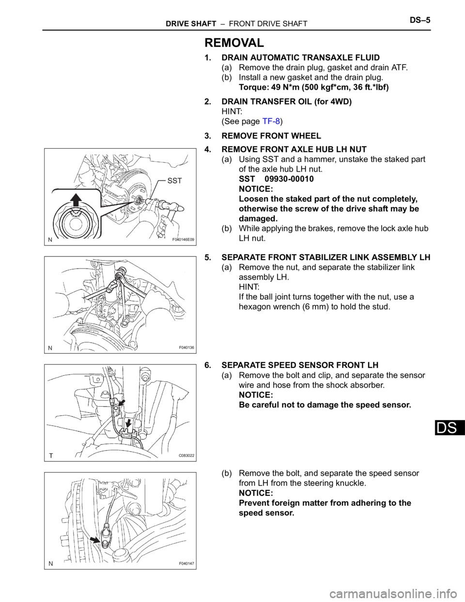
REMOVAL
1. DRAIN AUTOMATIC TRANSAXLE FLUID
(a) Remove the drain plug, gasket and drain ATF.
(b) Install a new gasket and the drain plug.
Torque: 49 N*m (500 kgf*cm, 36 ft.*lbf)
2. DRAIN TRANSFER OIL (for 4WD)
HINT:
(See page TF-8)
3. REMOVE FRONT WHEEL
4. REMOVE FRONT AXLE HUB LH NUT
(a) Using SST and a hammer, unstake the staked part
of the axle hub LH nut.
SST 09930-00010
NOTICE:
Loosen the staked part of the nut completely,
otherwise the screw of the drive shaft may be
damaged.
(b) While applying the brakes, remove the lock axle hub
LH nut.
5. SEPARATE FRONT STABILIZER LINK ASSEMBLY LH
(a) Remove the nut, and separate the stabilizer link
assembly LH.
HINT:
If the ball joint turns together with the nut, use a
hexagon wrench (6 mm) to hold the stud.
6. SEPARATE SPEED SENSOR FRONT LH
(a) Remove the bolt and clip, and separate the sensor
wire and hose from the shock absorber.
NOTICE:
Be careful not to damage the speed sensor.
(b) Remove the bolt, and separate the speed sensor
from LH from the steering knuckle.
NOTICE:
Prevent foreign matter from adhering to the
speed sensor.
F040146E09
F040136
C083022
F040147
Page 111 of 3000

DS–6DRIVE SHAFT – FRONT DRIVE SHAFT
DS
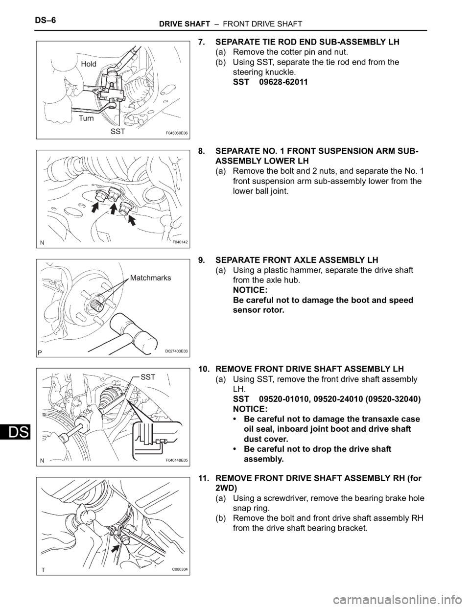
7. SEPARATE TIE ROD END SUB-ASSEMBLY LH
(a) Remove the cotter pin and nut.
(b) Using SST, separate the tie rod end from the
steering knuckle.
SST 09628-62011
8. SEPARATE NO. 1 FRONT SUSPENSION ARM SUB-
ASSEMBLY LOWER LH
(a) Remove the bolt and 2 nuts, and separate the No. 1
front suspension arm sub-assembly lower from the
lower ball joint.
9. SEPARATE FRONT AXLE ASSEMBLY LH
(a) Using a plastic hammer, separate the drive shaft
from the axle hub.
NOTICE:
Be careful not to damage the boot and speed
sensor rotor.
10. REMOVE FRONT DRIVE SHAFT ASSEMBLY LH
(a) Using SST, remove the front drive shaft assembly
LH.
SST 09520-01010, 09520-24010 (09520-32040)
NOTICE:
• Be careful not to damage the transaxle case
oil seal, inboard joint boot and drive shaft
dust cover.
• Be careful not to drop the drive shaft
assembly.
11. REMOVE FRONT DRIVE SHAFT ASSEMBLY RH (for
2WD)
(a) Using a screwdriver, remove the bearing brake hole
snap ring.
(b) Remove the bolt and front drive shaft assembly RH
from the drive shaft bearing bracket.
F045060E06
F040142
D027403E03
F040148E05
C080304
Page 151 of 3000
PP–62PREPARATION – POWER STEERING
PP
RECOMMENDED TOOLS
09040-00011 Hexagon Wrench Set
(09043-20060) Socket Hexagon Wrench 6
09905-00012 Snap Ring No. 1 Expander
Page 152 of 3000
PREPARATION – POWER STEERINGPP–63
PP
EQUIPMENT
Caliper gauge
Vernier calipers
Dial indicator
Feeler gauge
Micrometer
Torque wrench