Page 153 of 3000
PP–64PREPARATION – POWER STEERING
PP
LUBRICANT
Item Capacity Classification
Power steering fluid (Total) 1.0 liters (1.1 US qts, 0.9 Imp. qts) ATF DEXRON II or III or equivalent
Page 154 of 3000
PREPARATION – POWER STEERINGPP–65
PP
SSM
Sealant
Toyota Genuine Adhesive 1344, Three Bond 1344, or equivalent
Page 163 of 3000
AH–6AXLE – FRONT AXLE HUB
AH
REMOVAL
HINT:
Replace the RH side using the same procedures as for the
LH side.
1. REMOVE FRONT WHEEL
2. REMOVE FRONT AXLE HUB LH NUT (See page DS-
5)
3. SEPARATE SPEED SENSOR FRONT LH (See page
DS-5)
4. SEPARATE FRONT DISC BRAKE CALIPER
ASSEMBLY LH
(a) Remove the 2 bolts and separate the front disc
brake caliper assembly LH from the steering
knuckle LH.
NOTICE:
Use a string or other device to keep the brake
caliper from hanging down.
5. REMOVE FRONT DISC
6. SEPARATE TIE ROD END SUB-ASSEMBLY LH (See
page DS-6)
7. SEPARATE FRONT SUSPENSION ARM SUB-
ASSEMBLY LOWER NO.1 LH (See page DS-6)
8. REMOVE FRONT AXLE ASSEMBLY LH
(a) Using a plastic hammer, separate the front drive
shaft assembly LH from the front axle hub sub-
assembly LH.
NOTICE:
Be careful not to damage the boot and ABS
speed sensor rotor.
(b) Remove the 2 bolts, nuts and steering knuckle LH
with the front axle nub sub-assembly LH.
C067088
D027403
C083023
Page 165 of 3000
AH–8AXLE – FRONT AXLE HUB
AH
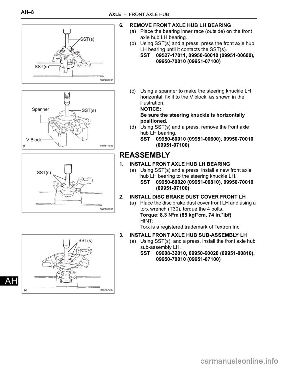
6. REMOVE FRONT AXLE HUB LH BEARING
(a) Place the bearing inner race (outside) on the front
axle hub LH bearing.
(b) Using SST(s) and a press, press the front axle hub
LH bearing until it contacts the SST(s).
SST 09527-17011, 09950-60010 (09951-00600),
09950-70010 (09951-07100)
(c) Using a spanner to make the steering knuckle LH
horizontal, fix it to the V block, as shown in the
illustration.
NOTICE:
Be sure the steering knuckle is horizontally
positioned.
(d) Using SST(s) and a press, remove the front axle
hub LH bearing.
SST 09950-60010 (09951-00600), 09950-70010
(09951-07100)
REASSEMBLY
1. INSTALL FRONT AXLE HUB LH BEARING
(a) Using SST(s) and a press, install a new front axle
hub LH bearing to the steering knuckle LH.
SST 09950-60020 (09951-00810), 09950-70010
(09951-07100)
2. INSTALL DISC BRAKE DUST COVER FRONT LH
(a) Place the disc brake dust cover front LH and using a
torx wrench (T30), torque the 4 bolts.
Torque: 8.3 N*m (85 kgf*cm, 74 in.*lbf)
HINT:
Torx is a registered trademark of Textron Inc.
3. INSTALL FRONT AXLE HUB SUB-ASSEMBLY LH
(a) Using SST(s), and a press, install the front axle hub
sub-assembly LH.
SST 09608-32010, 09950-60020 (09951-00810),
09950-70010 (09951-07100)
F040230E05
F011547E03
F040231E07
F040157E02
Page 166 of 3000
AXLE – FRONT AXLE HUBAH–9
AH
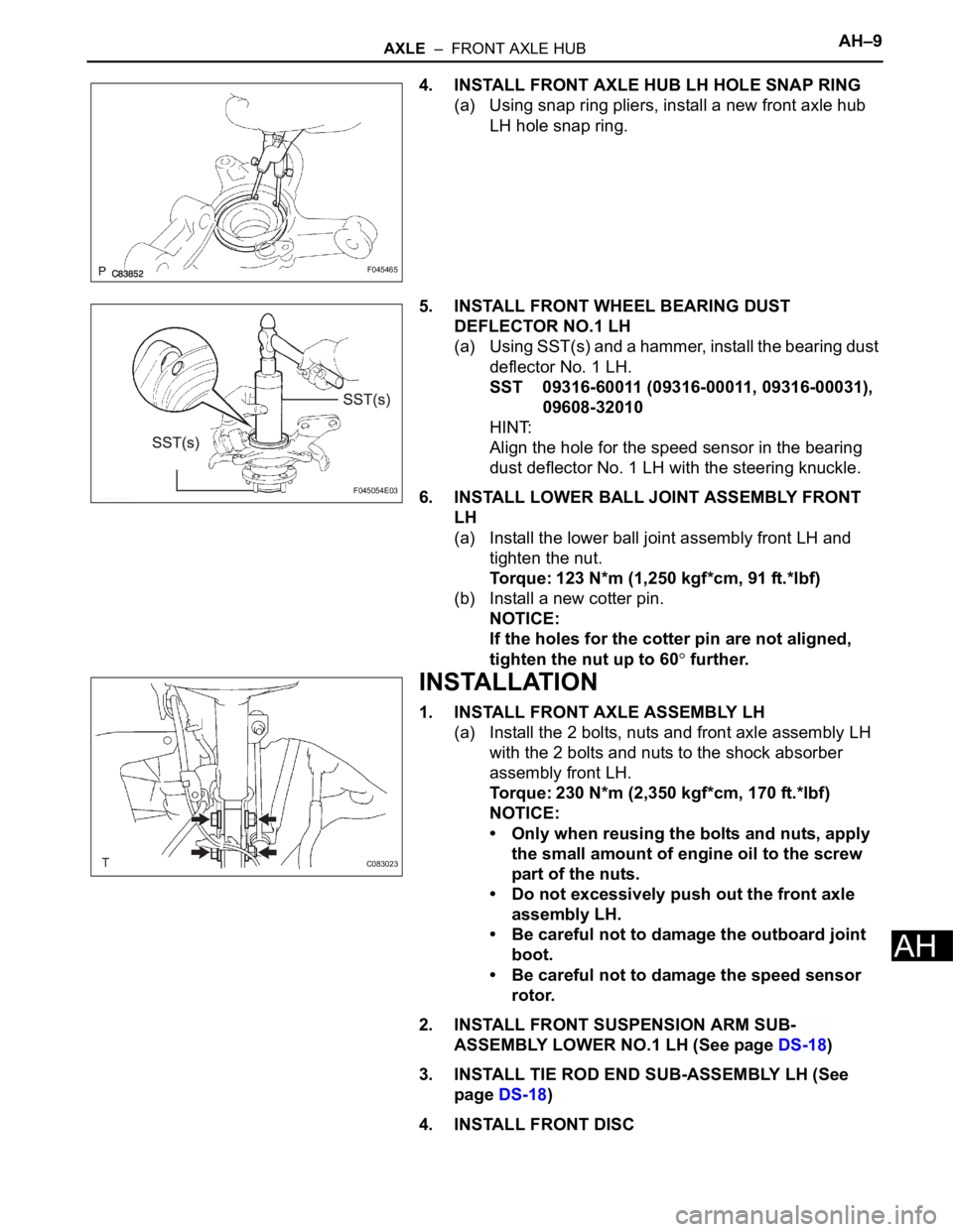
4. INSTALL FRONT AXLE HUB LH HOLE SNAP RING
(a) Using snap ring pliers, install a new front axle hub
LH hole snap ring.
5. INSTALL FRONT WHEEL BEARING DUST
DEFLECTOR NO.1 LH
(a) Using SST(s) and a hammer, install the bearing dust
deflector No. 1 LH.
SST 09316-60011 (09316-00011, 09316-00031),
09608-32010
HINT:
Align the hole for the speed sensor in the bearing
dust deflector No. 1 LH with the steering knuckle.
6. INSTALL LOWER BALL JOINT ASSEMBLY FRONT
LH
(a) Install the lower ball joint assembly front LH and
tighten the nut.
Torque: 123 N*m (1,250 kgf*cm, 91 ft.*lbf)
(b) Install a new cotter pin.
NOTICE:
If the holes for the cotter pin are not aligned,
tighten the nut up to 60
further.
INSTALLATION
1. INSTALL FRONT AXLE ASSEMBLY LH
(a) Install the 2 bolts, nuts and front axle assembly LH
with the 2 bolts and nuts to the shock absorber
assembly front LH.
Torque: 230 N*m (2,350 kgf*cm, 170 ft.*lbf)
NOTICE:
• Only when reusing the bolts and nuts, apply
the small amount of engine oil to the screw
part of the nuts.
• Do not excessively push out the front axle
assembly LH.
• Be careful not to damage the outboard joint
boot.
• Be careful not to damage the speed sensor
rotor.
2. INSTALL FRONT SUSPENSION ARM SUB-
ASSEMBLY LOWER NO.1 LH (See page DS-18)
3. INSTALL TIE ROD END SUB-ASSEMBLY LH (See
page DS-18)
4. INSTALL FRONT DISC
F045465
F045054E03
C083023
Page 167 of 3000
AH–10AXLE – FRONT AXLE HUB
AH
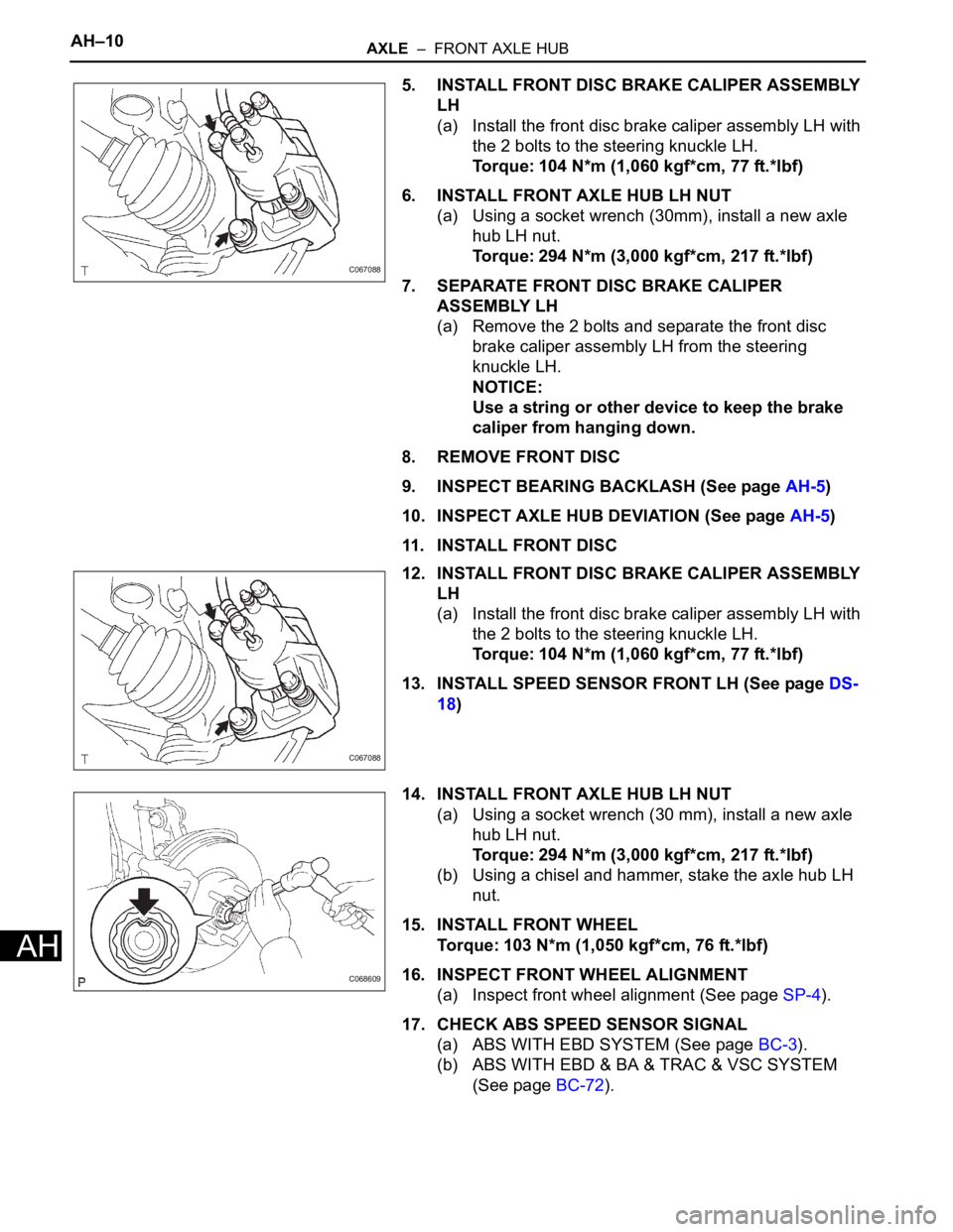
5. INSTALL FRONT DISC BRAKE CALIPER ASSEMBLY
LH
(a) Install the front disc brake caliper assembly LH with
the 2 bolts to the steering knuckle LH.
Torque: 104 N*m (1,060 kgf*cm, 77 ft.*lbf)
6. INSTALL FRONT AXLE HUB LH NUT
(a) Using a socket wrench (30mm), install a new axle
hub LH nut.
Torque: 294 N*m (3,000 kgf*cm, 217 ft.*lbf)
7. SEPARATE FRONT DISC BRAKE CALIPER
ASSEMBLY LH
(a) Remove the 2 bolts and separate the front disc
brake caliper assembly LH from the steering
knuckle LH.
NOTICE:
Use a string or other device to keep the brake
caliper from hanging down.
8. REMOVE FRONT DISC
9. INSPECT BEARING BACKLASH (See page AH-5)
10. INSPECT AXLE HUB DEVIATION (See page AH-5)
11. INSTALL FRONT DISC
12. INSTALL FRONT DISC BRAKE CALIPER ASSEMBLY
LH
(a) Install the front disc brake caliper assembly LH with
the 2 bolts to the steering knuckle LH.
Torque: 104 N*m (1,060 kgf*cm, 77 ft.*lbf)
13. INSTALL SPEED SENSOR FRONT LH (See page DS-
18)
14. INSTALL FRONT AXLE HUB LH NUT
(a) Using a socket wrench (30 mm), install a new axle
hub LH nut.
Torque: 294 N*m (3,000 kgf*cm, 217 ft.*lbf)
(b) Using a chisel and hammer, stake the axle hub LH
nut.
15. INSTALL FRONT WHEEL
Torque: 103 N*m (1,050 kgf*cm, 76 ft.*lbf)
16. INSPECT FRONT WHEEL ALIGNMENT
(a) Inspect front wheel alignment (See page SP-4).
17. CHECK ABS SPEED SENSOR SIGNAL
(a) ABS WITH EBD SYSTEM (See page BC-3).
(b) ABS WITH EBD & BA & TRAC & VSC SYSTEM
(See page BC-72).
C067088
C067088
C068609
Page 168 of 3000
SUSPENSION – SUSPENSION SYSTEMSP–3
SP
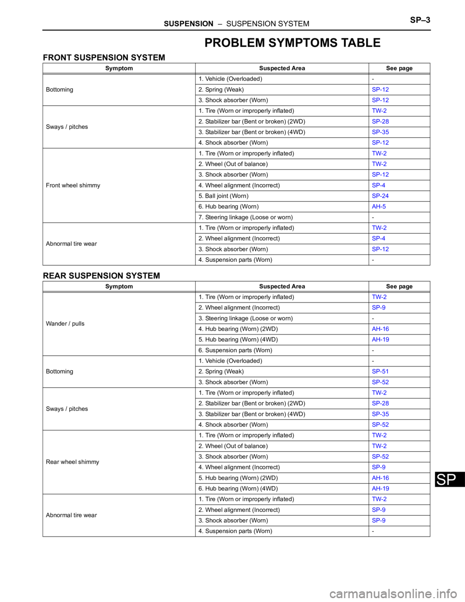
PROBLEM SYMPTOMS TABLE
FRONT SUSPENSION SYSTEM
REAR SUSPENSION SYSTEM
Symptom Suspected Area See page
Bottoming1. Vehicle (Overloaded) -
2. Spring (Weak)SP-12
3. Shock absorber (Worn)SP-12
Sways / pitches1. Tire (Worn or improperly inflated)TW-2
2. Stabilizer bar (Bent or broken) (2WD)SP-28
3. Stabilizer bar (Bent or broken) (4WD)SP-35
4. Shock absorber (Worn)SP-12
Front wheel shimmy1. Tire (Worn or improperly inflated)TW-2
2. Wheel (Out of balance)TW-2
3. Shock absorber (Worn)SP-12
4. Wheel alignment (Incorrect)SP-4
5. Ball joint (Worn)SP-24
6. Hub bearing (Worn)AH-5
7. Steering linkage (Loose or worn) -
Abnormal tire wear1. Tire (Worn or improperly inflated)TW-2
2. Wheel alignment (Incorrect)SP-4
3. Shock absorber (Worn)SP-12
4. Suspension parts (Worn) -
Symptom Suspected Area See page
Wander / pulls1. Tire (Worn or improperly inflated)TW-2
2. Wheel alignment (Incorrect)SP-9
3. Steering linkage (Loose or worn) -
4. Hub bearing (Worn) (2WD)AH-16
5. Hub bearing (Worn) (4WD)AH-19
6. Suspension parts (Worn) -
Bottoming1. Vehicle (Overloaded) -
2. Spring (Weak)SP-51
3. Shock absorber (Worn)SP-52
Sways / pitches1. Tire (Worn or improperly inflated)TW-2
2. Stabilizer bar (Bent or broken) (2WD)SP-28
3. Stabilizer bar (Bent or broken) (4WD)SP-35
4. Shock absorber (Worn)SP-52
Rear wheel shimmy1. Tire (Worn or improperly inflated)TW-2
2. Wheel (Out of balance)TW-2
3. Shock absorber (Worn)SP-52
4. Wheel alignment (Incorrect)SP-9
5. Hub bearing (Worn) (2WD)AH-16
6. Hub bearing (Worn) (4WD)AH-19
Abnormal tire wear1. Tire (Worn or improperly inflated)TW-2
2. Wheel alignment (Incorrect)SP-9
3. Shock absorber (Worn)SP-9
4. Suspension parts (Worn) -
Page 180 of 3000
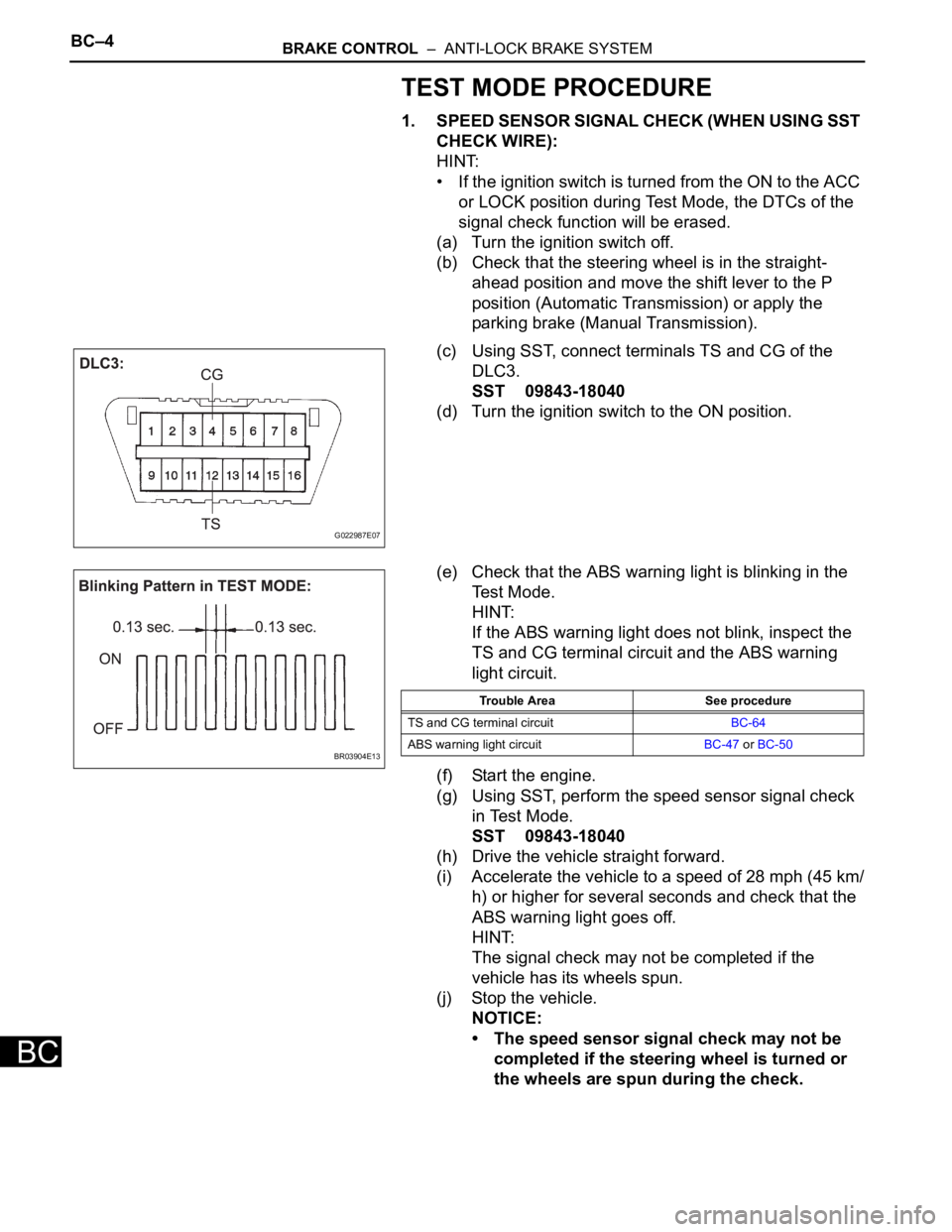
BC–4BRAKE CONTROL – ANTI-LOCK BRAKE SYSTEM
BC
TEST MODE PROCEDURE
1. SPEED SENSOR SIGNAL CHECK (WHEN USING SST
CHECK WIRE):
HINT:
• If the ignition switch is turned from the ON to the ACC
or LOCK position during Test Mode, the DTCs of the
signal check function will be erased.
(a) Turn the ignition switch off.
(b) Check that the steering wheel is in the straight-
ahead position and move the shift lever to the P
position (Automatic Transmission) or apply the
parking brake (Manual Transmission).
(c) Using SST, connect terminals TS and CG of the
DLC3.
SST 09843-18040
(d) Turn the ignition switch to the ON position.
(e) Check that the ABS warning light is blinking in the
Test Mode.
HINT:
If the ABS warning light does not blink, inspect the
TS and CG terminal circuit and the ABS warning
light circuit.
(f) Start the engine.
(g) Using SST, perform the speed sensor signal check
in Test Mode.
SST 09843-18040
(h) Drive the vehicle straight forward.
(i) Accelerate the vehicle to a speed of 28 mph (45 km/
h) or higher for several seconds and check that the
ABS warning light goes off.
HINT:
The signal check may not be completed if the
vehicle has its wheels spun.
(j) Stop the vehicle.
NOTICE:
• The speed sensor signal check may not be
completed if the steering wheel is turned or
the wheels are spun during the check.
G022987E07
BR03904E13
Trouble Area See procedure
TS and CG terminal circuitBC-64
ABS warning light circuitBC-47 or BC-50