Page 195 of 3000

POWER STEERING – VANE PUMPPS–13
PS
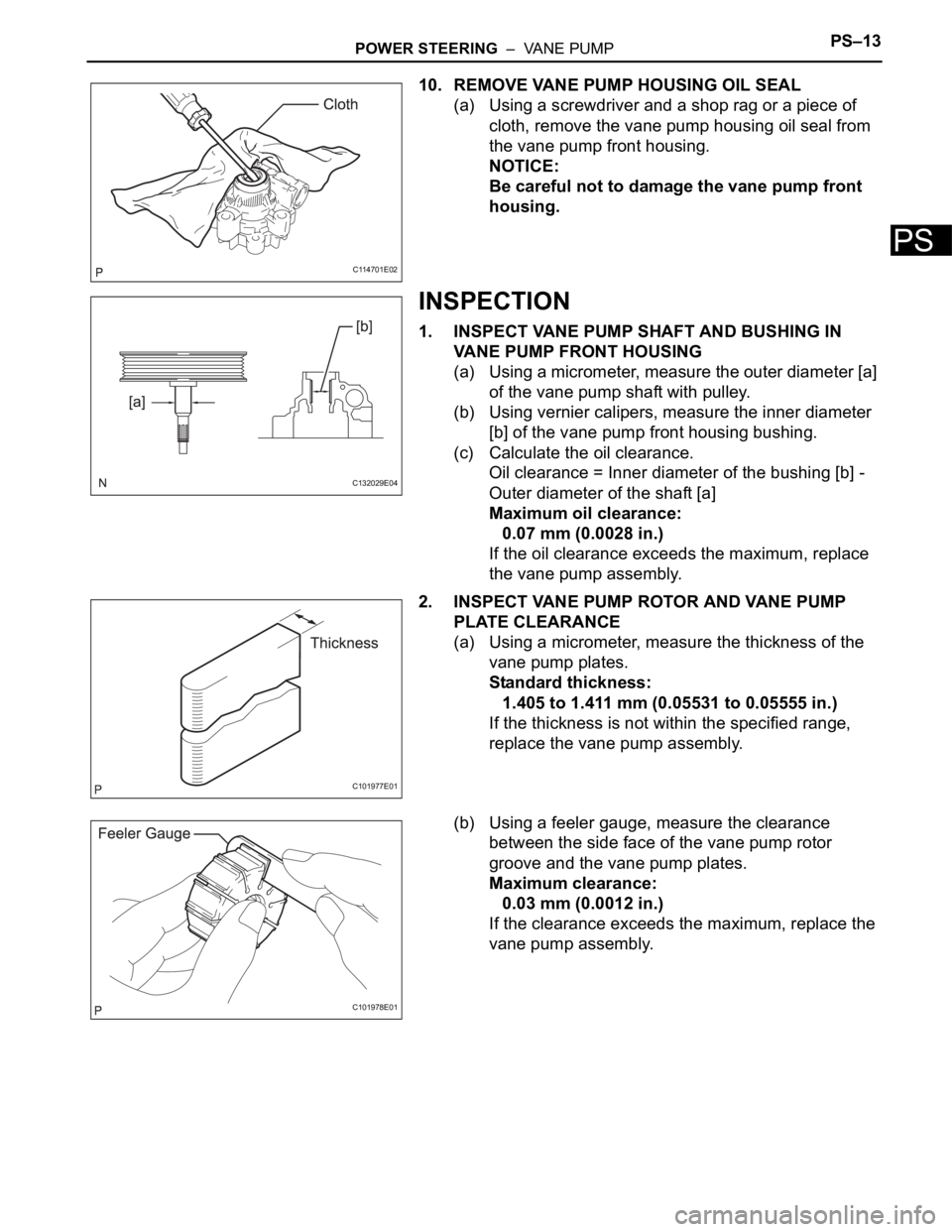
10. REMOVE VANE PUMP HOUSING OIL SEAL
(a) Using a screwdriver and a shop rag or a piece of
cloth, remove the vane pump housing oil seal from
the vane pump front housing.
NOTICE:
Be careful not to damage the vane pump front
housing.
INSPECTION
1. INSPECT VANE PUMP SHAFT AND BUSHING IN
VANE PUMP FRONT HOUSING
(a) Using a micrometer, measure the outer diameter [a]
of the vane pump shaft with pulley.
(b) Using vernier calipers, measure the inner diameter
[b] of the vane pump front housing bushing.
(c) Calculate the oil clearance.
Oil clearance = Inner diameter of the bushing [b] -
Outer diameter of the shaft [a]
Maximum oil clearance:
0.07 mm (0.0028 in.)
If the oil clearance exceeds the maximum, replace
the vane pump assembly.
2. INSPECT VANE PUMP ROTOR AND VANE PUMP
PLATE CLEARANCE
(a) Using a micrometer, measure the thickness of the
vane pump plates.
Standard thickness:
1.405 to 1.411 mm (0.05531 to 0.05555 in.)
If the thickness is not within the specified range,
replace the vane pump assembly.
(b) Using a feeler gauge, measure the clearance
between the side face of the vane pump rotor
groove and the vane pump plates.
Maximum clearance:
0.03 mm (0.0012 in.)
If the clearance exceeds the maximum, replace the
vane pump assembly.
C114701E02
C132029E04
C101977E01
C101978E01
Page 196 of 3000

PS–14POWER STEERING – VANE PUMP
PS
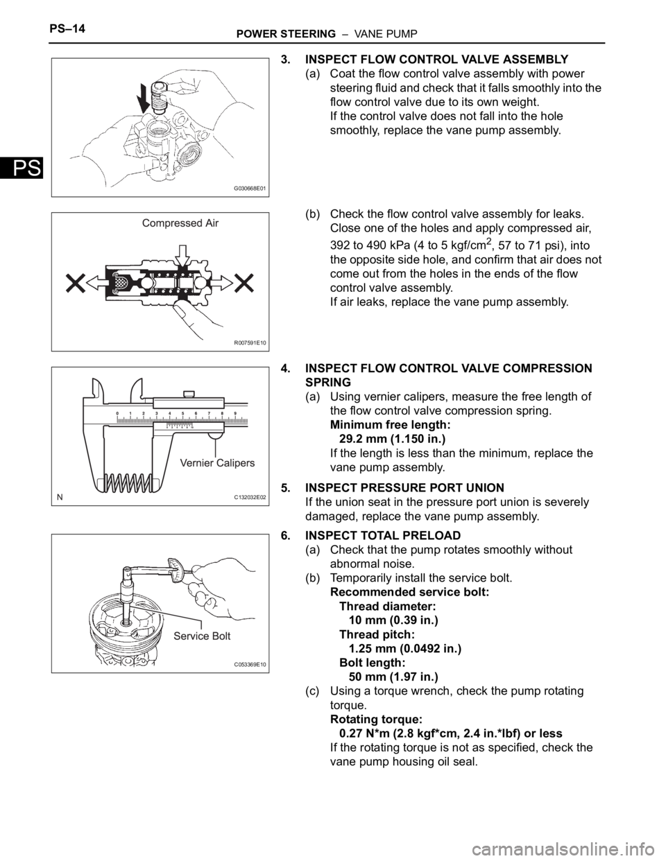
3. INSPECT FLOW CONTROL VALVE ASSEMBLY
(a) Coat the flow control valve assembly with power
steering fluid and check that it falls smoothly into the
flow control valve due to its own weight.
If the control valve does not fall into the hole
smoothly, replace the vane pump assembly.
(b) Check the flow control valve assembly for leaks.
Close one of the holes and apply compressed air,
392 to 490 kPa (4 to 5 kgf/cm
2, 57 to 71 psi), into
the opposite side hole, and confirm that air does not
come out from the holes in the ends of the flow
control valve assembly.
If air leaks, replace the vane pump assembly.
4. INSPECT FLOW CONTROL VALVE COMPRESSION
SPRING
(a) Using vernier calipers, measure the free length of
the flow control valve compression spring.
Minimum free length:
29.2 mm (1.150 in.)
If the length is less than the minimum, replace the
vane pump assembly.
5. INSPECT PRESSURE PORT UNION
If the union seat in the pressure port union is severely
damaged, replace the vane pump assembly.
6. INSPECT TOTAL PRELOAD
(a) Check that the pump rotates smoothly without
abnormal noise.
(b) Temporarily install the service bolt.
Recommended service bolt:
Thread diameter:
10 mm (0.39 in.)
Thread pitch:
1.25 mm (0.0492 in.)
Bolt length:
50 mm (1.97 in.)
(c) Using a torque wrench, check the pump rotating
torque.
Rotating torque:
0.27 N*m (2.8 kgf*cm, 2.4 in.*lbf) or less
If the rotating torque is not as specified, check the
vane pump housing oil seal.
G030668E01
R007591E10
C132032E02
C053369E10
Page 197 of 3000

SS–10SERVICE SPECIFICATIONS – 2GR-FE ENGINE MECHANICAL
SS
TORQUE SPECIFICATIONS
Part Tightened N*m kgf*cm ft.*lbf
Ignition coil assembly x Cylinder head cover sub-assembly 10 102 7
No. 1 engine hanger x Cylinder head sub-assembly RH 33 337 24
No. 2 engine hanger x Cylinder head sub-assembly LH 33 337 24
Engine mounting bracket RH x Cylinder block sub-assembly 54 551 40
No. 1 oil level gauge guide x Cylinder head sub-assembly 21 214 15
No. 2 oil level gauge guide x Cylinder block sub-assembly 21 214 15
No. 2 idler pulley sub-assembly x Timing chain cover sub-assembly 43 438 32
V-ribbed belt tensioner assembly x Cylinder block sub-assembly 43 438 32
Intake manifold x Cylinder head sub-assembly 21 214 15
Exhaust manifold sub-assembly RH x Cylinder head sub-assembly
RH21 214 15
Exhaust manifold sub-assembly LH x Cylinder head sub-assembly LH 21 214 15
Drive plate & ring gear sub-assembly x Crankshaft 83 850 61
Air cleaner case sub-assembly x Body 5.0 51 44 in.*lbf
Air cleaner case sub-assembly x Air cleaner bracket 5.0 51 44 in.*lbf
Engine coolant temperature x water by-pass joint RR 20 200 14
Engine assembly with Transaxle x Body A 85 867 63
B 32 329 24
No. 2 manifold stay x Exhaust manifold sub-assembly LH 34 347 25
No. 2 manifold stay x Cylinder block sub-assembly 34 347 25
No. 1 air cleaner inlet x Body 5.0 51 44 in.*lbf
No. 2 air cleaner inlet x Body 5.0 51 44 in.*lbf
Battery clamp x Body Bolt 5.5 56 49 in.*lbf
Nut 5.5 56 49 in.*lbf
Throttle body bracket x Intake air surge tank assembly 21 214 15
Throttle body bracket x Cylinder head cover sub-assembly RH 21 21415
No. 1 surge tank stay x Intake air surge tank assembly 21 214 15
No. 1 surge tank stay x Cylinder head cover sub-assembly RH 21 21415
No. 1 cowl top to cowl brace inner x Body 7.5 76 66 in.*lbf
No. 1 cowl top to cowl brace inner x Front outer cowl top panel sub-
assembly7.5 76 66 in.*lbf
Front outer cowl top panel sub-assembly x Body 7.5 76 66 in.*lbf
Fuel pump resistor x Front outer cowl top panel sub-assembly 7.576 66 in.*lbf
Radio setting condenser x Cylinder head cover sub-assembly RH 10102 7
Radio setting condense x Cylinder head cover sub-assembly LH 10 102 7
Intake air resonator sub-assembly x Body 5.0 51 44 in.*lbf
Air cleaner bracket x Body 7.8 80 69 in.*lbf
No. 1 vacuum switching valve assembly x Cylinder head cover sub-
assembly10 102 7
Engine mounting bracket RR x Cylinder block sub-assembly 64 650 47
Steering intermediate shaft x Steering gear 35 360 26
Stabilizer link x Shock absorber 74 755 55
Tie rod assembly x Steering gear 49 500 36
Front speed sensor x Front axle 8.0 85 71 in.*lbf
Front axle hub nut x Front drive shaft 294 2998 217
Cooler compressor assembly x V-ribbed belt tensioner 25 250 18
Cooler compressor assembly x Discharge hose sub-assembly 5.4 55 48 in.*lbf
Cooler compressor assembly x Suction hose sub-assembly 5.4 55 48 in.*lbf
Page 249 of 3000
LI–104LIGHTING – HEADLIGHT DIMMER SWITCH
LI
INSTALLATION
1. INSTALL HEADLIGHT DIMMER SWITCH ASSEMBLY
2. INSTALL STEERING COLUMN UPPER COVER
3. INSTALL STEERING COLUMN LOWER COVER
Page 261 of 3000
AV–200AUDIO / VISUAL – STEERING PAD SWITCH
AV
INSPECTION
1. INSPECT STEERING PAD SWITCH LH (w/o
Navigation System)
(a) Measure the resistance according to the values in
the table below.
Standard resistance
If the result is not as specified, replace the steering
pad switch LH.
Tester connection Condition Specified condition
AU1 - EAU No switch is pushed Approx. 100 k
AU1 - EAU SEEK+ switch: push Approx. 0
AU1 - EAU SEEK- switch: push Approx. 0.3 k
AU1 - EAU VOL+ switch: push Approx. 1 k
AU1 - EAU VOL- switch: push Approx. 3.2 k
AU2 - EAU No switch is pushed Approx. 100 k
AU2 - EAU MODE switch: push Approx. 0
I039169E02
Page 262 of 3000
AUDIO / VISUAL – STEERING PAD SWITCHAV – 2 0 1
AV
2. INSPECT STEERING PAD SWITCH RH (w/ Navigation
System)
(a) Measure the resistance according to the value(s) in
the table below.
Standard resistance
If the result is not as specified, replace the steering
pad switch RH.
Tester connection Condition Specified condition
AU2 (B-4) - EAU (B-2)
No switch is pushed 10 k
or higher AU2 (B-5) - EAU (B-3)
AU2 (B-5) - EAU (B-2)
AU2 (B-4) - EAU (B-3)
AU2 (B-4) - EAU (B-2)
VOICE switch: push Approx. 3.2 k
AU2 (B-5) - EAU (B-3)
AU2 (B-5) - EAU (B-2)
AU2 (B-4) - EAU (B-3)
AU2 (B-4) - EAU (B-2)
ON HOOK switch: push Approx. 0.3 k
AU2 (B-5) - EAU (B-3)
AU2 (B-5) - EAU (B-2)
AU2 (B-4) - EAU (B-3)
AU2 (B-4) - EAU (B-2)
OFF HOOK switch: push Approx. 1 k
AU2 (B-5) - EAU (B-3)
AU2 (B-5) - EAU (B-2)
AU2 (B-4) - EAU (B-3)
E120114E01
Page 263 of 3000
AV–202AUDIO / VISUAL – STEERING PAD SWITCH
AV
3. INSPECT STEERING PAD SWITCH CABLE (w/
Navigation System)
(a) Measure the resistance according to the value(s) in
the table below.
Standard resistance
If the result is not as specified, replace the steering
pad switch cable.
Tester connection Condition Specified condition
B-1 - C-1 Always Below 1
B-2 - C-2 Always Below 1
B-3 - C-3 Always Below 1
B-4 - C-4 Always Below 1
B-5 - C-5 Always Below 1
B-6 - C-6 Always Below 1
B-7 - C-7 Always Below 1
B-8 - C-8 Always Below 1
B-1 - Body ground Always 10 k or higher
B-2 - Body ground Always 10 k
or higher
B-3 - Body ground Always 10 k
or higher
B-4 - Body ground Always 10 k
or higher
B-5 - Body ground Always 10 k
or higher
B-6 - Body ground Always 10 k
or higher
B-7 - Body ground Always 10 k
or higher
B-8 - Body ground Always 10 k
or higher
E120113E02
Page 289 of 3000
INSTRUMENT PANEL – INSTRUMENT PANEL SAFETY PADIP–5
IP
REMOVAL
1. BOLT, SCREW AND NUT TABLE
(a) The bolts, the screws and the nuts, which are
necessary for installation and removal of the
instrument panel are shown in the illustration below
with alphabets.
2. DISCONNECT BATTERY NEGATIVE TERMINAL (See
page RS-423)
3. REMOVE STEERING WHEEL COVER LOWER NO.2
4. REMOVE STEERING WHEEL COVER LOWER NO.3
5. REMOVE HORN BUTTON ASSEMBLY (See page RS-
424)
6. REMOVE STEERING WHEEL ASSEMBLY (See page
SR-6)
7. REMOVE STEERING COLUMN COVER (See page
RS-434)
8. REMOVE HEADLIGHT DIMMER SWITCH ASSEMBLY
(See page LI-102)
9. REMOVE WINDSHIELD WIPER SWITCH ASSEMBLY
(See page WW-17)
B066709E01